 Hongpeng Liu1
 Wei Zhang
94% of researchers rate our articles as excellent or good
Learn more about the work of our research integrity team to safeguard the quality of each article we publish.
Find out more
ORIGINAL RESEARCH article
Front. Electron., 16 August 2023
Sec. Power Electronics
Volume 4 - 2023 | https://doi.org/10.3389/felec.2023.1226006
The charging modules of Electric vehicles (EVs) always run in a complex and variable state. As the weakness in the reliable operation of charging modules, the accurate lifetime prediction of aluminum electrolytic capacitors (Al-caps) is important for the later maintenance and reliability design. The hotspot temperature calculation method and lifetime model limit the accuracy of aluminum electrolytic capacitors lifetime prediction methods, which cannot meet the increasing requirements for reliability. In order to solve the problems above, this paper has proposed a hotspot temperature calculation method based on the ripple current with frequency characteristics and the cooling conditions on the heat generation and thermal conductivity of the capacitors. Furthermore, the lifetime model under reference voltage has been constructed with 3D surface fitting toolbox, which describes the trends of capacitor lifetime with ambient temperature and hotspot temperature under the constant voltage condition. Considering the variation of voltage, the multiple lifetime model of capacitor is established with a voltage correction coefficient. With the proposed method, it can be realized about the real-time lifetime prediction of capacitors under multiple operating profiles such as ripple current, thermal dissipation conditions, ambient temperature and operating voltage. Finally, the effectiveness of the proposed method is verified with the annual profiles of a 30 kW EV charging module.
As the fundamental supporting facilities for EVs, the safety and reliability of charging are the effective ways to promote and stimulate the market potential of EVs industry (Blaabjerg et al., 2021; Al-Hanahi et al., 2021). Al-caps is an essential component of charging equipment, which is always used on the DC side of the converter to balance transient power and improve power quality. However, Al-caps is also one of the components with the highest failure rate in charging modules (Wen et al., 2012). Thus, the lifetime prediction of dc-link capacitors in EV charging equipment plays a vital role in reliability assessment (Wang et al., 2021; Zeng et al., 2020), which is essential for the operation and maintenance of EV charging equipment.
Real-time acquisition of hotspot temperature information in the capacitor plays a critical role in reliability analysis. Due to the problem of capacitor packaging, the hotspot temperature of Al-caps is difficult to measure directly. Therefore, the power loss and hotspot temperature of capacitors are usually estimated by monitoring the magnitude of the ripple current and Equivalent series resistance (ESR). In (Lledó-Ponsati et al., 2021), on a basis of the internal geometry of large capacitors, a thermal model is proposed to improve the estimation accuracy of the capacitor hotspot temperature. In (An and Lu, 2016), the power loss of dc-link capacitors in cascaded two-stage converters have been calculated by the Root-Mean-Square (RMS) value of ripple current with different duty cycle combinations. However, the value of ESR is mainly determined by the electrolyte resistance and dielectric loss, varying with temperature and ripple frequency. In all the papers above, it has been employed about the RMS value of capacitor current for power loss and hotspot temperature calculation which leads to the error of hotspot temperature calculation because of neglecting the frequency characteristics of ESR. In (Zhao et al., 2021; Shen et al., 2019), the effects of temperature characteristics of ESR, transient processes and thermal coupling between components have been investigated, which can effectively improve the accuracy of hotspot temperature calculation. However, all these researches neglect the influence of thermal dissipation conditions on the ESR and thermal resistance, which affect the accuracy of temperature calculation. Therefore, in order to improve the calculation accuracy of hotspot temperature of Al-caps, it is necessary to consider the influence of ripple current frequency, temperature and thermal dissipation environment.
The lifetime prediction methods of Al-caps are mainly divided into two categories, monitoring the aging parameters of capacitors and lifetime calculation based on physical failure mechanism. The aging of Al-caps is specifically manifested by the decrease of capacitance and the increase of ESR caused by the evaporation of electrolyte. Hence many scholars estimate the remaining lifetime of capacitors by monitoring the aging parameter (Sun et al., 2015; Agarwal et al., 2018). However, the capacitance is not easy to measure and the offset of ESR is affected by the ambient temperature during the aging process. The lifetime prediction method by monitoring the aging parameters is not practical and the accuracy is poor.
The lifetime model of Al-caps is the key of the lifetime prediction method based on the physical failure mechanism determining the accuracy of lifetime prediction. In (Sangwongwanich et al., 2021), a reliability test method for the dc-link capacitors of PV inverter has been proposed to make the test conditions as close as possible to the actual application which reduces the time of lifetime experiment by introducing an acceleration factor. But the lifetime model applied in (Huang et al., 2018; Niu et al., 2018; Sangwongwanich et al., 2021) only has a high accuracy at a certain range of stress and remains errors under the full stress condition. To address this problem, a generalized lifetime model is proposed for capacitors under low, medium, and high stresses with the use of segmentation functions in (Wang and Blaabjerg, 2014), which improves the lifetime prediction accuracy to some extent. However, the problem of unclear segmentation points limits its practical application. In (Zhou and Blaabjerg, 2018), a model for lifetime prediction and reliability analysis of Al-caps in wind power converters has been built by combining the aging acceleration experiments of Al-caps. But because of the insufficient deconstruction of mission profiles, there are still some errors with the actual situation. Therefore, it is the key to improve the accuracy of lifetime prediction by considering the characteristics of Al-caps in charging module which is influenced by external working environment and internal operation modes. Then a lifetime model can be established with the multiple influences of ripple current, thermal dissipation condition, ambient temperature and operation voltage.
This paper takes the Al-caps in VIENNA rectifier as the research object. To improve the calculation accuracy of electrothermal stress on the Al-caps of EV charging module, a hotspot temperature calculation method is proposed which integrates the effects of ripple current amplitude and frequency characteristics and thermal dissipation conditions in Section 3. Furthermore, A lifetime model with high accuracy is proposed in Section 4, and evaluates lifetime of Al-caps under the annual task profile. The comparison result with the general life model of capacitors shows the effectiveness of proposed model, which provides theoretical guidance for the actual operation and maintenance of charging modules.
The VIENNA rectifier is usually used as the front-stage of the charging module to implement the function of power factor correction and rectification. The topology of VIENNA rectifier is shown in Figure 1. The VIENNA rectifier consists of three boost inductors, three groups of bi-directional power switches, six diodes and two identical dc-link capacitor banks. Each group of bi-directional power switch consists of two MOSFETs which are connected in reverse series with the same drive signal.
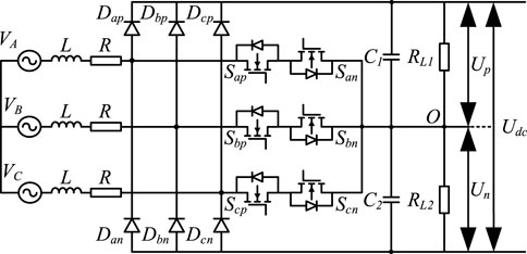
FIGURE 1. Topology of VIENNA rectifier.
When the switch is on, the input current passes through the left switch and the right diode in turn. The boost inductor stores energy, and the right switch works in the synchronous rectification state. When the switch is off, the state of diode depends on the direction of input current. The boost inductor releases energy, and the inductor current is reduced. It is necessary to control the output in each phase. There is no switch straight-through problem, which can avoid the distortion of the grid-side current at zero-crossing.
During the operation of dc-link capacitors, the capacitor voltage and the thermal effect generated by the ripple current are the main factors to affect the lifetime of the capacitors. The increasing of the power loss and heat of the capacitor in the operation affects the lifetime of the capacitor. In order to predict the lifetime of dc-link capacitors, the electrical parameters should be accurately calculated. The parameters of the VIENNA rectifier are listed in Table 1.
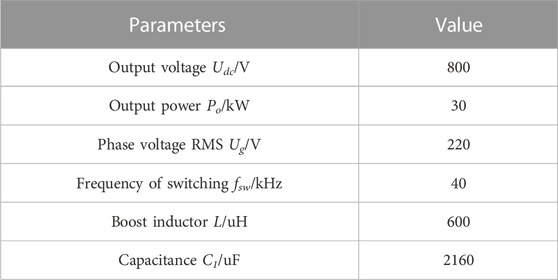
TABLE 1. The operating parameters of VIENNA rectifier.
Since the dc-link capacitor consists of two capacitor banks in series, and each capacitor bank is subjected to half of the output voltage. The output current of the VIENNA rectifier can be written as
As can be decomposed into low-frequency component and high-frequency component (Wang et al., 2020), the ripple current of capacitors can be expressed as
where ICLF and ICHF are the low frequency current component and high frequency current component of the ripple current, which can be expressed as (3) and (4) (Wang et al., 2017). Accordingly, the ripple current through the dc-link capacitor can be calculated.
According to the data of Table 1, IC = 28.43 A, ICLF = 8.8 A and ICHF = 27.03 A. Therefore, the lifetime prediction of dc-link capacitor should focus on the influence of ICHF on power loss and lifetime.
In addition, based on the calculated electrical stress, a suitable capacitor model can be selected for the dc-link of EV charging module. Since the ripple current is large, the capacitor bank with 12 capacitors can be connected in parallel to share the ripple current equally. The bank not only reduces the current stress on a single capacitor, but also reduces the size of the dc-link capacitor. Finally, an Al-caps of model EPCOS B43541C5187M0 is selected as the dc-link capacitor. The capacitor parameters are shown in Table 2.
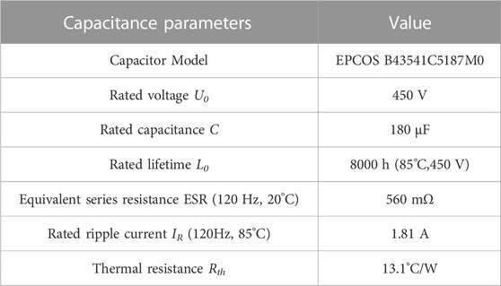
TABLE 2. Basic parameters of Al-caps.
According to the parameters shown in Table 1 and Table 2, the simulation of VIENNA can be built. The RMS value of ripple current is 29.5 A, consistent with the theoretical calculation of IC. Figure 2 shows the frequency characteristics of ripple current for individual capacitors. The ripple current of the dc-link capacitor is mainly concentrated around the frequency of switching (40 kHz) except for the third harmonic (I150Hz, rms = 0.2 A), whose RMS value is 2.2 A.
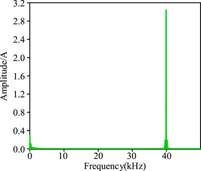
FIGURE 2. Frequency characteristics of capacitor current.
The Al-caps can be equated to a capacitor and resistor in series according to its electrical characteristics. Based on the electrical model, the power loss of the capacitor, the thermal conductivity and the ambient temperature are equivalent to the excitation, the thermal resistance and the ground potential, respectively. The electrothermal model of Al-caps is shown in Figure 3. Through the electrothermal model, the heat flow inside the capacitor can be simulated, and the temperature of each node of the capacitor can be calculated. In Figure 3, PC,loss is the power loss generated by ESR; Th is the hotspot temperature of capacitor; Tc is the case temperature of capacitor; Ta is the ambient temperature; Rthhc is the thermal resistance from the capacitor hotspot to the case; Rthca is the thermal resistance from the capacitor case to the external environment; Rth is the sum of Rthhc and Rthca, whose values are usually available in the datasheet. When the Al-caps is operating, the power loss generated by the ESR in the electrical model is input to the thermal model as the thermal excitation, which generates heat on the thermal resistance and makes the capacitor hotspot temperature rise.
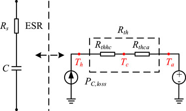
FIGURE 3. Electrothermal model of Al-caps.
According to Figure 3, the power loss PC,loss and hotspot temperature Th of the capacitor can be expressed as
where IC,rms is the RMS value of ripple current and RESR is the equivalent series resistance value of the capacitor.
According to (5) and (6), the RMS value derived from the time expression of the capacitor ripple current can be applied to calculate the capacitor hotspot temperature. This method considers both capacitor ESR and thermal resistance as constant values. However, the ESR and Rth are affected by the capacitor hotspot temperature, ripple frequency, and thermal measures, respectively. As a result, with the RMS value of the ripple current, the calculation method remains an error in the actual situation. Therefore, in order to improve the accuracy, it is necessary to propose a hotspot temperature calculation method of Al-caps which integrates the frequency characteristics of ripple current and thermal dissipation environment.
In practice, the ripple current contains many current components of different frequency, and they have different effects on the temperature of capacitor due to the dielectric losses produced by the dielectric alumina that are influenced by the changing electric field. The frequency characteristics of ESR is shown in Figure 4.
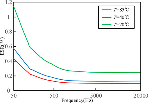
FIGURE 4. The frequency characteristics of ESR.
Hence the effect of current frequency can be expressed by the frequency factor of rated ripple current kf, as shown in Table 3. The principle of kf is that the ripple current of different frequencies and the ripple current of 120 Hz produce the same heat generation, i.e., the same power loss.

TABLE 3. Frequency Factor of Rated Ripple Current kf.
Given by the manufacturer in the capacitor manual the kf is the conversion factor to convert the ripple current of different frequency to reference frequency. Considering the effect of current frequency on the hotspot temperature, Eq. 5 can be written as
where,
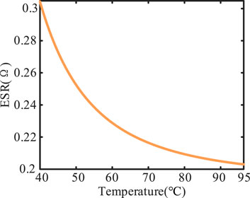
FIGURE 5. The temperature characteristics of ESR (fst = 120 Hz).
In order to operate without exceeding the maximum temperature allowed, it is necessary to install an air-cooled heat sink or other thermal dissipation measures to transfer the heat generated by the capacitor to the environment. The effect of air speed on hotspot temperature is mainly reflected in two aspects. On the one hand, the heat sink leads to dissipate heat faster and slows down the decrease tendency of ESR caused by increasing temperature. On the other hand, the heat sink affects the internal thermal conductivity of the capacitor, which affects the capacitor thermal resistance. The effect of air speed on thermal resistance can be described by a rational function (Stevens et al., 1996; Huesgen, 2014), and the mathematical model can be shown as (8).
where ν is the air speed of heat sink; Rth(ν) is the thermal resistance of the capacitor at the air speed of v m/s, which indicates the thermal conductivity of the capacitor. And the value of Rth is affected by the material characteristics, geometry and thermal dissipation of capacitors. The parameters of a and b can be obtained from the thermal resistance data provided in the capacitor manual. The air speed-thermal resistance model of capacitor EPCOS B43541C5187M0 can be shown in Figure 6.
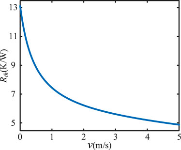
FIGURE 6. The air speed-thermal resistance model of capacitor EPCOS B43541C5187M0.
When the air speed is in the range of 0–2 m/s, it has an extremely significant effect on the thermal resistance. When the air speed is greater than 2 m/s, it has less impact.
Considering the effect of thermal dissipation on the hotspot temperature, Eq. 6 can be rewritten as
Combining (7) and (9), dc-link capacitor hotspot temperature Th calculation model can be built as (10). Thus, it is realized about the hotspot temperature calculation method of Al-caps considering the frequency characteristics of ripple current and thermal dissipation.
As shown in Figure 2, the ripple current is taken as the input to verify the accuracy of the proposed method. With the application of the calculation method with RMS shown in (5), 6 and the calculation method of Al-caps proposed in this paper as (9), the hotspot temperature is calculated when the ambient temperature is in the range of 85°C–40°C. The accuracy of the calculated value is compared with the actual value provided by TDK manufacturer, and the comparison results are shown in Figure 7.
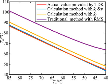
FIGURE 7. The comparison results between different hotspot temperature models.
In Figure 7, certain errors exist in the result of traditional hotspot temperature calculation method with RMS compared with the actual calculation results provided by the manufacturer. However, the average error is greater than 15°C. By introducing the frequency factor kf on the basis of the traditional method, the error of the calculation result is reduced, and the average error is less than 4°C. The calculation accuracy is significantly improved. In addition, based on the calculation method considering kf, by introducing the air speed ν of heat sink, the deviation caused by the change of thermal dissipation is eliminated, and the average error is reduced to within 1°C, which further improves the accuracy of hotspot temperature calculation.
With the data of a charging device in Nanjing 2020 as the ambient temperature profile, the hotspot temperature curve is shown in Figure 8. When the air speed increases from 0 m/s to 2 m/s, the hotspot temperature and temperature rise generated by the ripple current decrease. Therefore, the magnitude of the temperature rise depends on the magnitude of the capacitor ripple current and the thermal dissipation. The smaller ripple current or the faster air speed causes the smaller temperature rise of the capacitor; the larger ripple current or the slower air speed causes the larger temperature rise of the capacitor.
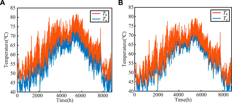
FIGURE 8. DC-link capacitors hotspot temperature curve of a charging device in Nanjing 2020: (A) without the air speed v, (B) with the air speed v (v = 2 m/s).
According to the simulation results above, the proposed hotspot temperature calculation method has high accuracy and applicability when applied to discrete temperature or continuous temperature profiles for a long time. It can realize real-time continuous hotspot temperature calculation of dc-link capacitors in charging equipment. By calculating the hotspot temperature, the basis for reliability analysis and lifetime prediction of dc-link capacitor can be established.
The process of lifetime prediction for Al-caps in EV charging module is shown as Figure 9. Firstly, by deconstructing the stress under the operation state of capacitors, mission profiles are monitored, such as ambient temperature, thermal dissipation, ripple current and operation voltage. Meanwhile, the electrothermal model is established by calculating electrical parameters such as ESR and power loss based on the ambient temperature profile and the frequency factor of capacitor current. Then, the thermal resistance can be solved by combining the electrothermal model and thermal dissipation. The hotspot temperature is calculated when used as the input data for calculating ESR in the next moment. Then, the data of ambient temperature and the hotspot temperature are used to calculate the lifetime of capacitors at the reference voltage by the lifetime model of Al-caps under constant voltage fitted with discrete lifetime data. Finally, the correction factor of voltage is introduced to construct a multi-lifetime model which can be used to calculate lifetime of Al-caps at any voltage. And the reliability of Al-caps can be analysed by Weibull distribution with two parameters.
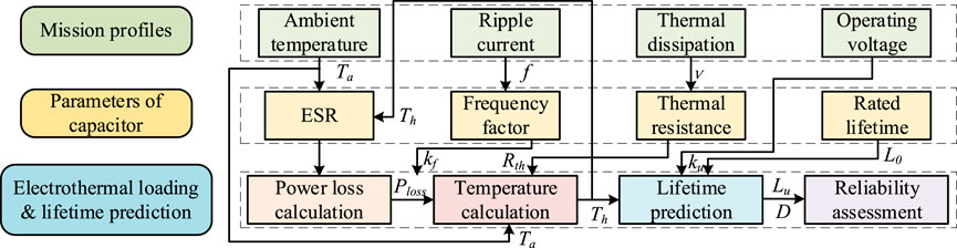
FIGURE 9. The process of lifetime prediction for Al-caps in EV charging module.
Lifetime models are the basis for condition monitoring and lifetime prediction of capacitors. A leading global manufacturer of power electronics devices, TDK, considers operating voltage, ripple current, ambient temperature and thermal conditions as important factors to affect the lifetime of capacitors. Thermal dissipation affects hotspot temperature and lifetime by influencing thermal resistance. Thus, a multi-life model of Al-caps is the key to improve the accuracy of lifetime prediction by the quantitative effects of voltage, current and temperature.
With the discrete lifetime data of capacitors provided by manufacturers, the following conclusion can be drawn: the ambient temperature and hotspot temperature determine the capacitor life at the same voltage. As a result, an ambient temperature-hotspot temperature-lifetime model shown in (11) and (12) can be established to describe the effects of ambient temperature profile and ripple current on lifetime of capacitors at constant voltage.
where L (Ta, Th) is the lifetime of capacitors under one of mission profiles; L0 is the lifetime of under the rated mission profile, which is usually listed in the usage information of capacitor; f (Ta, Th) is a polynomial function describing the effect of ambient temperature and hotspot temperature on the lifetime. And the coefficient a can be fitted by the discrete lifetime data provided by the capacitor manufacturer. The lifetime model of capacitor EPCOS B43541C5187M0 under constant voltage is shown in Figure 10. The lifetime of capacitors decreases with the increase of hotspot temperature at the same ambient temperature. The lifetime of capacitors decreases with the decrease of ambient temperature at the same hotspot temperature. After determining the hotspot temperature and ambient temperature at the same voltage, the lifetime of capacitors can be obtained under this operating condition.
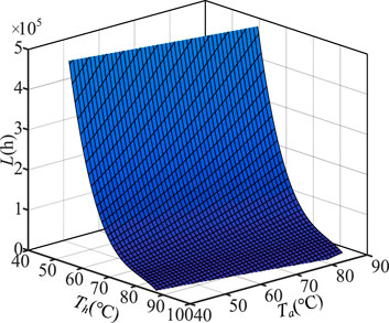
FIGURE 10. The lifetime model of capacitor under constant voltage.
The lifetime model above considers the ambient temperature and ripple current under constant voltage conditions. In practice, when the operating mode of the converter changes, the voltage stress applied on the capacitors change accordingly. When the capacitor is under a high voltage stress, the lifetime of capacitor decreases with increasing operating voltage. When the voltage is low, the lifetime of capacitor can be regarded as unaffected by the voltage change. In this paper, by introducing the voltage correction factor ku, a polynomial model of operating voltage-ripple current-voltage correction factor ku is established to describe the effect of operating voltage variation on lifetime, as shown in (13) and (14).
where Lu (Ta, Th) is the lifetime under operating voltage U; I is the RMS value of total ripple current, the parameter b can be obtained by fitting the lifetime data from the manuals. The voltage correction factor ku of capacitor EPCOS B43541C5187M0 is shown in Figure 11 with the reference voltage U = 400 V. In Figure 11, the voltage correction factor ku decreases with the increase of operating voltage under the same ripple current. When the voltage of Al-caps is higher than the reference voltage, the ku increases with the increase of ripple current; When the voltage of Al-caps is lower than the reference voltage, the ku decreases with the increase of ripple current. The reason is that the effect of voltage on lifetime is smaller than ripple current, when the ripple current stress is high. The most important factor to limit the lifetime of Al-caps is the ripple current by this time. The value of ku is related to the operating voltage, ripple current and reference voltage. To improve the accuracy of ku, the average value of the voltage affecting the lifetime is generally selected as the reference voltage.
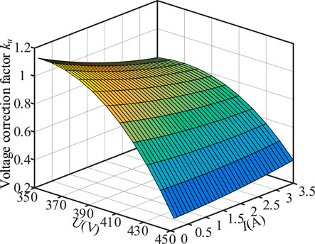
FIGURE 11. A model of operating voltage-ripple current-voltage correction factor.
Combining (11) and (13), the multi-lifetime model of capacitor can be obtained as
The multi-lifetime model above enables real-time lifetime calculation of Al-caps in EV charging modules with multiple mission profiles.
The most widely used empirical model for capacitors (Wang and Blaabjerg, 2014; Huang et al., 2018; Niu et al., 2018; Sangwongwanich et al., 2021) is shown in (16), which describes the effect of temperature and voltage stress on lifetime.
where L is the lifetime of capacitors; L0 is the lifetime of capacitors under test conditions; U is the voltage of capacitors; U0 is the voltage of capacitors under test conditions; T is the Kelvin temperature of capacitors; T0 is the test Kelvin temperature of capacitor; Ea is the activation energy; KB is the Boltzmann constant (8.62 × 10⁻⁵ eV/K); and n is the index of voltage. The values of Ea and n are the key parameters in the model by fitting.
For Al-caps, when Ea = 0.94 eV, Eq. 17 can be simplified as
According to the data provided by manufacturers of capacitors, the voltage stress index of Al-caps n1 is in the range of 3–5. The larger value of n1 is, the more sensitive the lifetime of Al-caps is to voltage stress. However, the general lifetime model above is not sufficient to define the stress on the capacitor comprehensively. There is a large error when the charging module operating condition changes.
In order to verify the accuracy of the lifetime model under constant voltage, the lifetime of capacitor EPCOS B43541C5187M0 in Table 2 is calculated at U = 400 V with the general lifetime model in (17) (n1 = 4.546, n2 = 7.47) and the lifetime model under constant voltage in (11). The results are compared with the lifetime data provided by the manufacturer (ignoring the condition of lifetime greater than 250000 h). The comparison results are shown in Figure 12. It is clear that the proposed lifetime model has the highest calculation accuracy when the capacitor is working at the rated temperature of 85°C. As the ambient temperature decreases, the error of the lifetime model under constant voltage gradually increases, and the maximum error is about 6.7%. In the full range of ambient temperature, the accuracy of proposed model is significantly higher than general lifetime model.
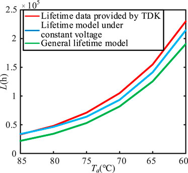
FIGURE 12. The accuracy comparison between general lifetime model and the lifetime model under constant voltage.
To verify the accuracy of the multi-lifetime model, the lifetime of capacitor EPCOS B43541C5187M0 in Table 2 is calculated at Ta = 85 °C with the general lifetime model in (17) (n1 = 4.546, n2 = 7.47) and the multi-lifetime model in (15) when the operating voltage is in the range of 450–350 V. What’s more, the accuracy was compared with the actual life data provided by the manufacturer. The comparison between general lifetime model and the multi-lifetime model (ignoring the condition of lifetime greater than 250000 h) is shown in Figure 13.
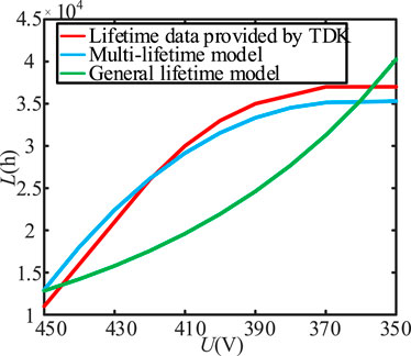
FIGURE 13. The comparison between general lifetime model and the multi-lifetime model.
In Figure 13, the multi-lifetime model proposed in this paper has the highest accuracy when the operating voltage is about 420 V. The maximum error is 2000 h when the operating voltage is the rated voltage or the minimum voltage which affects the lifetime of capacitors. The general lifetime model only has high accuracy at the operating voltage of 445 V and 360 V. In other voltage ranges, the accuracy of the proposed multi-lifetime capacitor model is greater than the general lifetime model with excellent practical application value.
The multi-lifetime model proposed in this paper can be applied to the lifetime prediction of Al-caps at any ambient temperature, operating voltage, and ripple current. For the dynamical electrothermal stresses applied to the capacitor in the mission profiles, the cumulative damage model of lifetime can be constructed with the Miner linear damage theory as shown in (18). The damage of Al-caps can be accumulated linearly. And the capacitor is damaged when the accumulated damage D = 1.
where lj is the operating time of the jth mission profile; Luj (Ta, Th) is the rated lifetime of the jth mission profile; D is the accumulated damage value of the capacitor;
Combining (15) and (18), the lifetime of Al-caps can be predicted based on the mission profiles such as ambient temperature, operating voltage and ripple current. An EV charging pile in Nanjing is selected as the research object, and the lifetime of dc-link capacitor is calculated by combining the Miner linear damage theory with the mission profiles in 2020. The result of lifetime is about 23.1 years.
Furthermore, to describe the trend of capacitor reliability, a Weibull distribution with two parameters is employed in this paper to analyze the reliability of Al-caps, as follows:
where t is the lifetime of the capacitors; η is the scale parameter; β is the shape parameter; and the shape parameter β of Al-caps is usually 5.
In this paper, the predicted lifetime is the B10 life, which is the average lifetime when the reliability is 0.9. The value of η can be calculated, on which the reliability distribution of the charging module dc-link capacitors can be obtained. The reliability distribution of capacitor is shown in Figure 14.
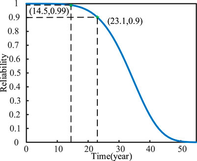
FIGURE 14. The reliability distribution of dc-link capacitor in charging module.
In Figure 14, the lifetime of B1 (damage rate of 1%) can be calculated as 14.5 years, and the lifetime of B10 (damage rate of 10%) is 23.1 years.
The accuracy of lifetime prediction is mainly constrained by hotspot temperature calculation method and lifetime model, which cannot meet the accuracy requirements of charging modules under different operating conditions. This paper has proposed a hotspot temperature calculation method and lifetime model based on charging module mission profiles. The effectiveness is verified with 30 kW EV charging module. The main conclusions are as follows.
1) A hotspot temperature calculation method is proposed considering the amplitude-frequency characteristics of ripple current and the thermal dissipation conditions. By introducing the frequency factor of rated ripple current kf and the air speed of heat sink ν, the effect of ripple current frequency on power loss is described; the temperature deviation caused by the change of thermal dissipation condition is eliminated; the accuracy of hotspot temperature calculation is improved.
2) The hotspot temperature calculation result is fed back to calculate ESR at the next moment, which eliminates the influence of hotspot temperature on ESR and further improves the accuracy of hotspot temperature calculation.
3) The lifetime model of capacitor under constant voltage and the multi-lifetime model are constructed by the curve fitting toolbox in MATLAB, which have higher accuracy compared with the general lifetime model and provide a theoretical basis for the actual operation and reliability design of EV charging device.
The original contributions presented in the study are included in the article/Supplementary Material, further inquiries can be directed to the corresponding author.
The writing of the methodology is mainly carried out by HL and MZ. JQ is responsible for simulation verification in the paper. The supervision, review and editing of the papers are mainly carried out by WZ, ZD, and LC. All authors contributed to the article and approved the submitted version.
This research was funded by Science and Technology Project of State Grid Corporation 52094021N00S.
Author ZD was employed by State Grid Shanghai Municipal Electric Power Company. Author LC was employed by State Grid Electric Power Research Institute and State Grid Nanrui Technology Co., LTD.
The remaining authors declare that the research was conducted in the absence of any commercial or financial relationships that could be construed as a potential conflict of interest.
The authors declare that this study received funding from State Grid Corporation. The funder had the following involvement in the study: Nanjing temperature data collection and partial analysis of the article.
All claims expressed in this article are solely those of the authors and do not necessarily represent those of their affiliated organizations, or those of the publisher, the editors and the reviewers. Any product that may be evaluated in this article, or claim that may be made by its manufacturer, is not guaranteed or endorsed by the publisher.
The Supplementary Material for this article can be found online at: https://www.frontiersin.org/articles/10.3389/felec.2023.1226006/full#supplementary-material
Agarwal, N., Ahmad, M. W., and Anand, S. (2018). Quasi-online technique for health monitoring of capacitor in single-phase solar inverter. IEEE Trans. Power Electron. 33 (6), 5283–5291. doi:10.1109/TPEL.2017.2736162
Al-Hanahi, B., Ahmad, I., Habibi, D., and Masoum, M. A. S. (2021). Charging infrastructure for commercial electric vehicles: challenges and future works. IEEE Access 9, 121476–121492. doi:10.1109/ACCESS.2021.3108817
An, L., and Lu, D. D. (2016). Analysis of dc bus capacitor current ripple reduction in basic DC/DC cascaded two-stage power converters. IEEE Trans. Ind. Electron. 63 (12), 7467–7477. doi:10.1109/TIE.2016.2594162
Blaabjerg, F., Wang, H., Vernica, I., Liu, B., and Davari, P. (2021). Reliability of power electronic systems for EV/HEV applications. Proc. IEEE 109 (6), 1060–1076. doi:10.1109/JPROC.2020.3031041
Huang, S., Xiong, S., Zeng, D., Qu, L., Nie, L., and Zhu, G. (2018). “Accurate lifetime predication of aluminum electrolytic capacitor considering equivalent series resistance variations,” in Proc. IEEE PEAC Conf., Shenzhen, China, 04-07 November 2018, 1–5.
Huesgen, T. (2014). Thermal resistance of snap-in type aluminum electrolytic capacitor attached to heat sink. IEEE Trans. Ind. Appl. 50 (2), 1198–1205. doi:10.1109/TIA.2013.2278420
Lledó-Ponsati, T., Bahman, A. S., Iannuzzo, F., Montesinos-Miracle, D., and Galceran-Arellano, S. (2021). Thermal modeling of large electrolytic capacitors using FEM and considering the internal geometry. IEEE J. Emerg. Sel. Top. Power Electron. 9 (5), 6315–6328. doi:10.1109/JESTPE.2021.3089899
Niu, H., Wang, S., Ye, X., Wang, H., and Blaabjerg, F. (2018). Lifetime prediction of aluminum electrolytic capacitors in LED drivers considering parameter shifts. Microelectron. Reliab. 88 (90), 453–457. doi:10.1016/j.microrel.2018.06.027
Sangwongwanich, A., Shen, Y., Chub, A., Liivik, E., Vinnikov, D., Wang, H., et al. (2021). Design for accelerated testing of dc-link capacitors in photovoltaic inverters based on mission profiles. IEEE Trans. Ind. Appl. 57 (1), 741–753. doi:10.1109/TIA.2020.3030568
Shen, Y., Chub, A., Wang, H., Vinnikov, D., Liivik, E., and Blaabjerg, F. (2019). Wear-out failure analysis of an impedance-source PV microinverter based on system-level electrothermal modeling. IEEE Trans. Ind. Electron. 66 (5), 3914–3927. doi:10.1109/TIE.2018.2831643
Stevens, J. L., Sauer, J. D., and Shaffer, J. S. (1996). “Modeling and improving heat dissipation from large aluminum electrolytic capacitors,” in IAS '96 Meeting, San Diego, United States, 06-10 October 1996, 1343–1346.
Sun, B., Fan, X., Yuan, C. A., Qian, C., and Zhang, G. (2015). “A degradation model of aluminum electrolytic capacitors for LED drivers,” in Proc. 16th ICTMMSEM Conf., Budapest, Hungary, 19-22 April 2015, 1–4.
Wang, H., and Blaabjerg, F. (2014). Reliability of capacitors for dc-link applications in power electronic converters—An overview. IEEE Trans. Ind. Appl. 50 (5), 3569–3578. doi:10.1109/TIA.2014.2308357
Wang, H., Huang, S., Kumar, D., Wang, Q., Deng, X., Zhu, G., et al. (2021). Lifetime prediction of dc-link capacitors in multiple drives system based on simplified analytical modeling. IEEE Trans. Power Electron. 36 (1), 844–860. doi:10.1109/TPEL.2020.3003236
Wang, Q., Zhang, J., Zhang, M., Hu, X., Ding, G., Jiang, M., et al. (2017). Cimicifugamide from Cimicifuga rhizomes functions as a nonselective β-AR agonist for cardiac and sudorific effects. Power Electron. 51 (9), 122–130. CNKI:SUN:DLDZ.0.2017-09-036. doi:10.1016/j.biopha.2017.03.058
Wang, T., Chen, C., Liu, T., Chao, Z., and Duan, S. (2020). Current ripple analysis of three-phase Vienna rectifier considering inductance variation of powder core inductor. IEEE Trans. Power Electron. 35 (5), 4568–4578. doi:10.1109/TPEL.2019.2944853
Wen, H., Xiao, W., Wen, X., and Armstrong, P. (2012). Analysis and evaluation of dc-link capacitors for high-power-density electric vehicle drive systems. IEEE Trans. Veh. Technol. 61 (7), 2950–2964. doi:10.1109/TVT.2012.2206082
Zeng, W., Jie, G., Zou, J., Guo, L., Gan, W., Li, J., et al. (2020). “Research on reliability of dc charging pile based on analysis of internal function,” in Proc. AEEES Conf., Chengdu, China, 29-31 May 2020, 318–322.
Zhao, Z., Zhou, D., Davari, P., Fang, J., and Blaabjerg, F. (2021). Reliability analysis of capacitors in voltage regulator modules with consecutive load transients. IEEE Trans. Power Electron. 36 (3), 2481–2487. doi:10.1109/TPEL.2020.3016902
Keywords: dc-link capacitor, calculation method of hotspot temperature, lifetime model, VIENNA rectifier, reliability analysis
Citation: Liu H, Qiu J, Zhang W, Zhang M, Dou Z and Chen L (2023) Lifetime prediction and reliability analysis for aluminum electrolytic capacitors in EV charging module based on mission profiles. Front. Electron. 4:1226006. doi: 10.3389/felec.2023.1226006
Received: 20 May 2023; Accepted: 28 July 2023;
Published: 16 August 2023.
Edited by:
Terence O'Donnell, University College Dublin, IrelandReviewed by:
Hamed Heydari-doostabad, University College Dublin, IrelandCopyright © 2023 Liu, Qiu, Zhang, Zhang, Dou and Chen. This is an open-access article distributed under the terms of the Creative Commons Attribution License (CC BY). The use, distribution or reproduction in other forums is permitted, provided the original author(s) and the copyright owner(s) are credited and that the original publication in this journal is cited, in accordance with accepted academic practice. No use, distribution or reproduction is permitted which does not comply with these terms.
*Correspondence: Wei Zhang, emhhbmdfd2VpQG5lZXB1LmVkdS5jbg==
Disclaimer: All claims expressed in this article are solely those of the authors and do not necessarily represent those of their affiliated organizations, or those of the publisher, the editors and the reviewers. Any product that may be evaluated in this article or claim that may be made by its manufacturer is not guaranteed or endorsed by the publisher.
Research integrity at Frontiers
Learn more about the work of our research integrity team to safeguard the quality of each article we publish.