- College of Electrical Engineering and Control Science, Nanjing Tech University, Nanjing, China
The wireless power transmission (WPT) system through magnetic field coupling for energy transmission may have foreign objects in the transmission channel in the practical application process, which brings hidden dangers to the WPT system. In this article, a WPT system without and with foreign objects is constructed. The influence of foreign objects on self-inductance and mutual-inductance of coupling coils is studied from the aspects of foreign object height, radius, transmission distance, and coil turns. Then, by constructing the circuit topology of the series structure, the influence of foreign objects on the transmission efficiency and the phase difference between voltage and current of the system is studied, and finally the influence law of metal foreign objects on the performance of the WPT system is summarized.
1 Introduction
Since mankind entered the electrical age, people’s lives have been inseparable from “electricity.” Nowadays, with the emergence and upgrading of various electric equipment, people have more and more demands for electric energy, and the degree of electrification is getting higher and higher. The reform and innovation of electric energy transmission technology is imminent. The traditional power transmission mode is generally realized in the form of electrical contact through transmission media such as metal wires, but the traditional power transmission mode inevitably has problems such as requiring manual insertion and extraction. Therefore, in some special environments, the disadvantages of the traditional power transmission mode will be seen at a glance.
Wireless power transmission (WPT) technology is a technology based on non-wire connection, with the help of electromagnetic waves, microwaves, and other physical space energy carriers, to achieve power transmission from the power side to the load side (Li et al., 2017). The characteristics of wireless charging, such as charging anywhere, anytime, and charging multiple devices at the same time, make it free from the bondage of cables, which greatly increases the convenience and flexibility of power supply for power-using devices (Zhang et al., 2021).
In recent years, due to people’s desire for multi-field applications of wireless charging and high-tech, WPT technology is booming. WPT technology plays an increasingly important role in various fields around the world (S et al., 2022). With the combination of modern control theory, power electronics technology, electromagnetic field, analog electronics technology, and many other fields, WPT technology has gradually evolved into a highly comprehensive and vital technology.
Energy replenishment for electric vehicles is a common application for WPT technology (Zhang et al., 2019). The energy transmission path is from the ground transmitting coil to the onboard receiving coil, but the surrounding environment usually has an impact on the system, for example, the impact of metallic foreign objects on the WPT system (Y et al., 2021). If the metal foreign object occurs in the area near the transmitting and receiving coils, the transmission power and transmission efficiency of the whole power transmission system will be affected (Shi et al., 2021). At the same time, the eddy currents generated by the intruding foreign objects can cause serious safety hazards for the system (Lu et al., 2021). It is therefore necessary to analyze the impact of foreign objects on the WPT technology.
Zhang et al. (2022) classify many new foreign object detection technologies emerging at present into three categories: auxiliary coil foreign object detection technology, system parameter foreign object detection technology, and sensor foreign object detection technology, and analyze their basic principles, solve technical problems and detection categories one by one, and compare the characteristics of the three detection technologies. The cost of the system parameter detection method based on electrical parameters is relatively low, and no additional equipment is needed (Sonnenberg et al., 2019; Meng et al., 2021; Son et al., 2021). A foreign body detection (FOD) method based on a symmetrical coil group is proposed to prevent the wireless power transmission (WPT) system fever, which may cause accidental fires (Xiang et al., 2019). A metal object detection (MOD) circuit with non-overlapping coils is proposed to ensure the safe operation of wireless EV chargers (Jang et al., 2016). A metal object detection system, which is based on mistuned resonant circuits and utilizes the variation of self-inductance of a sensing pattern, is proposed for wireless electric vehicle chargers (Jeong et al., 2018). However, it is necessary to identify foreign objects according to the action law of foreign objects on the system. Therefore, it is necessary to conduct in-depth research on the influence of foreign objects on wireless power transmission systems and summarize the influence law of foreign objects from the two aspects of coupling parameter change and system parameter change, so as to lay the foundation for the realization of the system parameter detection method based on electrical parameters.
In this article, first, the influence of the size of the metal foreign body and the number of turns of the coil on the coupler parameters of the WPT system and the coil transmission distance is studied. Second, the influence of the change of the metal foreign body parameters on the transmission performance of the system, including efficiency and phase difference, is studied by establishing a topological performance calculation model. Finally, the changing characteristics of the WPT system containing foreign objects are summarized, which provides a reference for the detection and identification of metal foreign objects.
2 Influence of foreign objects on coupler parameters
2.1 Three-dimensional model establishment of the coupler
2.1.1 Coupler model without foreign objects
In order to study the influence of metal foreign objects on the coupler parameters of the wireless power transmission system, this article establishes a three-dimensional electromagnetic simulation model of the coupler coil as shown in Figure 1. The parameters of the coupler are centered on (0, 0, 0). Both the transmitting coil and the receiving coil have an outer diameter of 20 cm, inner diameter of 10 cm, and thickness of 1 cm, and the transmission distance D between the two coils is set to 16 cm for the XY plane symmetric copper ring column when Z = 0. At the same time, in order to be closer to the actual situation, the iron core and aluminum separator are established: the outermost side of the two coils is attached to a loss-free soft iron core with a radius of 20 cm and a thickness of 2 cm, and the permeability is 3,000; a 60 × 60 × 1 cm aluminum separator is placed outside the two cores to shield magnetic field radiation.
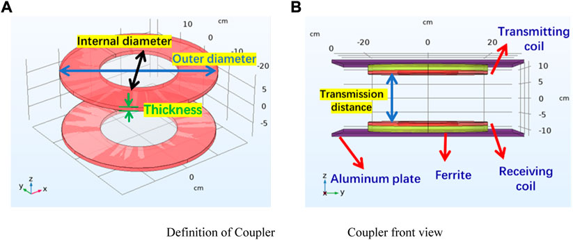
FIGURE 1. Three-dimensional structure of the coupler. (A) Definition of the coupler. (B) Front view of the coupler.
The parameters of the coupler coil in the absence of foreign objects can be obtained from the calculations of 3D electromagnetic simulation commercial software as shown in Table 1.
2.1.2 Coupler model with foreign objects
The metal foreign object model is based on a common aluminum can as an example. The 3D simulation model containing the metallic foreign object is shown in Figure 2. The metal foreign object model is a hollow circular can with an outer diameter of 8 cm, an inner diameter of 6 cm, and a height of 12 cm. The whole hollow can is still centered at (0, 0, 0) and symmetrical about the XY plane at Z = 0. The distance between the two coils of transmission is 16 cm.
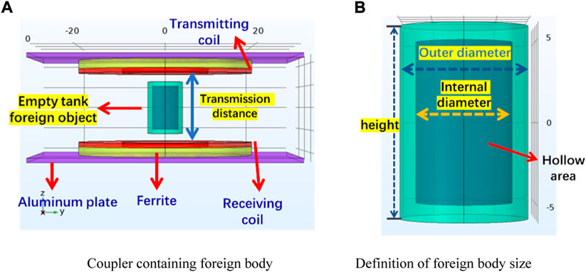
FIGURE 2. Coupler model with foreign objects. (A) Coupler containing a foreign body. (B) Definition of foreign body size.
2.2 Influence of foreign object height change
In order to obtain the influence of the metal foreign object on the parameters of the system coupler when the height of the foreign object changes, the radius r of the metal foreign object is set to 10 cm, the transmission distance between the coils is 24 cm, and the number of turns of the coil is 14. The initial value of the height of the foreign object is set to 4 cm, the termination value is 20 cm, and the step length is 4 cm for parametric scanning. When the height is different, the magnetic flux density of the foreign object obtained is shown in Figure 3. The size of the foreign body refers to the metal Coca-Cola can. H is the height of the can.
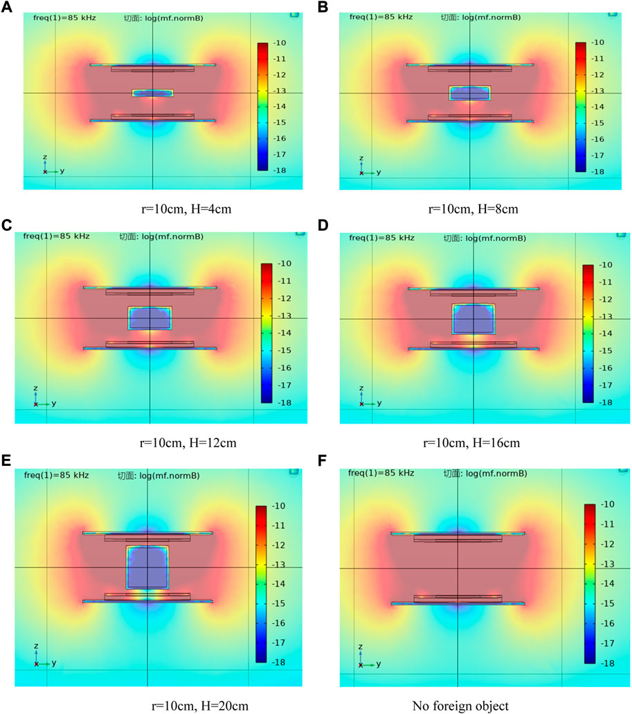
FIGURE 3. Magnetic flux density of the coupler when the height of the foreign object changes. (A) r = 10 cm and H = 4 cm. (B) r = 10 cm and H = 8 cm. (C) r = 10 cm and H = 12 cm. (D) r = 10 cm and H = 16 cm. (E) r = 10 cm and H = 20 cm. (F) No foreign object.
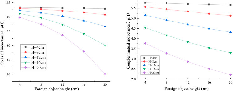
The observation shows that with the increase in the height of the metal foreign object, the magnetic flux density color in the area below the metal foreign object gradually changes from red to yellow and then to light blue, that is, the magnetic flux density decreases from large to small, and the greater the height, the more obvious the change of the magnetic flux density. Similarly, the variation of coil self-inductance and coupling mutual inductance parameters can be obtained by the aforementioned simulation as shown in Figure 4. H is the height of the can.
When the radius r of the metal foreign object is constant and only the height changes, the self-inductance of the coil and the mutual inductance of the coupler decrease with the increase in the foreign object height. When the height of the metal foreign object is larger, the greater the slope change in the coil self-inductance point line diagram is, the greater the degree of coil self-inductance decline is, and the more obvious the change is. The smaller the slope change of the mutual inductance point line diagram between the coils is, the less obvious the change is.
2.3 Influence of foreign object radius change
In this section, in order to obtain the influence of the metal foreign object on the system coupler parameters when the foreign object radius (i.e., half of the outer diameter) is changed, the height H of the metal foreign object is set to 12 cm, the transmission distance between coils is 24 cm, the number of turns of coils is 14, the radius of the foreign object is set to R, the starting value of R is 2 cm, the ending value is 10 cm, and the step size is 2 cm for parameterization. When the radius of the foreign object is different, the magnetic flux density of the foreign object obtained is shown in Figure 5.
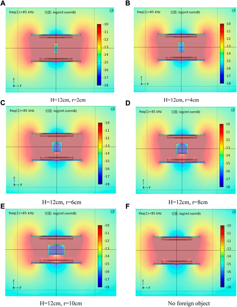
FIGURE 5. Magnetic flux density of the coupler changes when the height of the foreign object changes. (A) H = 12 cm, r = 2 cm. (B) H = 12 cm, r = 4 cm. (C) H = 12 cm, r = 6 cm. (D) H = 12 cm, r = 8 cm. (E) H = 12 cm, r = 10 cm. (F) No foreign object.
Through observation, it can be seen that with the increase in the radius of the metal foreign object, the magnetic field color in the area directly below the metal foreign object gradually changes from red to yellow, that is, the magnetic field strength changes from large to small, and when the radius is larger, the degree of change in the magnetic field is more obvious.
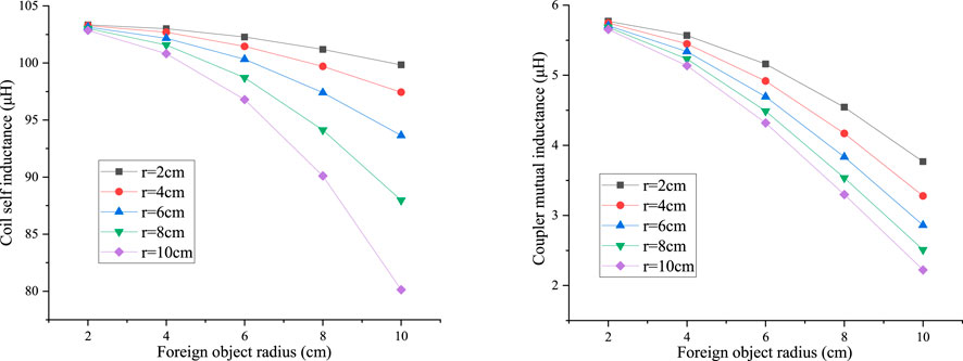
In order to study the change law of coupler coil parameters when the height of metal foreign objects is constant and the radius is changed, the parameter changes of coil self-inductance and mutual inductance when the height is constant and the radius is changed are obtained through three-dimensional simulation, and the point line diagram is drawn, as shown in Figure 6.
When the height h of the metal foreign object is constant and only the radius changes, with the increase in the radius of the foreign body, the coil self-inductance and inter-coil mutual inductance at each constant height will decrease, and the larger the radius of the metal foreign object is, the greater the slope change of the coil self-inductance and inter-coil mutual inductance point line graph is, that is, the greater the decrease degree of the coil self-inductance and inter-coil mutual inductance is, and the more obvious the change is. Comparing the point line diagrams of different constant heights, it is found that when the constant height increases, the coil self-inductance and mutual inductance decrease faster and more obviously with the increase in the radius.
2.4 Influence of transmission distance variation of the coupler with foreign objects
When studying the influence of the transmission distance variation of the coupler with foreign objects, the outer diameter, inner diameter, and height of the metal foreign object are set to 8 cm, 6 cm, and 12 cm, respectively. The size of the coupler coil is same as shown in Section 2.1.1. Referring to the ground clearance of the electric vehicle chassis, the transmission distance between the transmitting coil and the receiving coil is in the range of 140–240 mm. Therefore, in this study, the initial value of transmission distance D is set to 14 cm, the final value is 24 cm, and the step length is 2 cm. The magnetic flux density distribution of the coupler under different transmission distances is shown in Figure 7.
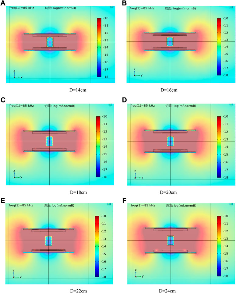
FIGURE 7. Magnetic flux density when the transmission distance of the coupler changes. (A) D = 14 cm. (B) D = 16 cm. (C) D = 18 cm. (D) D = 20 cm. (E) D = 22 cm. (F) D = 24 cm.
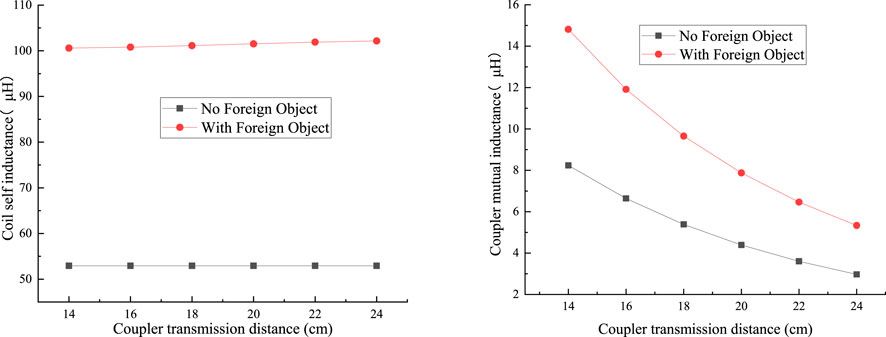
From the results of the magnetic flux density simulation, it can be seen that the farther the transmission distance, the smaller the influence of the foreign object. The change results of self-inductance and mutual-inductance shown in Figure 8 can be obtained through simulation calculation.
In the case of no foreign object, when the transmission distance of the coupler changes, the inductance of the coil is constant, and only the mutual inductance between the coil changes. With the intrusion of metal foreign objects, the coupling parameters of the system will be affected by metal foreign objects. The presence of foreign objects will increase the inductance of the coil and the mutual inductance between the coils. In both cases, with the increase in the coil spacing, the mutual inductance between the coils will decrease, and this trend is more obvious when a metal foreign object exists, but with the increase in the transmission distance, this trend tends to ease.
2.5 Influence of the change of coil turns with foreign objects
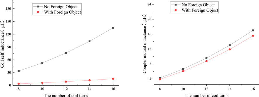
When studying the influence of the number of turns of the coupler coil containing foreign objects, the size of the metal foreign object is kept same as shown in Section 2.3. The transmission distance of the coupler is set to 16 cm, assuming that the number of turns of the coil is 8, the termination value is 16, and the step length is 2. The variation curve of coupler coil parameters can be obtained by electromagnetic simulation calculation as shown in Figure 9.
Through the analysis, it can be found that with the invasion of metal foreign objects, the coupling parameters of the system will be affected by metal foreign objects, and the presence of foreign objects will make the coil inductance and mutual inductance between coils smaller. Whether in a resonant state or non-resonant state, with the increase in the number of coil turns, the inductance value of the coil and the mutual inductance value between the coils will increase, and with the increase in the number of coil turns, the increase trend of the self-inductance of the coil with a foreign object is not obvious, but the increase trend of the mutual inductance of the coupler is similar to that without a foreign object.
3 Wireless power transmission system with foreign objects
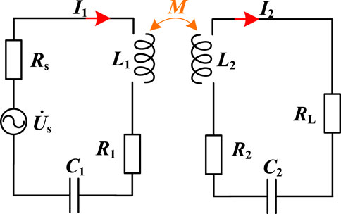
In order to analyze the influence of foreign objects on the performance of the wireless power transmission system, this article selects the most common series (SS) topology for the research study (Li et al., 2019), and its circuit topology is shown in Figure 10.
Through the analysis of circuit theoretical modeling, the transmitter current I1 and the receiver current I2 can be obtained as follows:
The receiving power of the load side is:
The system input power is:
System transmission efficiency is:
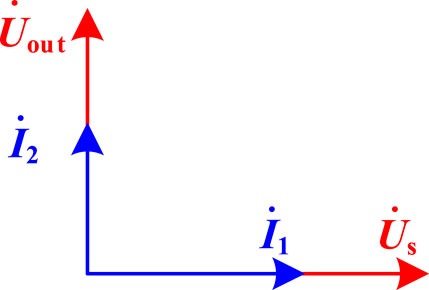
Therefore, when the WPT system is completely resonant, the phase difference between the primary current I1 and the input voltage Us is the same, and the phase difference between the secondary current I2 and the input voltage Us is 90°, as shown in Figure 11. When the input voltage Us is known, I1 and I2 are determined by the load RL and mutual inductance M. At the same time, the transmission power P of the system changes with the change in mutual inductance M and load RL.
4 Influence of foreign objects on the wireless power transmission system
To study the influence of foreign objects on the wireless power transmission system, it needs to clarify the relevant parameters of the wireless power transmission system when it works. Referring to the common working parameters of the electric vehicle wireless power transmission system, this article sets the high-frequency inverter source input at 250 V, power internal resistance at 0.1 Ω, working frequency at 85 kHz, and load resistance at 10 Ω.
4.1 Influence of the changes in foreign object height on performance
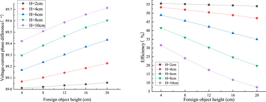
According to the height of foreign object change, the influence of the self-inductance of the coil and the mutual inductance of the coupler, the phase difference between the input current and the input voltage, and the variation curve of the system transmission efficiency can be obtained by theoretical calculation, as shown in Figure 12. H is the height of the can.
It can be seen from the figure that when the radius r of the metal foreign object is constant and only the height changes, with the increase in the height of the foreign object, the transmission efficiency of the system decreases, and the phase difference between the primary current and the input voltage increases.
4.2 Influence of the changes in foreign object radius on performance
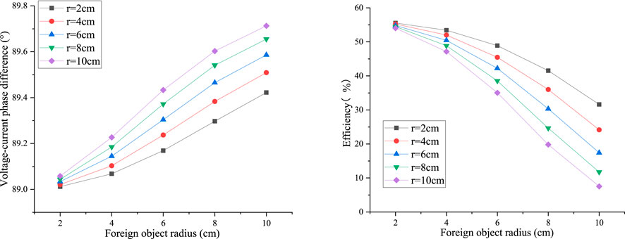
Similarly, the effect of foreign object radius on the performance of the WPT system is shown in Figure 13.
When the height H of the metal foreign object is constant and only the radius is changed, with the increase in the radius of the foreign object, the system transmission efficiency at each constant height will decrease, and the phase difference between the primary current and the input voltage will increase. With the increase in the radius of the metal foreign object, the absolute values of the system transmission efficiency and the slope of the current voltage phase difference graph will increase first and then decrease. Comparing the dot and line graphs of different constant heights, it is found that when the constant height increases, the system transmission efficiency and current voltage phase difference decrease and increase faster and more obviously with the increase in the radius.
4.3 Influence of transmission distance variation of the coupler with foreign objects on performance
According to the influence of the transmission distance change in the coupler containing foreign objects on the coil self-inductance and coupler mutual inductance, the phase difference between the input current and the input voltage and the variation curve of the system transmission efficiency can be obtained by theoretical calculation, as shown in Figure 14.
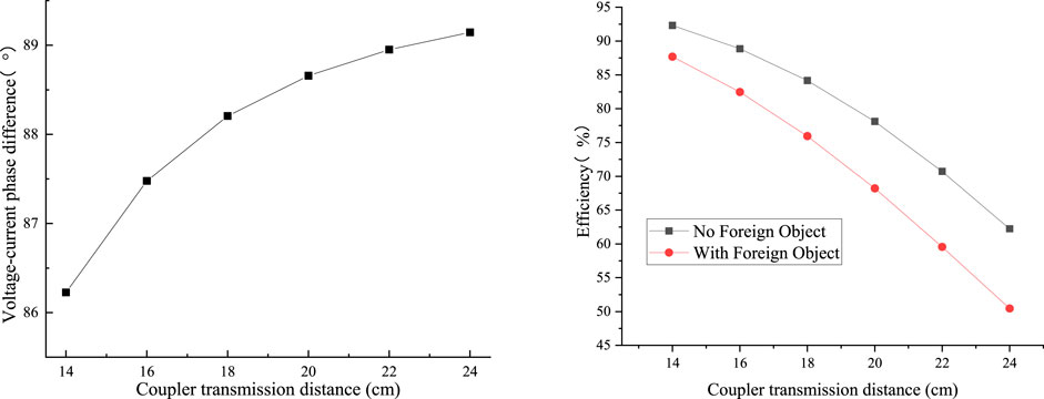
FIGURE 14. Influence of the changes in transmission distance variation of the coupler with a foreign object on performance.
In the resonant state, the primary current and input voltage of the system always remain in phase without a phase difference. With the invasion of metal foreign objects, it creates an impact on the system, resulting in a phase difference between the primary current and the input voltage. In the non-resonant state, with the increase in the transmission distance between coils, the phase difference of current and voltage increases slowly, and the increasing trend is more and more gentle. Comparing the changes in the transmission efficiency of the system under the two states of containing foreign objects or not, the transmission efficiency of the system decreases when metal foreign objects intervene in the system, which also shows that the intrusion of metal foreign objects will have a certain impact on the system. At the same time, the increase in foreign objects will significantly increase the downward trend of the system transmission efficiency.
4.4 Influence of the change in coil turns with foreign objects on performance
According to changes in coil turns of the coupler with foreign objects on coil self-inductance and mutual inductance, the phase difference between the input current and input voltage, as shown in Figure 15, and the variation curve of system transmission efficiency can be calculated by theoretical calculation.
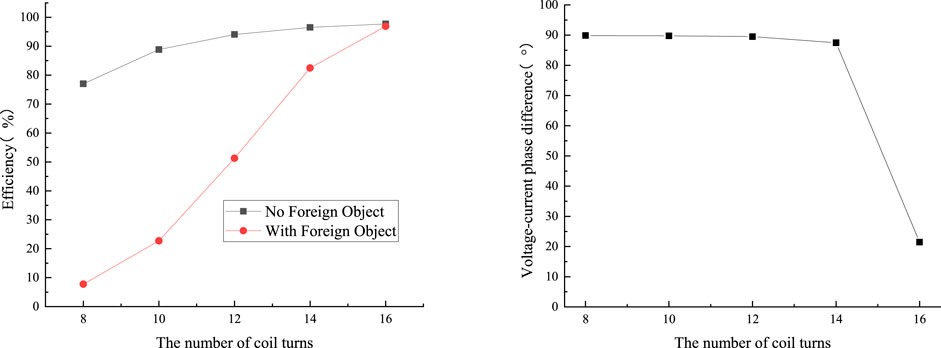
FIGURE 15. Influence of the changes in the number of coil turns with foreign objects on performance.
It can be seen from the figure that the primary current of the system always keeps the same phase with the input voltage without foreign objects, and there is no phase difference. With the intrusion of metal foreign objects, the system is affected, and the phase difference between the original current and the input voltage occurs. With the increase in the number of coil turns containing foreign objects, the phase difference between the current and voltage decreases slowly and then sharply. This is due to the increase in the number of coil turns, the mutual inductance of the coupler increases. When the turn number is 16, the increase in self-inductance caused by the increase in the number of turns of the coil and the influence of foreign objects are nearly cancelled out, so the system almost returns to the resonance state at this time. The non-resonant state caused by foreign objects is gradually offset by the increase in mutual inductance.
5 Conclusion
In this article, through three-dimensional simulation, the influence of foreign objects on the parameters and performance of the coupler in the wireless power transmission system is compared and analyzed, including three situations: the change in foreign object height and radius, the change in coupler transmission distance, and the change in the number of coupler coil turns. The invasion of metal foreign objects will reduce the transmission efficiency of the system; when the metal foreign object is large, the influence of the foreign object on the system is greater; when the transmission distance between coils is large, the transmission efficiency of the system will also be reduced. However, when the number of coil turns becomes more, the transmission efficiency of the system will be improved. The research results of this article can provide a reference for foreign object detection and recognition. When the foreign object and the coil size are reduced or increased in the same proportion, it can be applied to low-power or higher-power radio energy transmission systems.
Data availability statement
The original contributions presented in the study are included in the article/Supplementary Material; further inquiries can be directed to the corresponding author.
Author contributions
All authors listed have made a substantial, direct, and intellectual contribution to the work and approved it for publication. JL is responsible for model establishment and analysis, and YH is responsible for writing papers.
Funding
This work was supported by the Fund of Jiangsu Province Innovation and Entrepreneurship and Scientific Research Fund for Talents of Nanjing Tech University.
Conflict of interest
The authors declare that the research was conducted in the absence of any commercial or financial relationships that could be construed as a potential conflict of interest.
Publisher’s note
All claims expressed in this article are solely those of the authors and do not necessarily represent those of their affiliated organizations, or those of the publisher, the editors, and the reviewers. Any product that may be evaluated in this article, or claim that may be made by its manufacturer, is not guaranteed or endorsed by the publisher.
References
Jang, G. C., Jeong, S. Y., Kwak, H. G., and Rim, C. T. (20162016). Metal object detection circuit with non-overlapped coils for wireless EV chargers. IEEE 2nd annual southern power electronics conference (SPEC). IEEE, 1–6. 05-08 December 2016. Auckland, New Zealand.
Jeong, S. Y., Thai, V. X., Park, J. H., and Rim, C. T. (2018). Self-inductance-based metal object detection with mistuned resonant circuits and nullifying induced voltage for wireless EV chargers. IEEE Trans. Power Electron. 34 (1), 748–758. doi:10.1109/tpel.2018.2813437
Li, Y., Hu, J., Li, X., Mai, R., Li, Z., Liu, M., et al. (2019). Efficiency analysis and optimization control for input-parallel output-series wireless power transfer systems. IEEE Trans. Power Electron. 35 (1), 1074–1085. doi:10.1109/tpel.2019.2914299
Li, Z., Zhu, C., Jiang, J., Song, K., and Wei, G. (2017). A 3-kW wireless power transfer system for sightseeing car supercapacitor charge. IEEE Trans. Power Electron. 32 (5), 3301–3316. doi:10.1109/tpel.2016.2584701
Lu, J., Zhu, G., and Mi, C. C. (2021). Foreign object detection in wireless power transfer systems. IEEE Trans. Ind. Appl. 58 (1), 1340–1354. doi:10.1109/tia.2021.3057603
Meng, T., Tan, L., Zhong, R., Xie, H., and Huang, X. (2021). Research on metal foreign object detection of electric vehicle wireless charging system based on detection coil. World Electr. Veh. J. 12 (4), 203. doi:10.3390/wevj12040203
S, C., B, S., and Z, W. (2022). Overview of magnetic coupler for electric vehicles dynamic wireless charging. Trans. China Electrotech. Soc. 37 (3), 537–554.
Shi, W., Dong, J., Soeiro, T. B., and Bauer, P. (2021). Integrated solution for electric vehicle and foreign object detection in the application of dynamic inductive power transfer. IEEE Trans. Veh. Technol. 70 (11), 11365–11377. doi:10.1109/tvt.2021.3112278
Son, S., Lee, S., Rhee, J., Shin, Y., Woo, S., Huh, S., et al. (2021). “Foreign object detection of wireless power transfer system using sensor coil,” in 2021 IEEE wireless power transfer conference (WPTC) (IEEE), 1–4. 01-04 June 2021. San Diego, CA, USA.
Sonnenberg, T., Stevens, A., Dayerizadeh, A., and Lukic, S. (2019). Combined foreign object detection and live object protection in wireless power transfer systems via real-time thermal camera analysis. IEEE applied power electronics conference and exposition (APEC). IEEE, 1547–1552. 17-21 March 2019. Anaheim, CA, USA.
Xiang, L., Zhu, Z., Tian, J., and Tian, Y. (2019). Foreign object detection in a wireless power transfer system using symmetrical coil sets. IEEE Access 7, 44622–44631. doi:10.1109/access.2019.2908866
Y, S., X, H., and X, D. (2021). Review of foreign object detection technology in magnetic coupling wireless power transfer system. Proc. CSEE 41 (2), 715–728.
Zhang, W., Yang, Q., Li, Y., Lin, Z., Yang, M., and Mi, M. (2021). Comprehensive analysis of nanocrystalline ribbon cores in high-power-density wireless power transfer pads for electric vehicles. IEEE Trans. Magn. 58 (2), 1–5. doi:10.1109/tmag.2021.3092173
Zhang, X., Xing, Z., Xue, M., Yang, Q., and Sun, Yu (2022). Overview of foreign object detection in wireless power transfer system. Diangong Jishu Xuebao/Transactions China Electrotech. Soc. 37 (4), 793–807.
Keywords: wireless power transfer, metal object, coupler, coil parameters, phase angle
Citation: Li J and Huang Y (2022) Influence analysis of metal foreign objects on the wireless power transmission system. Front. Electron. 3:1033016. doi: 10.3389/felec.2022.1033016
Received: 31 August 2022; Accepted: 12 September 2022;
Published: 03 October 2022.
Edited by:
Wei Wang, Nanjing Normal University, ChinaReviewed by:
Feng Wen, Nanjing University of Science and Technology, ChinaMing Zhang, Huaiyin Institute of Technology, China
Copyright © 2022 Li and Huang. This is an open-access article distributed under the terms of the Creative Commons Attribution License (CC BY). The use, distribution or reproduction in other forums is permitted, provided the original author(s) and the copyright owner(s) are credited and that the original publication in this journal is cited, in accordance with accepted academic practice. No use, distribution or reproduction is permitted which does not comply with these terms.
*Correspondence: Jiacheng Li, amNobGlAbmp0ZWNoLmVkdS5jbg==
 Jiacheng Li
 Yijie Huang
