- 1State Key Laboratory of Petroleum Resources and Engineering, China University of Petroleum (Beijing), Beijing, China
- 2College of Geosciences, China University of Petroleum (Beijing), Beijing, China
Introduction: Scaled analogue modelling had become a powerful tool used by structural geologists to study the geometries and evolution of faults.
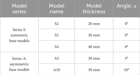
Methods: We had successfully simulated the geometry and progressive evolution of conjugate strike-slip faults in three sets of symmetric models with varying sandpack thicknesses and two sets of asymmetric models with different angles using scaled sandbox model. Three representative phases from all the models were described, and the structural characteristics of the different models were analyzed comparatively.
Results: The results show that well-defined X-shaped conjugate strikeslip faults developed in both the symmetric and asymmetric basement models, they had the same acute angle, and the direction of these angle bisectors was perpendicular to the extension direction. In addition, the development of conjugate strike-slip faults in the asymmetric basement was regionalized compared to the symmetric basement, where the two sets of faults less intersect in the model, and the regionality and asymmetry became more apparent as the degree of basement asymmetry increased.
Discussion: The Mohr space diagrams indicate that there are variations in the characteristics of the faults due to changes in the stress state of the model at different stages. In the asymmetric model, there are differences in the number of two faults developed and the intersection relationship in different regions due to the asymmetry in the distribution of the maximum principal stresses. Furthermore, we proposed two synoptic models, namely, the symmetric conjugate strike-slip fault system (SCSFS) model and the asymmetric conjugate strike-slip fault system (ACSFS) model, for conjugate strike-slip fault systems based on the results of the different models. The models and experimental results were compared with natural examples of the two sets of strike-slip fault systems in the Tabei uplift in China’s Tarim Basin, which exhibit many strong similarities in their structural geometries. The two synoptic models proposed based on the analogue models may provide useful templates for the seismic interpretation and mechanism of different types of conjugate strike-slip fault systems in nature and for inferring the orientation of the maximum principal stress.
1 Introduction
Conjugate strike-slip faults are one of three typical types of faults in the Anderson fault model (Anderson, 1905; 1942) and are given a special definition (Twiss and Moores, 1992; Fossen, 2016) that emphasizes the characteristics of two sets of strike-slip faults with different directions and their interrelationship, which are usually intersected in an X-shape (Figure 1). The mechanics of conjugate strike-slip faults can be explained by pure shear models (sometimes called the Coulomb-Anderson model) (Figure 1) (Aydin and Page, 1984; Sylvester, 1988). The acute angle between the plane of the two faults in a conjugate strike-slip fault is 2θ. θ is the angle between the maximum compressive stress (σ1) direction and a plane of the fault, which is related to the internal friction angle φ (typically 30°–40°) as follows: θ = 45° – φ/2. Thus, the conjugate shear angle is generally 50°–60° (Figure 1).
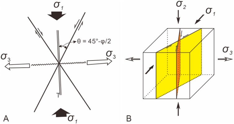
Figure 1. (A) Plan view of mechanisms of pure shear models [after Aydin and Page (1984); Sylvester (1988)]; (B) Three-dimensional stress state of conjugate strike-slip faults in pure shear models. The double parallel line represents the orientation of the extension (T) fractures; and the wavy line represents the orientation of the fold axes. φ is the internal friction angle; σ1 is the maximum principal stress; σ2 is the middle principal stress; and σ3 is the minimum principal stress. The black arrows denote the shortening axis; and the open arrows denote the axis of the lengthening.
Ever since conjugate strike-slip faults were mentioned in Daubrée’s experiments, they have gradually become well-known members of fault systems (Daubrée, 1878; Schwarz and Kilfitt, 2008). The structural characteristics, kinematics, and mechanics of conjugate strike-slip faults have been investigated theoretically (e.g., Anderson, 1942; Aydin and Page, 1984; Sylvester, 1988; Twiss and Moores, 1992; Fossen, 2016; Platt and Passchier, 2016). Examples of conjugate strike-slip faults are found in different tectonic regions on Earth, including collisional orogens (Şengör and Kidd, 1979; Yin et al., 1999; Brookfield and Hashmat, 2001; Morley, 2001; Morley et al., 2001; Cunningham, 2005; Guest et al., 2006; Yin and Taylor, 2011), arc systems (Backé et al., 2006; Escalona and Mann, 2006; Giaconia et al., 2012; Davidson et al., 2020), and cratonic basins (Lin et al., 2015; Deng et al., 2019; Wu et al., 2020). The Tarim Basin is a typical cratonic basin characterized by the development of conjugate strike-slip faults (Figure 2) (Wu et al., 2018; Deng et al., 2019; Wu et al., 2020). In the Tabei uplift in the Tarim Basin, NW China, in addition to the development of a typical X-shaped conjugate strike-slip fault system composed of complementary NNE- and NNW-trending strike-slip faults (the red area in Figure 3), a special strike-slip fault system consisting of nearly NS- and NE-trending strike-slip faults also developed (the yellow area in Figure 3). In this fault system, the NE-trending strike-slip faults are more developed than the nearly NS-trending strike-slip faults, and a few of the faults in these two sets of faults intersect with each other. It is worth noting that a NEE-trending reverse fault developed in the northern part of this fault system, and the amount of shortening on this fault varies from west to east (Lin et al., 2015; Deng et al., 2019; Wu et al., 2020).
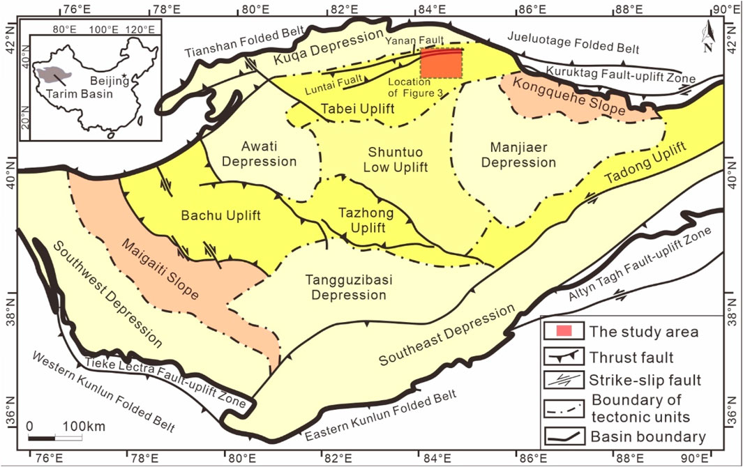
Figure 2. Distribution map of the major tectonic units in the Tarim Basin [modified from Deng et al. (2019)]. The red rectangular area is the location of Figure 3.
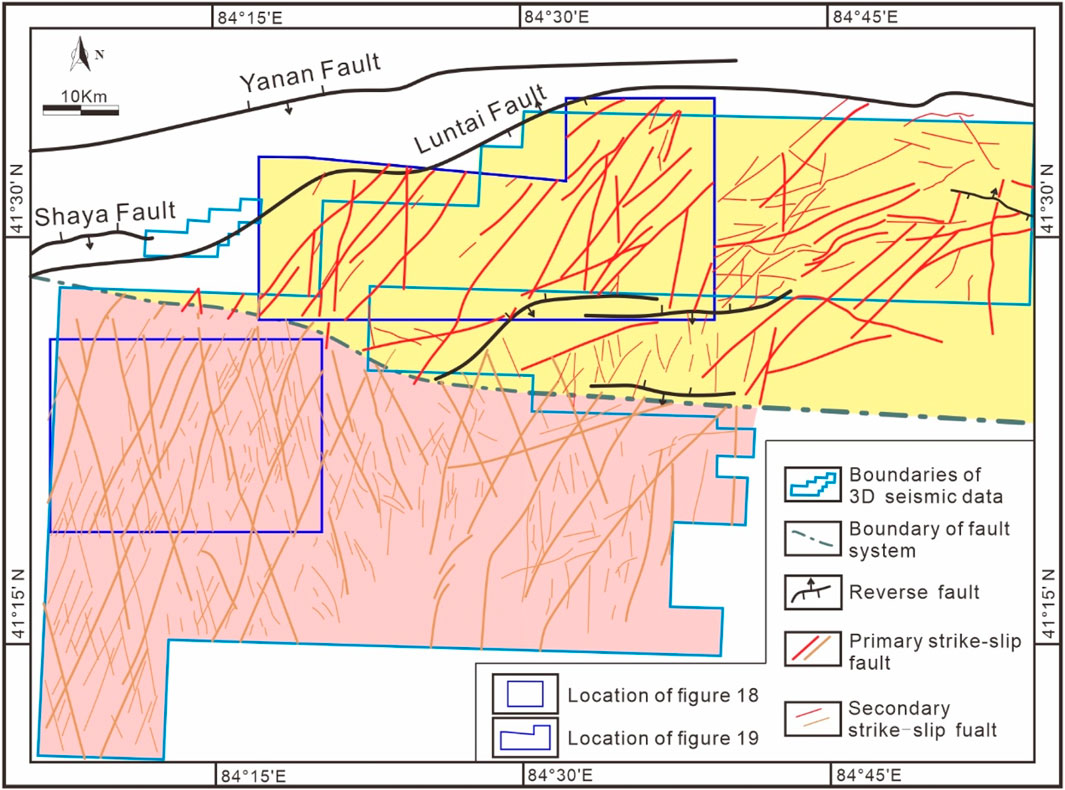
Figure 3. Distribution of the strike-slip faults (the red lines) in the Tabei uplift. The map also shows the basement faults documented by Lin et al. (2015) and Deng et al. (2019). Both the strike-slip faults are projected onto surface T74 (top of Middle Ordovician). The background colours indicate the different fault systems: the southern and northern areas are shown in the red and yellow, respectively. Thick red lines and thin red lines represent primary and secondary strike-slip faults, respectively. The location of Figure 3 is shown in Figure 2. 3D: three-dimensional.
Previous analogue studies of conjugate strike-slip faults have used different materials and set-ups to understand conjugate strike-slip faults. Most of the above-mentioned experiments used clay or plasticine as a modelling material (Cloos, 1955; Hoeppener et al., 1969; Freund, 1970; 1974; An and Sammis, 1996; Schwarz and Kilfitt, 2008; Yin and Taylor, 2011) or designed pre-existing fabrics in analogue models (Schwarz and Kilfitt, 2008; Yin and Taylor, 2011) to simulate the formation and evolution of conjugate strike-slip faults. Recent modelling efforts have started to explore the formation and evolution of X-shaped conjugate strike-slip faults. Bahroudi et al. (2003) used sandbox models to investigate the effects of frictional and ductile detachments on thin-skinned extension and briefly discussed the features of conjugate faults. Zwaan et al. (2019) discussed the development of conjugate strike-slip faults in a systematic comparison of extensional tectonic deformation characteristics under different basement models, involving a foam base, a rubber base, rigid basal plates or a conveyor base system.
However, the clay or plasticine material used in earlier models (Cloos, 1955; Hoeppener et al., 1969; Freund, 1970; 1974; An and Sammis, 1996; Schwarz and Kilfitt, 2008; Yin and Taylor, 2011) cannot be used as precise-scale analogues of brittle deformation in the upper crust (Horsfield, 1977; Naylor et al., 1986; McClay and White, 1995; McClay and Bonora, 2001; Dooley and Schreurs, 2012). In addition, based on the definition of conjugate strike-slip faults (Twiss and Moores, 1992; Fossen, 2016), models with pre-existing structures in the basement (Schwarz and Kilfitt, 2008; Yin and Taylor, 2011) are unconformable with the mechanism of conjugate strike-slip faults, and their experimental results are only slightly similar in geometry to those of conjugate strike-slip faults. Recent modelling has investigated the effects of different basements (Bahroudi et al., 2003; Zwaan et al., 2019; Liu et al., 2024) and different mechanical layers (Liu et al., 2024) on fault development. However, there is rarely any discussion of the formation and evolution of different types of conjugate strike-slip fault systems, particularly the atypical conjugate strike-slip fault systems mentioned above. In addition, these studies do not compare the experimental results with natural examples of different types of conjugate strike-slip fault systems.
In summary, a comprehensive study of the geometries and progressive evolution of two sets of strike-slip faults in different types of conjugate strike-slip fault systems is still lacking (excluding short notes in several previous studies (Anderson, 1942; Aydin and Page, 1984; Sylvester, 1988; Bahroudi et al., 2003; Platt and Passchier, 2016; Zwaan et al., 2019; Liu et al., 2024). In particular, there was a need to compare the results of different types of conjugate strike-slip fault models with natural examples.
Here, we present a systematic series of analogue models consisting of symmetric models with varying sandpack thicknesses and asymmetric models with different angles designed to examine the geometries and progressive evolution of different types of conjugate strike-slip faults. Subsequently, we also analyzed the stress state of the experimental model using the Mohr space diagram to discuss the mechanism of different types of conjugate strike-slip fault systems. Furthermore, two synoptic models for conjugate strike-slip fault systems are developed, and the models and results of these analogue models are compared with natural examples of conjugate strike-slip faults.
2 Materials and methods
Scaled analogue modelling has become a powerful tool used by structural geologists to study the geometries and evolution of faults (Hubbert, 1937; Koyi and Petersen, 1993; McClay and White, 1995; Dooley and McClay, 1997; McClay and Bonora, 2001; Wu et al., 2009; Dooley and Schreurs, 2012; Graveleau et al., 2012; Schellart and Strak, 2016; Zwaan et al., 2019; Zwaan and Schreurs, 2022). In this study, we investigated the geometries and progressive evolution of conjugate strike-slip faults using scaled sandbox modelling, which mainly depended on the materials and experimental setups (McClay and White, 1995; Dooley and McClay, 1997; McClay and Bonora, 2001; Wu et al., 2009; Dooley and Schreurs, 2012; Schellart and Strak, 2016; Zwaan et al., 2019; Zwaan and Schreurs, 2022).
2.1 Material properties and scaling
Qualified materials and model scaling procedures serve to ensure that the experiment properly represents the natural prototype. Dry quartz sand deforms according to Navier-Coulomb failure (Hubbert, 1937; Horsfield, 1977; McClay and White, 1995; McClay and Bonora, 2001; Dooley and Schreurs, 2012), making it an ideal material for simulating the brittle deformation of sediments in the upper crust. It has been widely used in analogue modelling (Horsfield, 1977; Schreurs, 1994; McClay and White, 1995; Dooley and McClay, 1997; McClay and Bonora, 2001; Dooley and Schreurs, 2012; Tong et al., 2014; Reber et al., 2020). In this study, within the deformation rig, a homogeneous sandpack was constructed by mechanically sieving horizontal layers of white, dry quartz sand with a 180–250 μm grain size. Dry quartz sand has a time-independent rheology, so the main concern for scaling purposes is the internal friction angle of the sand (∼40°), which is similar to other models and most intact rocks in the upper crust (35°–40°) (Table 1) (Byerlee, 1978; Jaeger et al., 2009; Dooley and Schreurs, 2012). The cohesion of natural materials in the upper crust is 1.2 × 10⁷ Pa, and that of the sand used in the modelling is 10–100 Pa (Handin, 1969; Twiss and Moores, 1992; Jaeger et al., 2009; Klinkmüller et al., 2016; Zwaan et al., 2019). To ensure dynamic similarity between brittle natural and experimental materials, we calculate the stress ratio Rs, which is a function of gravitational stress and cohesive strength (C) (Hubbert, 1937; Zwaan et al., 2019): Rs = (ρ⋅g⋅h)/C, where ρ, g and h represent the density, gravitational acceleration and thickness respectively. When an intermediate cohesion of ∼8 MPa is applied to upper crustal rocks, we obtain a Rs value of ∼68 for both nature and our experiments, we therefore consider this material in the model to be acceptable. Further details of the modelling materials are presented in Table 1. The thickness of the sandpack in our models varied from 20 to 40 mm. The models described in this article were scaled such that they simulate brittle deformation of a 2–8 km thick sedimentary sequence (Table 1) (McClay, 1990; McClay and White, 1995; Bahroudi et al., 2003; Dooley and Schreurs, 2012).
2.2 Set-up
The experimental apparatus used in this study was similar to the experimental setup used by McClay and White (1995), Model 9 constructed by Bahroudi et al. (2003), and experiment R1 (Zwaan et al., 2019). We present the results of 5 models from two experimental series (Table 2). The width of the two longitudinal walls in the experimental machine was 400 mm; the length between the two longitudinal walls was up to 1,200 mm; and the depth was 200 mm (Figures 4A, B). The initial size of the deformation rig was designed to be 400 × 300 mm. A thin rubber sheet (3 mm) of corresponding size was laid on the baseplate of the model, which was fixed between two sidewalls (Figure 4A) and was designed to represent symmetric and asymmetric basements. The angle, α, between the sides of the rubber base and the extension direction was controlled by the orientation of the rubber base of the model (Figure 4A). The angle was varied systematically in 5° increments, i.e., α = 0° (symmetric basement), α = 5° (asymmetric basement), α = 10° (asymmetric basement) (Figures 4C, D) (Table 2). The rubber was a typical material that transmitted stress to the sandpack through frictional contact with the experimental material (McClay and White, 1995; Bahroudi et al., 2003; Schwarz and Kilfitt, 2008; Zwaan et al., 2019; Zwaan and Schreurs, 2022), and it was pre-stretched to 330 mm to ensure that the rubber was tightly stretched. Thus, the final size of the model was 400 × 330 mm (Figure 4A). Deformation was achieved by moving the mobile sidewall with two motor-driven worm screws (Figure 4B) at a constant displacement rate of 0.17 mm/s. An extension velocity of 0.17 mm/s in our models converts to a velocity of 7.3 cm/y in nature, which was similar to typical natural extension velocities (Liu et al., 2024). All the experiments involved a total extension displacement of 70 mm. The upper surface of each experiment was recorded using time-lapse photography every 1.7 mm (10 s) of displacement. All the images were lightened using the Adobe Photoshop CC 2019 software to make the phenomena in the experimental images more visible. Each model experiment was repeated twice, and good reproducibility was achieved, indicating that our modelling method is robust.
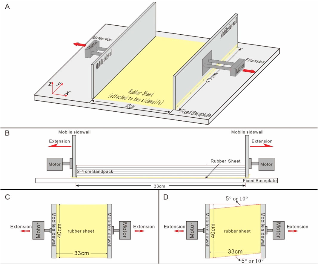
Figure 4. Set-up of the analogue experiments. (A) 3D diagram of the experimental apparatus depicting its various components; (B) diagram of the side view of the deformation rig showing the initial model layering, (C) diagram of the plan view of the deformation rig showing pre-deformation of the symmetric models, and (D) diagram of the plan view of the deformation rig showing pre-deformation of the asymmetric models.
3 Experimental results
We present the results of the analogue model analysis in a series of overview figures (Figures 5–9). These figures present photographs of the top-surface and the interpreted plan views of the key representative deformation phases (d=30 mm, 50 mm, and 70 mm). The scanned plan views of the model surface for both the d=50 mm and 70 mm deformation phases are also presented. First, we discuss the symmetric base models from Series S, and then we discuss the asymmetric base models from Series A. Finally, we compare and analyze the different experiments based on the principle of a single variable. In addition, to better describe the occurrence element of the fault, one direction was designated as the north direction in the plan view (Figures 5–9).
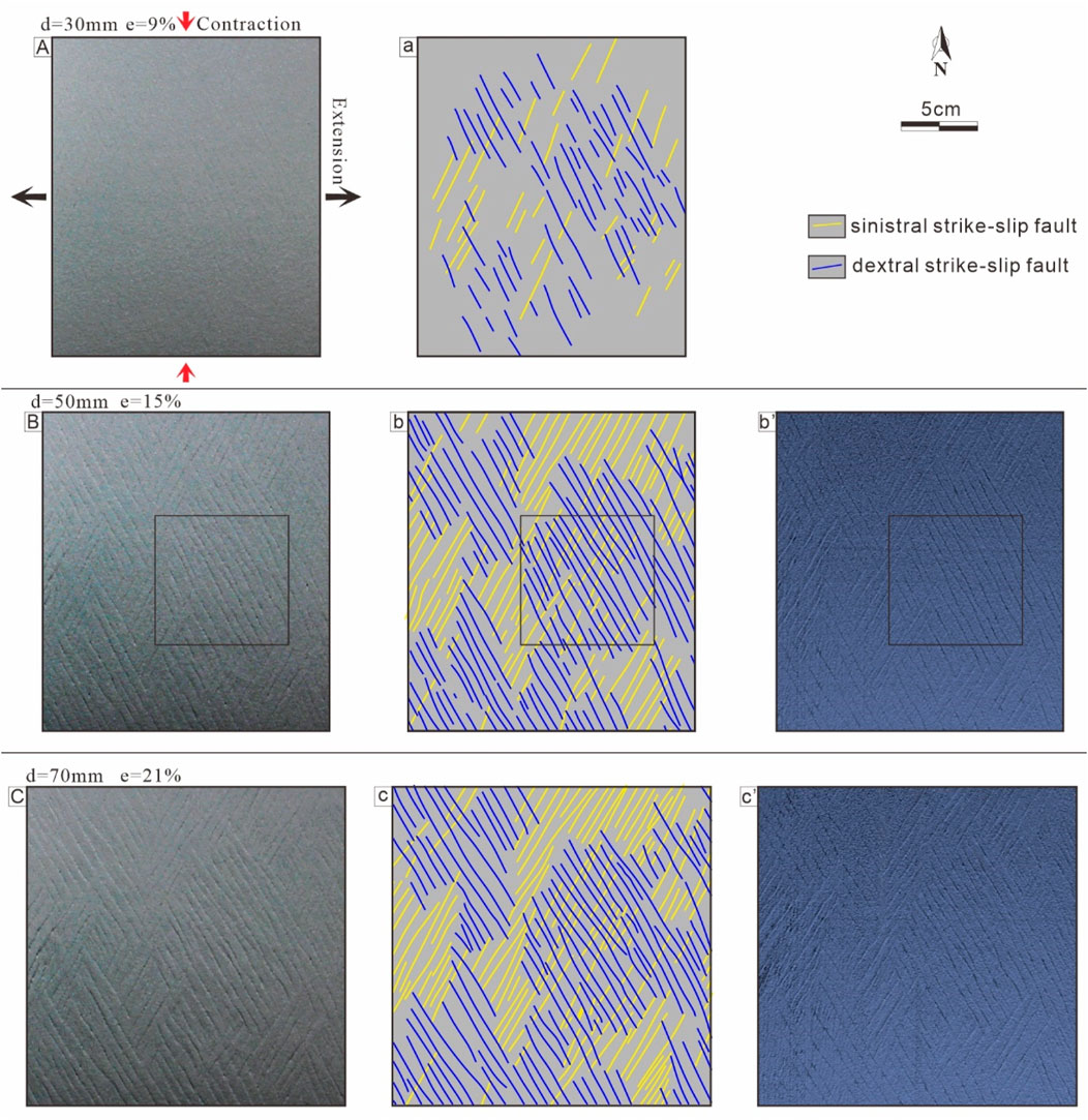
Figure 5. Plan view evolution of Model S2 (D = 20 mm, α = 0°): (A) d = 30 mm, e = 9%; (B) d = 50 mm, e = 15%; (C) d = 70 mm, e = 21%. (a)–(c) present the interpreted plan views of (A–C), respectively. (b’)–(c’) present the scanned plan views of (B, C) surfaces, respectively. The boxed areas [(B), b, and b’] are the site of Figure 18C. d - total displacement, e - extension ratio. The black arrows denote the extension direction; and the red arrows denote the direction of shortening.
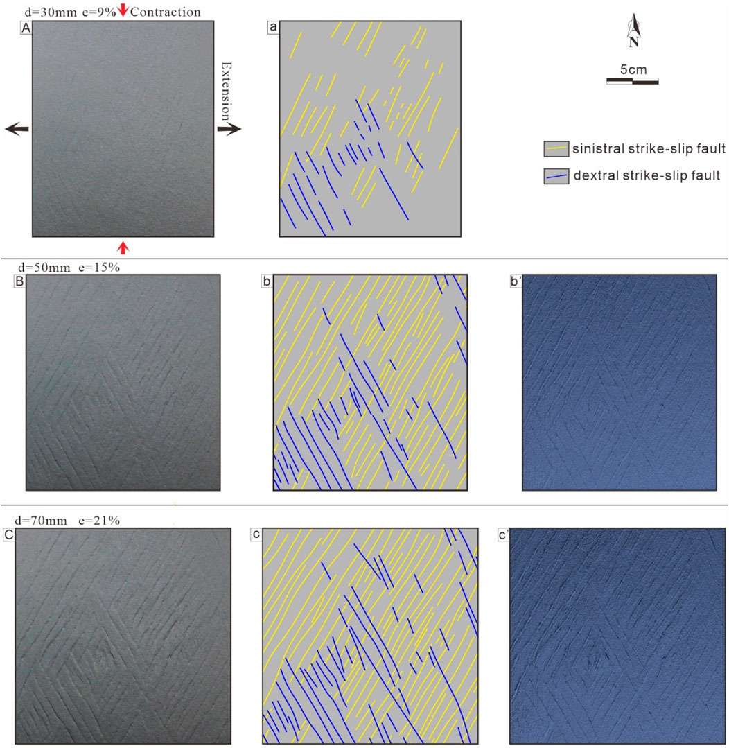
Figure 6. Plan view evolution of Model S3 (D = 30mm, α = 0°): (A) d = 30 mm, e = 9%; (B) d = 50 mm, e = 15%; (C) d = 70 mm, e = 21%. (A–C) present the interpreted plan views of (A–C), respectively. (b’)–(c’) present the scanned plan views of (B, C) surfaces, respectively. d - total displacement, e - extension ratio. The black arrows denote the extension direction; and the red arrows denote the direction of shortening.
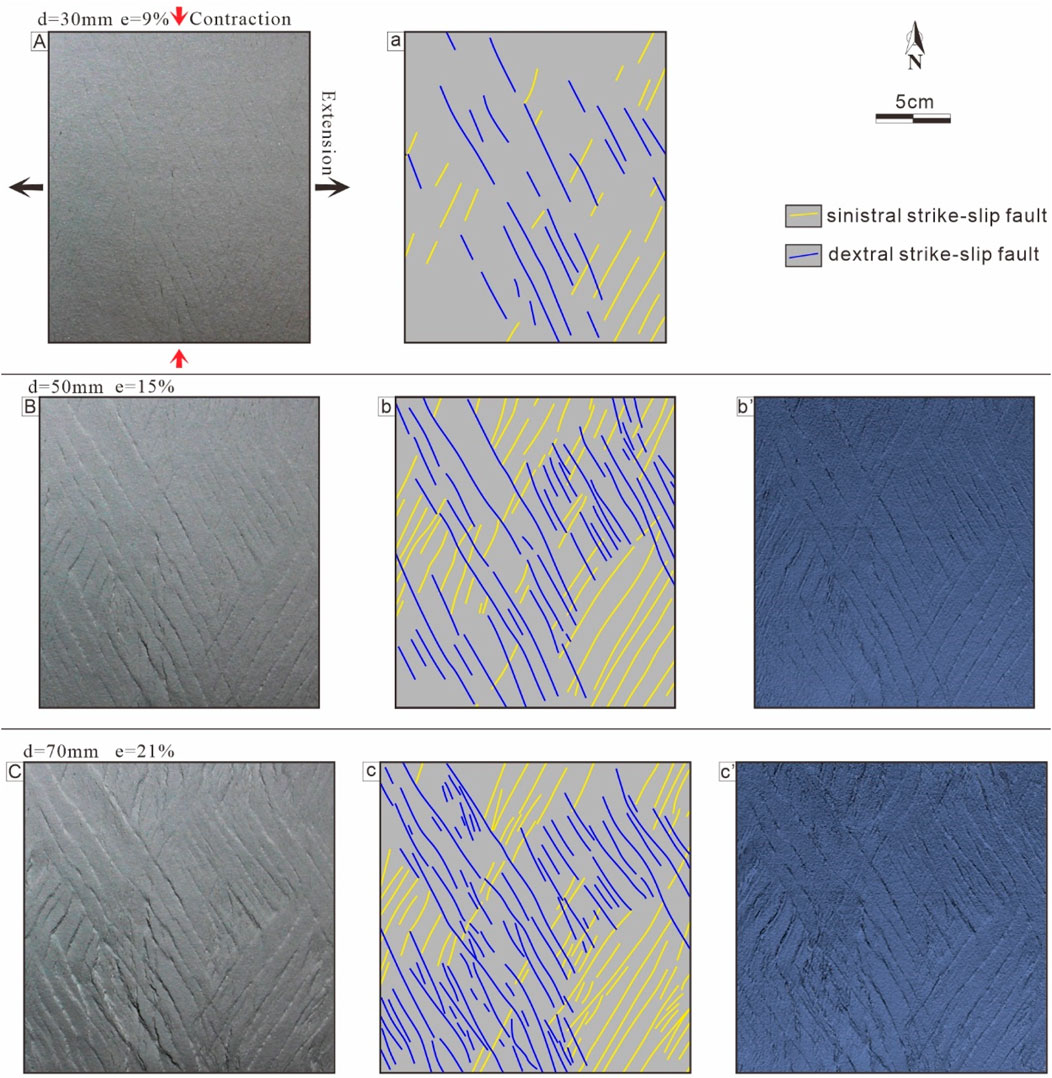
Figure 7. Plan view evolution of Model S4 (D = 40mm, α = 0°): (A) d = 30 mm, e = 9%; (B) d = 50 mm, e = 15%; (C) d = 70 mm, e = 21%. (A–C) present the interpreted plan views of (A–C), respectively. (b’)–(c’) present the scanned plan views of (B, C) surfaces, respectively. d - total displacement, e - extension ratio. The black arrows denote the extension direction; and the red arrows denote the direction of shortening.
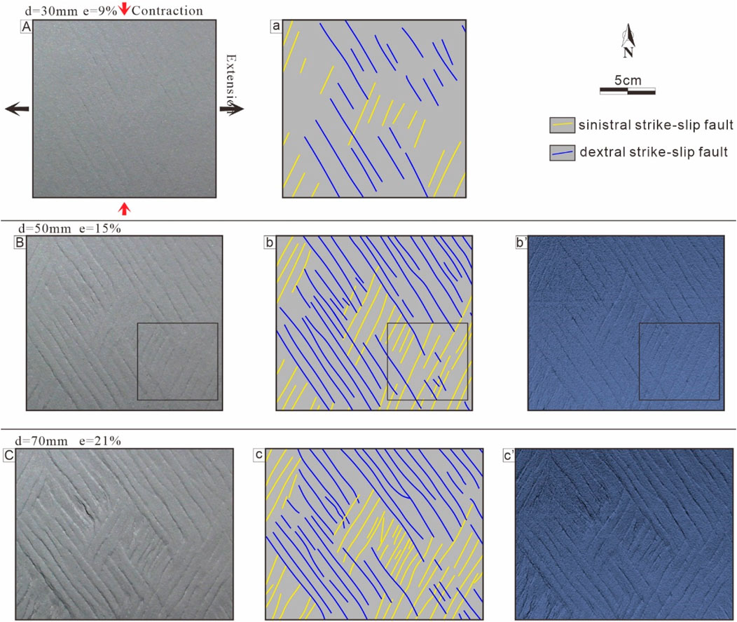
Figure 8. Plan view evolution of Model A5 (D = 30mm, α = 5°): (A) d = 30 mm, e = 9%; (B) d = 50 mm, e = 15%; (C) d = 70 mm, e = 21%. (A–C) present the interpreted plan views of (A–C), respectively. (b’)–(c’) present the scanned plan views of (B, C) surfaces, respectively. The boxed areas [(B), b, and b’] are the site of Figure 19C. d - total displacement, e - extension ratio. The black arrows denote the extension direction; and the red arrows denote the direction of shortening.
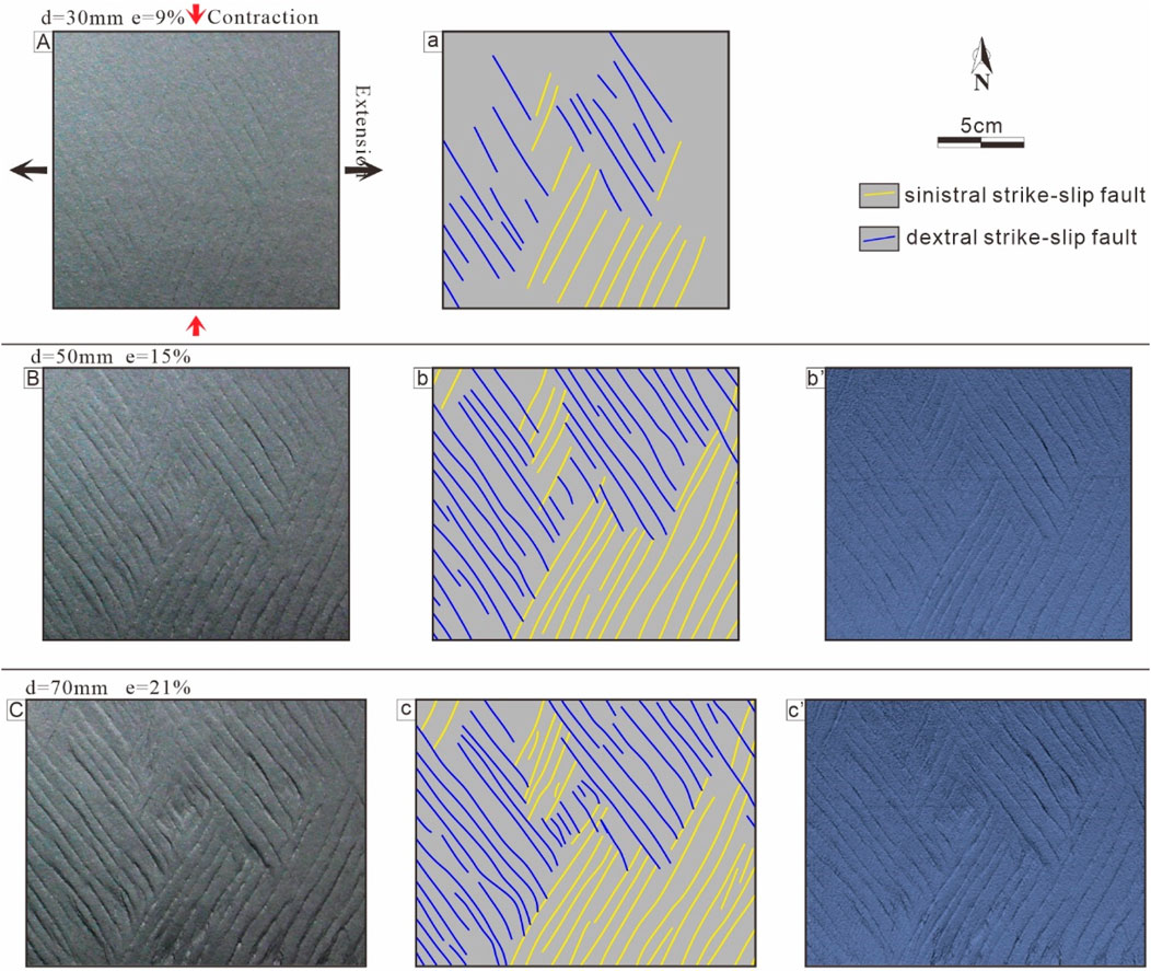
Figure 9. Plan view evolution of Model A10 (D = 30mm, α = 10°): (A) d = 30 mm, e = 9%; (B) d = 50 mm, e = 15%; (C) d = 70 mm, e = 21%. (A–C) present the interpreted plan views of (A–C), respectively. (b’)–(c’) present the scanned plan views of (B, C) surfaces, respectively. d - total displacement, e - extension ratio. The black arrows denote the extension direction; and the red arrows denote the direction of shortening.
3.1 Series S: symmetric base models
The thickness of the sandpack for our Series S models varied systematically from 20 mm to 40 mm (Table 2). Here, to illustrate and compare the geometries and progressive evolution of the conjugate strike-slip faults, we selected representatives of the same phases of the typical areas unaffected by the boundary effect, and the photographs of the representative three selected phases were traced and redrawn (Figures 5–7). In addition, the size and location of the areas selected from Series S are essentially the same.
3.1.1 Plan view evolution: Model S2
In the early phases of deformation (e < 9%, d < 30 mm) in Model S2 (not shown), fault development was not well characterized. Subsequently (e = 9%, d = 30 mm) (Figure 5Aa), the top-view image illustrates the development of conjugate strike-slip faults. They were almost straight in the strike direction, were almost synchronous, were small in scale, and exhibited negligible strike-slip displacement. In this stage (Figure 5Aa), the dextral strike-slip faults (NW-trending faults) were more developed than the sinistral strike-slip faults (NE-trending faults). The X-shaped conjugate strike-slip faults, which consisted of the two sets of intersecting faults, were discernible in the middle of the image, and the acute angle of the conjugate strike-slip faults (2θ) was approximately 49° (Figure 5Aa). With extension of up to e = 15% (d = 50 mm) (Figure 5B–b’), the conjugate strike-slip faults were well-defined, and the two sets of strike-slip faults continued to develop, with a significant increase in the number of sinistral strike-slip faults. The traces of some faults significantly increased in length as a result of the coalescence of individual fault segments and the continued propagation of the faults. In this stage (Figure 5B–b’), the two sets of strike-slip faults were widely developed and generally equal in number at the top of the model, and the fundamental architecture of the conjugate fault system was established (Figure 5B–b’). In the final stage (e = 21%, d = 70 mm) (Figure 5C–c’), the early strike-slip faults continued to propagate and lengthen, and several new small faults simultaneously developed.
3.1.2 Plan view evolution: Model S3
Model S3 (30 mm thick sandpack), displayed a similar evolution to the 20 mm model S2 previously described. The development of conjugate strike-slip faults was not well-defined during the initial phases (e < 9%, d < 30 mm). As the extension increased (e = 9%, d = 30 mm) (Figure 6Aa), two sets of strike-slip faults with different orientations formed almost distributively and simultaneously in the top-view image. Together, they formed typical X-shaped conjugate strike-slip faults with an acute angle of approximately 49° in some areas of the image (Figure 6Aa). In the late phases of deformation (e = 15%, d = 50 mm, e = 21%, d = 70 mm) (Figures 6B–b’, C–c’), the number and length of the faults increased obviously, yet the sinistral strike-slip faults (NE-trending faults) were more developed than the dextral strike-slip faults (NW-trending faults).
3.1.3 Plan view evolution: Model S4
The developmental characteristics of the conjugate strike-slip faults in Model S4, illustrated in the final overhead view, are somewhat similar to those in Models S2 and S3. We observed that two sets of strike-slip faults with different orientations developed almost synchronously in the model after ∼30 mm of extension (e= 9%, d = 30 mm) (Figure 7Aa), which together formed X-shaped conjugate strike-slip faults with an acute angle of approximately 49° in some areas of the image. With continued deformation (e = 15%, d = 50 mm) (Figure 7Bb’), the numbers and lengths of the two sets of strike-slip faults gradually increased. In the late phases (e = 21%, d = 70 mm) (Figure 7Cc’), the early strike-slip faults continued to develop, and several new small faults with the same strike were simultaneously developed in the vicinity of the larger strike-slip faults.
3.2 Series A: asymmetric base models
The Series A models had asymmetric bases with angles of 5° and 10° (Table 2). Here, we analyzed the results for series A with the same regions and phases that were not disturbed by boundary effects, and we further traced and redrew the top-surface photographs (Figures 8, 9).
3.2.1 Plan view evolution: Model A5
In the early phases of deformation (e = 9%, d = 30 mm) (Figure 8Aa), the top view image contained two sets of strike-slip faults with different strikes; they had almost straight strikes, were almost synchronized, and had a negligible strike-slip displacement. In this stage (Figure 8Aa), the two sets of strike-slip faults rarely intersected with each other to form an X-shaped conjugate strike-slip fault, and the acute angle bisectors of these faults were N-S. With further deformation (e = 15%, d = 50 mm) (Figure 8Bb’), the two sets of strike-slip faults continued to develop, significantly increasing in number and length, and some well-defined conjugate strike-slip faults appeared. The trace lengths of some faults increased significantly owing to the coalescence of individual fault segments and the continued propagation of the faults. In addition, an interesting phenomenon during this stage was that the development of the two sets of strike-slip faults was mutually constrained, so one set of faults terminated in the other. In addition, the development of the two sets of strike-slip faults was divided into areas where one set of faults was significantly developed and the other set of faults was less developed. In the final stage (e = 21%, d = 70 mm) (Figure 8Cc’), the early strike-slip faults continued to propagate and lengthen, and some new small faults simultaneously developed.
3.2.2 Plan view evolution: Model A10
Model A10, which had a two-sided 10° asymmetric base, exhibited an evolution similar to that of Model A5 (described previously). As the extension increased to e = 9% (d = 30 mm) (Figure 9Aa), two sets of well-defined strike-slip faults with different orientations were formed almost distributively and simultaneously in the top-view image. However, these two sets of faults did not form a typical X-shaped conjugate strike-slip fault. In the late phases of deformation (e = 15%, d = 50 mm, e = 21%, d = 70 mm) (Figures 9Bb’, Cc’), the number and length of the faults increased notably, several well-defined conjugate strike-slip faults appeared, and the acute angle bisector of the conjugate strike-slip faults was NS. In these stages (Figures 9Bb’, Cc’), mutual limitation of the development between the two sets of faults occurred, making it possible for the development of one set of faults to terminate the other set of faults. In addition, the development of the two sets of strike-slip faults was distinctly regional, i.e., it occurred in areas where one set of faults was notably developed, and the other set was barely developed.
3.3 Comprehensive analysis of experiments
To further investigate the characteristics of the different models, we selected the same phase (e = 15%, d = 50 mm) of each model (Figures 5–9), which was used to represent the fundamental architecture of the conjugate fault system.
3.3.1 Analysis of Models S2–S4
All three models produced well-developed two sets of strike-slip faults, as well as well-defined X-shaped conjugate slip faults (Figure 10). The acute angle of the interpreted plan views conjugate strike-slip faults (2θ) was approximately 40°, and the interpreted plan views direction of the angular bisector of these acute angles was NS, indicating the contraction direction (Figure 10).
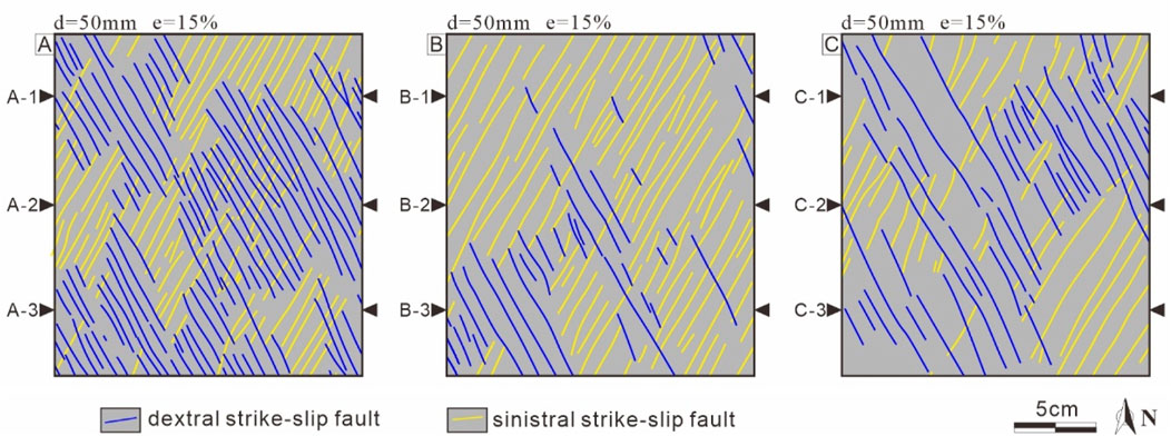
Figure 10. Interpreted plan views of the middle phase (e = 15%, d = 50 mm) in the analogue models: (A) Model S2 (D = 20mm, α = 0°); (B) Model S3 (D = 30mm, α = 0°); and (C) Model S4 (D = 40mm, α = 0°). The locations of the measurement lines (black triangles) illustrated in Figure 11 are shown in (A–C).
In addition to the above-mentioned common features, there were differences in the characteristics of the strike-slip faults formed in Models S2–S4. We compared the fault characteristics in the middle stage in the three models (Figure 10). Here, to further investigate the differential characteristics of the fault from Models S2 to S4, we chose the fault line density (ρL: the number of faults per unit length (number/mm)) and surface density (ρS: the fault length per unit area (mm/mm2)) for analysis. For the line density, we selected the top, middle, and bottom three measurement lines of each model at the same position; then, we statistically analyzed the fault line density of each line (Figures 10, 11A). For the surface density, we measured the lengths of all the strike-slip faults in the models. The statistical analysis revealed that a conjugate set of sinistral and dextral strike-slip faults was developed in all the models, and the line density and surface density of the strike-slip faults in Model S2 were larger than those in the other two models (Figure 11A). Model S4 had the lowest fault density (Figures 11A, B). In addition, the line density of the sinistral and dextral strike-slip faults varied significantly among the different models and in different areas in the same model (Figure 11A).
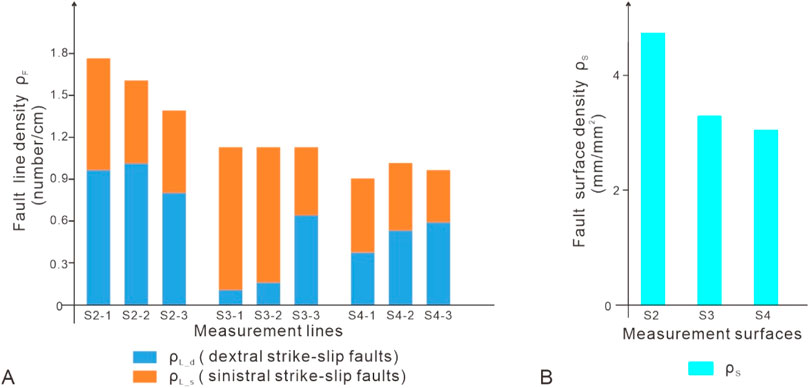
Figure 11. Diagrams of the fault density: (A) stacked map of the NW-trending and NE-trending strike-slip fault line densities along the measurement lines; (B) stacked map of fault surface densities along the interpreted plan views. Figure 10 shows the measurement lines and the interpreted plan views.
3.3.2 Analysis of Models S3, A5, and A10
Here, we selected the same areas in Models S3, A5, and A10. Model S3 contained well-developed X-shaped conjugate strike-slip faults (Figure 12), whereas Models A5 and A10 only contained a few sets of faults that intersected each other to form X-shaped conjugate strike-slip faults (Figures 12B, C). The acute angle of the conjugate fault was about 49° in all the models, and the direction of the angular bisector of the acute angle was NS, indicating the same contraction direction (Figure 12).
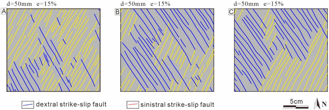
Figure 12. Interpreted plan views of the middle phase (e = 15%, d = 50 mm) in the analogue models: (A) Model S3 (D = 30mm, α = 0°); (B) Model A5 (D = 30mm, α = 5°); and (C) Model A10 (D = 30mm, α = 10°).
Compared with the symmetric base Model S3, the two sets of faults developed in the asymmetric base model were distinctly regionalized; that is, within the region where one set of faults was developed, the other set was barely developed (Figure 12). In addition, the regionalized development of the two sets of strike-slip faults became more distinct as the angle of the base asymmetry increased (Figure 12).
4 Discussion
4.1 Mechanics of experimental models
The reason for the development of the conjugate strike-slip faults in all the experiments described in the previous sections was the contraction of the rubber perpendicular to the extension direction (the Poisson effect) (Figure 13) (Smith and Durney, 1992; Venkat-Ramani and Tikoff, 2002; Zwaan et al., 2019). The deformation of the rubber base was similar to the pure shear mode (Aydin and Page, 1984; Sylvester, 1988), resulting in the development of conjugate strike-slip faults.
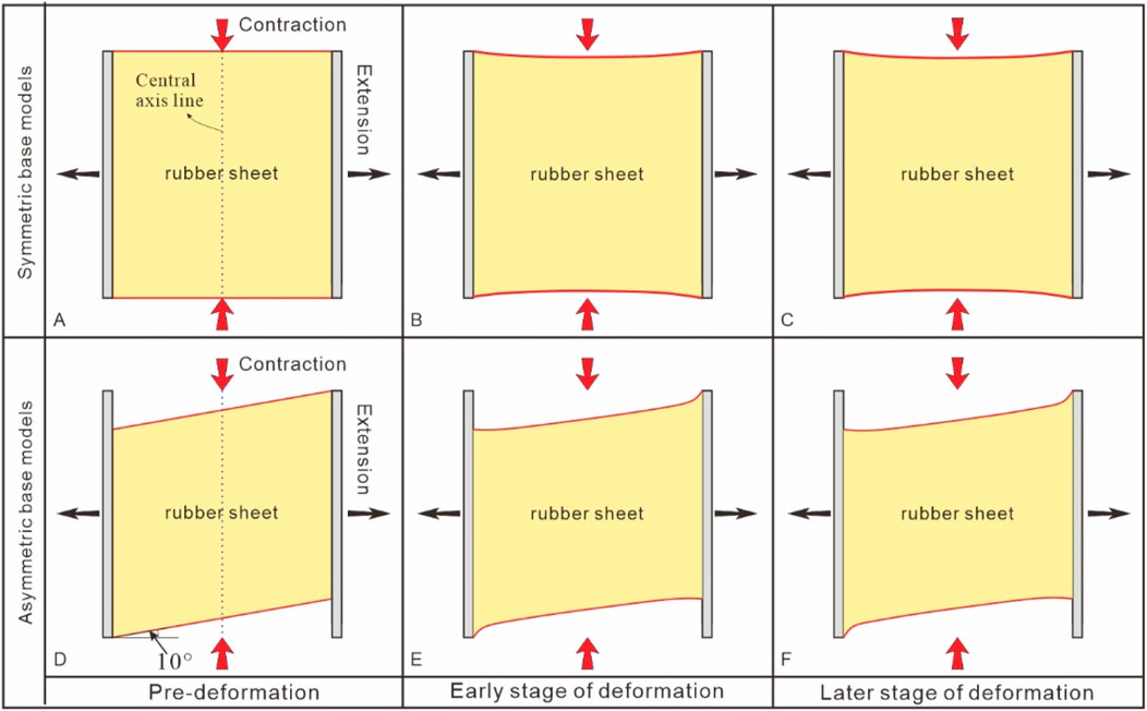
Figure 13. Overview of the evolution patterns of rubber sheet under extension in symmetric base models (A–C) and asymmetric base models (α = 10°) (D–F). (A, D) Rubber sheet pattern in the pre-deformation; (B, E) rubber sheet pattern in the early stage of deformation; and (C, F) rubber sheet pattern in the later stage of deformation. The black arrows denote the extension direction; and the red arrows denote the direction of shortening.
Furthermore, we analyzed the relationship between the extension and contraction perpendicular to the direction of extension during the stretching of the rubber. Here, we chose the central axis line of the rubber for the contraction analysis because the contraction of the different positions on both sides of the rubber was not equal, but both sides had the same deformation tendency (Figure 13A). The relationship between the total extension displacement and total contraction displacement revealed that the rate of increase of the contraction displacement decreased as the stretching displacement increased (Figures 13A–C, 14). Thus, we infer that no visible contraction occurred perpendicular to the extension direction in the later stages of extension, which explains the significant dip-slip displacement of some conjugate strike-slip faults in the later stages.
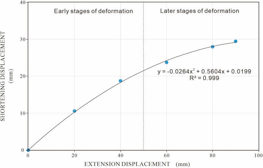
Figure 14. Total extension displacement versus total contraction displacement at the central axis line in symmetric base models.
Next, we used the Mohr space diagram (Tong and Yin, 2011; Tong et al., 2014) to analyze the stress states of our models in the different phases. First, for simplification purposes, we used the three maximum principal stresses to represent the stress state of the model, i.e., the vertical stress (σv), the horizontal stress in the contraction direction (σc), and the horizontal stress in the extension direction (σe).
In the early stages of deformation, the stress state (σc = σ1 > σv = σ2 > σe = σ3) of all the models was the strike-slip tectonic regime of Anderson (Figure 15A). As the extension continued, the contraction rate of the rubber base gradually decreased (Figure 14), σc gradually decreased to less than σv, and the stress state transformed to the extension stress state (σv = σ1 > σc = σ2 > σe =σ3), which caused the early strike-slip faults to reactivate and hence develop dip-slip displacements (Figure 15B). As we have known that the vertical stress (σv = σ2) of the sand body gradually increases as the thickness of the sand layer increases in models. Therefore, we infer that the closer the intermediate principal stress (σ2) is to the maximum principal stress (σ1), the larger the size and density of the fault decreases under the condition that the model is a strike-slip stress state. Additionally, we canned predict that as the thickness of the sandpack increases, the vertical stress (σv = σ1) will become larger than the stress in any horizontal direction in the initial phase of the models (McClay and White, 1995; McClay et al., 2002), and that the stress state would change to a state of extensional stress that would begin to show normal faults in the model.
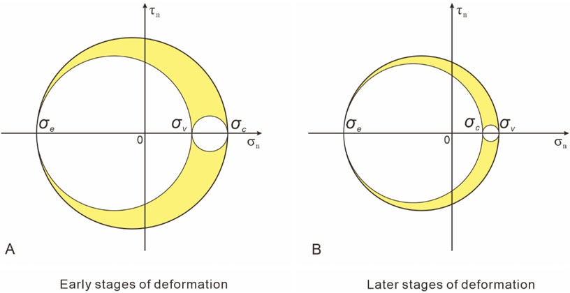
Figure 15. Mohr space diagram showing the stress states at different stages of the analogue model. (A) the stress states in the early stages of deformation; and (B) the stress states in the later stages of deformation. σv is the vertical stress, σc is the horizontal stress in the contraction direction, and σe is the horizontal stress in the extension direction. σn is the normal stress, and τn is the shear stress.
However, compared with the symmetric base model, there was an angle between the boundary of the base of the asymmetric model and the extension direction, which caused the two sides of the rubber basement to contract asymmetrically. During deformation, the contraction rate gradually increased from west to east on the north side of the rubber base, and the opposite process occurred on the south side; therefore, the contraction deformations on both sides were asymmetric (Figures 13D–F). According to the relationship between the extension and shortening of the rubber base (Figure 14), σc was related to the contraction rate, which resulted in an asymmetric distribution of the maximum principal stress (σc) in the model, which was probably the reason the number of faults developed and the intersection relationship between the two sets of faults in the asymmetric model was significantly different, and the regionality and asymmetry became clearer as the magnitude of the asymmetry increased.
4.2 Structural features of conjugate strike-slip faults
Based on the analysis of the symmetric and asymmetric base models, we propose two possible synoptic models to summarize the structural features of the conjugate strike-slip faults observed in the analogue models (Figures 16, 17): a symmetric conjugate strike-slip fault system (SCSFS) and an asymmetric conjugate strike-slip fault system (ACSFS). The SCSFS is defined as a system in which two sets of faults in the conjugate strike-slip fault are well-developed and intersect each other in the strike-slip stress regime (Figure 16). The ACSFS is defined as a system in which one set of faults in the conjugate strike-slip faults is well-developed, the other set of faults is poorly developed, and the two sets of faults less intersect each other within the system (Figure 17). Below, we discuss the representative features of the formation and evolution of these two different conjugate strike-slip fault systems. During the initial formation of conjugate strike-slip faults, there is no measurable dip-slip displacement on the faults (Twiss and Moores, 1992; Fossen, 2016), so it is difficult to observe the profile characteristics of the faults using experimental cross-sections. In addition, we do not have the experimental equipment necessary for 3-D scanning. We refer to Zwaan et al. (2019) for a 3-D analysis of computed tomography (CT) scans of experiments R1 and R5, in which the conjugate strike-slip faults are shown to be sub-vertical and extend to the basement in the profile.
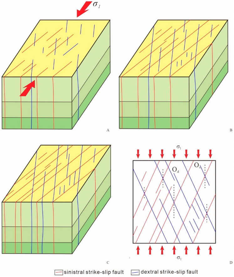
Figure 16. Synoptic model: (A–C) the geometry and progressive evolution of an idealized SCSFS based on the results of the analogue modelling program. (A) the initial phases of the formation; (B) the intermediate phases and (C) the later phases. The schematic diagram in (D) infers the orientation of the maximum principal stress. σ1 is the maximum principal stress, Od is the orientation of the dextral strike-slip faults, Os is the orientation of the sinistral strike-slip faults, and the red arrows indicate the orientation of the maximum principal compressive stress. SCSFS - symmetric conjugate strike-slip fault system.
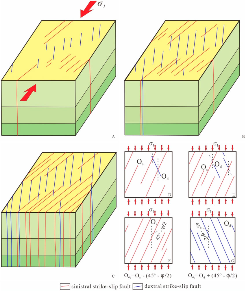
Figure 17. Synoptic model: (A–C) the geometry and progressive evolution of an idealized ACSFS based on the results of the analogue modelling. (D–G) The schematic diagrams infer the orientation of the maximum principal stress. (A) the initial phases of the formation; (B) the intermediate phases and (C) the later phases. σ1 is the maximum principal stress, φ is the internal friction angle, Os is the orientation of the sinistral strike-slip faults, Od is the orientation of the dextral strike-slip faults, Oσ1 is the orientation of the maximum principal stress, and the red arrows indicate the orientation of the maximum principal compressive stress, and its length represents the magnitude of the stress. ACSFS - asymmetric conjugate strike-slip fault system.
4.2.1 Geometries of the SCSFS
The synoptic model of the SCSFS is based on the range of the conjugate strike-slip faults observed in the symmetric base models (Figures 5–7), which exhibits crucial features of the formation and evolution of the SCSFS. (1) In the initial phases of fault development, two well-defined sets of strike-slip faults formed almost synchronously. They had a nearly straight strike, small scale, and no significant amount of strike-slip displacement. In some areas, X-shaped conjugate strike-slip faults were formed via the intersection of the two sets of faults (Figure 16A). (2) In the intermediate phases, the traces of some faults significantly increased in length as a result of the coalescence of individual fault segments and the continued growth of the faults (Figure 16B). The X-shaped conjugate strike-slip faults were well-defined, and the fundamental architecture of the SCSFS was established. (3) In the later phases, the early strike-slip faults continued to develop, and several new small-scale faults with the same strike simultaneously developed in the vicinity of the larger strike-slip faults (Figure 16C).
In the SCSFS, we can directly determine the orientation of the maximum principal stress (Oσ1) from the acute angle bisector of two intersecting conjugate strike-slip faults, which is parallel to the orientation of the maximum principal stress (Figure 16D).
4.2.2 Geometries of the ACSFS
Figure 17 presents a synoptic model of the ACSFS architecture based on the results of the asymmetric base models (Figures 8, 9). This synoptic model has the following key deformations and evolutionary features: (1) During the initial phases of the formation of the ACSFS, well-defined two sets of strike-slip faults with different orientations were formed almost distributivity and simultaneously. Rarely did the two sets of strike-slip faults intersect with each other to form an X-shaped conjugate strike-slip fault (Figure 17A). (2) In the intermediate phases, the number, and length of the well-defined conjugate strike-slip faults increased obviously (Figure 17B). An interesting phenomenon during this stage was the mutual limitation of the development of the two sets of faults, which made it possible for the development of one set of faults to terminate the other set of faults. In addition, the development of the two sets of strike-slip faults was distinctly regional (Figure 17B). (3) In the later phases of the ACSFS formation, the early strike-slip faults continued to propagate and lengthen, and a number of new small faults simultaneously appeared (Figure 17C).
In the ACSFS model, the acute angle bisector of the conjugate strike-slip faults indicates the orientation of the maximum principal stress (Oσ1). In addition, based on the characteristics of the ACSFS model, the orientation of the maximum principal stress can be inferred from the orientations of the sinistral strike-slip faults (Os) and dextral strike-slip faults (Od) (Figure 17E), the internal friction angle (φ) of the rock, and the sense of the shear and the orientation of a set of faults (Figures 17F, G), as well as being based on the acute angle bisector of two intersecting conjugate strike-slip faults (Figure 17D).
The two models can be used as good references for determining the mechanics and the direction of the maximum principal stress of a strike-slip fault system. It should be noted that the key difference between the two fault patterns is the relative numbers of the two sets of strike-slip faults in a strike-slip fault system, but no rigorous distinction has been made between the two patterns in terms of the numerical ratio of the two sets of faults (more than twice the number of faults in one set compared to the other set?). Moreover, it should be noted that the development pattern of faults in nature is very complex, so the conjugate strike-slip fault system is also more variable. The two models proposed in this article are only a reference for the orientation of the maximum principal stress, and more detailed research needs to be conducted in the future.
4.3 Comparison with natural example
The comparison of the experimental results with natural examples is usually based on the geometric similarity, focusing on factors such as the type of example and the symmetry (Schwarz and Kilfitt, 2008). In the following sections, the geometries of the conjugate strike-slip faults in the models are compared with the geometries of natural examples, and strong similarities are apparent. Thus, we can obtain a better understanding of the geometric and kinematic evolution of conjugate strike-slip systems and infer their mechanics.
A natural example of conjugate strike-slip faults is the Tabei uplift in the Tarim Basin, NW China (Wu et al., 2018; Deng et al., 2019; Wu et al., 2020). For the purposes of simplicity, the study area in the Tabei uplift can be divided into a southern area (red area in Figure 3) and a northern area (yellow area in Figure 3) based on the structural characteristics of the primary basement faults (Figure 3).
An X-shaped conjugate strike-slip fault system composed of complementary NNE- and NNW-trending strike-slip faults has been identified between the bottom of the Cambrian (surface T90) and the top of the Lower Ordovician (surface T76) in the southern area of the Tabei uplift (the red area in Figures 3, 18A) (Lin et al., 2015; Deng et al., 2019).
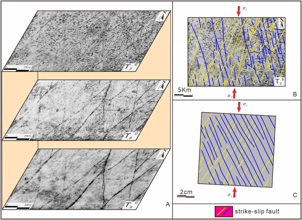
Figure 18. (A) Uninterpreted coherence slices of different seismic reflection surfaces (bottom plot: T90 (bottom of Cambrian), middle plot: T80 (bottom of Ordovician), and top plot: T76 (top of Lower Ordovician)). (B) interpreted coherence slice (T76 (top of Lower Ordovician)) covering the same area (Figure 3). (C) the interpreted plan views of Model S2 (D = 20mm, α = 0°) at d = 50 mm (e = 15%). In (B, C), the NNE-trending faults, NNW-trending faults, and nearly EW-trending faults are shown in blue, yellow, and black, respectively. σ1 is the maximum principal stress, and the red arrows indicate the direction of the maximum principal compressive stress. The location of Figure 18C is shown in Figure 5Bb’.
Two sets of strike-slip faults in the study area are widely developed and are approximately equal in number (Figure 18). Multiple sets of well-defined X-shaped conjugate strike-slip faults have formed via intersection of the two sets of strike-slip faults (Figure 18). In general, the structure of this X-shaped conjugate strike-slip fault system is strikingly similar to the SCSFS model and the fault systems developed in Model S2 (Figures 16, 18). We inferred that the mechanics of the fracture system developed in the southern area of the Tabei uplift was similar to the stress state in the symmetric basement model (Model S2), and that the reason for the slight differences in the density of faults in different regions was the effect of thickness variations.
The orientation of the NNE-trending strike-slip faults is approximately 17°, and that of the NNW-trending strike-slip faults is approximately 337° (Figure 18B). Based on symmetric base models and the SCSFS model, the acute angle between the two sets of faults is approximately 40°, so the maximum principal stress (σ1) orientation can be determined to be approximately 3° (Figure 18B). In addition, the structural features of the strike-slip fault system in the Halahatang area, Tarim Basin, are similar to those of the SCSFS model (Wu et al., 2018; Wu et al., 2020).
Furthermore, nearly NS- and NE-trending strike-slip faults are developed in the top of the Middle Ordovician (surface T80) in the northern area of the Tabei uplift (the yellow area in Figures 3, 19) (Lin et al., 2015; Deng et al., 2019), where NE-trending strike-slip faults are widely developed and north-south trending faults are poorly developed. However, a few sets of well-defined X-shaped conjugate strike-slip faults are also visible in the system due to the intersection of the two sets of faults (Figure 19). The growth of some nearly NS-trending faults is constrained by the NE-trending faults, causing these faults to terminate at the NE-trending faults (Figure 19). The development of faults is regional in this strike-slip fault system. The structure of the conjugate strike-slip fault system in the northern area is similar to the ACSFS model and the fault pattern developed in Model A5 (Figures 17, 19). We infer that the mechanics of the fault system in the northern area of the Tabei uplift is similar to the stress state in the asymmetric basement model (Model A5), and that the development of asymmetrical conjugate strike-slip fault systems in the region is due to the development of boundary faults that result in an asymmetrical distribution of the maximum principal stress (σ1), which results in the development of an asymmetric conjugate strike-slip fault system.
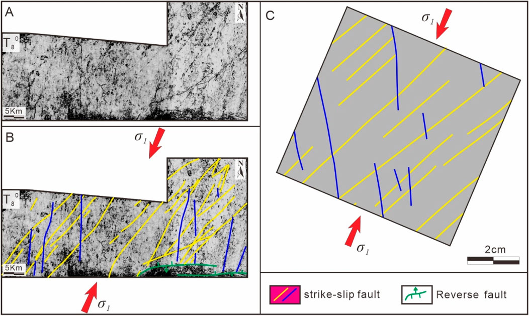
Figure 19. (A) Uninterpreted coherence slices and (B) interpreted coherence slices of seismic reflection surfaces (T80 (bottom of Ordovician)) covering the same area (Figure 3). (C) the interpreted plan views of Model A5 (D = 30mm, α = 5°) at d = 50 mm (e = 15%). In (B, C), the NS-trending faults, NE-trending faults, and thrust faults are shown in blue, yellow, and green, respectively. σ1 is the maximum principal stress, and the red arrows indicate the direction of the maximum principal compressive stress. The location of Figure 19C is shown in Figure 8Bb’.
The nearly NS-trending strike-slip faults are oriented at approximately 3°, and the NE-trending strike-slip faults are oriented at approximately 43°. The acute angle between the two sets of faults is approximately 40°. Based on asymmetric base models and the ACSFS model, we computationally determined that the direction of the maximum principal stress is 23° (Figure 19).
In general, the analogue modelling conducted in this study successfully reproduced the formation and evolution of conjugate strike-slip faults in symmetric and asymmetric base models, which provides an example reference for further studies of conjugate strike-slip faults. However, the complexity of the geological features of the natural examples, i.e., the various pre-existing fabrics and multiple phases of structural evolution, makes the simulation results somewhat different compared to the natural examples. In addition, owing to the limitations of the experimental system, many of the experimental phenomena were not described well, such as the topography in the fault intersection area, the vector fields of the horizontal displacements of the faults, and the internal structures of the faults. In the future, the geometries and evolution of conjugate strike-slip faults can be investigated using different experimental materials, different base materials and shapes, and more sophisticated monitoring devices or stress sensors to identify the distribution of stresses in the asymmetric substrate model and achieve a more systematic study.
5 Conclusion
In this study, we conducted an analogue modelling study of the formation and evolution of conjugate strike-slip faults for symmetric and asymmetric basement conditions. By examining our model results and their mechanics, we reached the following conclusions.
In all of our models, the two sets of strike-slip faults were better developed, and they intersected with each other to form well-defined X-shape conjugate strike-slip faults. The acute angles of the X-shaped conjugate strike-slip faults developed in the symmetric basement model and the asymmetric basement model were the same, and the direction of the bisector of these angles is perpendicular to the direction of extension. The increase in the length of the fault traces is not only related to the growth of the faults but may also be due to the coalescence of individual fault segments.
The development of the two sets of strike-slip faults in the asymmetric basement models was distinctly regionalized compared to that in the symmetric basement models. This was observed within the region, where one set of faults was widely developed, another set was barely developed, and the other two sets of faults seldom intersected each other. There was mutual constraint of the development of the two sets of faults, with some faults being constrained by one another so that one set of faults terminated in the other. In addition, the regional and asymmetric development of the strike-slip faults became more apparent as the degree of basement asymmetry increased.
The Mohr space diagrams reveal that our models were in the strike-slip tectonic regime in the initial stage of the conjugate strike-slip fault development. As the extension continued, the stress state transformed into the extension stress state. Changes in the relative magnitudes of intermediate principal stress (σ2) and maximum principal stress (σ1) due to variations in thickness in the symmetric base models are the main factors controlling the length and density of the fault.
In the asymmetric base models, the rate of contraction perpendicular to the extension direction was asymmetrical, so we infer that the differences in the number of two faults developed and the intersection relationship between them in different regions in the model are affected by asymmetric distribution of maximum principal stresses. Furthermore, we propose two synoptic models, namely, the symmetric conjugate strike-slip fault system (SCSFS) model and the asymmetric conjugate strike-slip fault system (ACSFS) model.
Natural examples of the strike-slip fault systems in the southern and northern areas of the Tabei uplift in the Tarim Basin exhibit structures comparable to those in our models. The two synoptic models developed based on the analogue models may serve as useful templates for identifying the mechanisms of different types of strike-slip fault systems in nature and for determining the orientation of the maximum principal stress.
Data availability statement
The datasets presented in this study can be found in online repositories. The names of the repository/repositories and accession number(s) can be found in the article/supplementary material.
Author contributions
KX: Formal Analysis, Methodology, Software, Visualization, Writing–original draft. HT: Methodology, Supervision, Writing–review and editing.
Funding
The author(s) declare that no financial support was received for the research, authorship, and/or publication of this article.
Acknowledgments
The authors would like to thank the Northwest Oilfield Company (Sinopec) for data access and partial support. We are also grateful to Hao Cui, Guang Li, Qiteng Long, Hongxiang Zhang and Jun Feng for their assistance during the experiments. The editor, Gang Rao, and the reviewers are thanked for the detailed and constructive feedback that helped focusing on the manuscript.
Conflict of interest
The authors declare that the research was conducted in the absence of any commercial or financial relationships that could be construed as a potential conflict of interest.
Publisher’s note
All claims expressed in this article are solely those of the authors and do not necessarily represent those of their affiliated organizations, or those of the publisher, the editors and the reviewers. Any product that may be evaluated in this article, or claim that may be made by its manufacturer, is not guaranteed or endorsed by the publisher.
References
An, L.-J., and Sammis, C. (1996). Development of strike-slip faults: shear experiments in granular materials and clay using a new technique. J. Struct. Geol. 18, 1061–1077. doi:10.1016/0191-8141(96)00012-0
Anderson, E. M. (1942). The dynamics of faulting and dyke formation with applications to Britain. Edinburgh: Oliver & Boyd.
Aydin, A., and Page, B. M. (1984). Diverse pliocene-quaternary tectonics in a transform environment, San Francisco Bay region, California. Geol. Soc. Am. Bull. 95, 1303–1317. doi:10.1130/0016-7606(1984)95<1303:dptiat>2.0.co;2
Backé, G., Dhont, D., and Hervouët, Y. (2006). Spatial and temporal relationships between compression, strike-slip and extension in the Central Venezuelan Andes: clues for Plio-Quaternary tectonic escape. Tectonophysics 425, 25–53. doi:10.1016/j.tecto.2006.06.005
Bahroudi, A., Koyi, H. A., and Talbot, C. J. (2003). Effect of ductile and frictional décollements on style of extension. J. Struct. Geol. 25, 1401–1423. doi:10.1016/S0191-8141(02)00201-8
Brookfield, M. E., and Hashmat, A. (2001). The geology and petroleum potential of the North Afghan platform and adjacent areas (northern Afghanistan, with parts of southern Turkmenistan, Uzbekistan and Tajikistan). Earth-Science Rev. 55, 41–71. doi:10.1016/S0012-8252(01)00036-8
Cloos, E. (1955). Experimental analysis of fracture patterns. Geol. Soc. Am. Bull. 66, 241–256. doi:10.1130/0016-7606(1955)66[241:eaofp]2.0.co;2
Cunningham, D. (2005). Active intracontinental transpressional mountain building in the Mongolian Altai: defining a new class of orogen. Earth Planet. Sci. Lett. 240, 436–444. doi:10.1016/j.epsl.2005.09.013
Daubrée, G. A. (1878). Recherches expérimentales sur les cassures qui traversent l’écorce terrestre, particulièrement celles qui sont connues sous les noms de joints et de failles. Acad. Sci. (Paris) Comptes Rendus 86 (77–83), 283–289.
Davidson, S. R., Barnes, P. M., Pettinga, J. R., Nicol, A., Mountjoy, J. J., and Henrys, S. A. (2020). Conjugate strike-slip faulting across a subduction front driven by incipient seamount subduction. Geology 48, 493–498. doi:10.1130/G47154.1
Deng, S., Li, H. L., Zhang, Z. P., Zhang, J. B., and Yang, X. (2019). Structural characterization of intracratonic strike-slip faults in the central Tarim Basin. Aapg Bull. 103, 109–137. doi:10.1306/06071817354
Dooley, T., and McClay, K. (1997). Analog modeling of pull-apart basins. AAPG Bull. 81, 1804–1826. doi:10.1306/3b05c636-172a-11d7-8645000102c1865d
Dooley, T. P., and Schreurs, G. (2012). Analogue modelling of intraplate strike-slip tectonics: a review and new experimental results. Tectonophysics 574–575, 1–71. doi:10.1016/j.tecto.2012.05.030
Escalona, A., and Mann, P. (2006). An overview of the petroleum system of Maracaibo Basin. AAPG Bull. 90, 657–678. doi:10.1306/10140505038
Freund, R. (1970). Rotation of strike slip faults in Sistan, southeast Iran. J. Geol. 78, 188–200. doi:10.1086/627500
Freund, R. (1974). Kinematics of transform and transcurrent faults. Tectonophysics 21, 93–134. doi:10.1016/0040-1951(74)90064-X
Giaconia, F., Booth-Rea, G., Martínez-Martínez, J., Azañón, J., and Pérez-Peña, J. (2012). Geomorphic analysis of the Sierra Cabrera, an active pop-up in the constrictional domain of conjugate strike-slip faults: the Palomares and Polopos fault zones (eastern Betics, SE Spain). Tectonophysics 580, 27–42. doi:10.1016/j.tecto.2012.08.028
Graveleau, F., Malavieille, J., and Dominguez, S. (2012). Experimental modelling of orogenic wedges: a review. Tectonophysics 538–540, 1–66. doi:10.1016/j.tecto.2012.01.027
Guest, B., Axen, G. J., Lam, P. S., and Hassanzadeh, J. (2006). Late Cenozoic shortening in the west-central Alborz Mountains, northern Iran, by combined conjugate strike-slip and thin-skinned deformation. Geosphere 2, 35–52. doi:10.1130/GES00019.1
Handin, J. (1969). On the Coulomb-Mohr failure criterion. J. Geophys. Res. 74, 5343–5348. doi:10.1029/JB074i022p05343
Hoeppener, R., Kalthoff, E., and Schrader, P. (1969). Zur physikalischen Tektonik Bruchbildung bei verschiedenen affinen Deformationen im Experiment. Geol. Rundsch. 59, 179–193. doi:10.1007/BF01824950
Horsfield, W. T. (1977). An experimental approach to basement-controlled faulting. Geol. Mijnb. 56, 363–370.
Hubbert, M. K. (1937). Theory of scale models as applied to the study of geologic structures. Bull. Geol. Soc. Am. 48, 1459–1520. doi:10.1130/GSAB-48-1459
Jaeger, J. C., Cook, N. G., and Zimmerman, R. (2009). Fundamentals of rock mechanics. John Wiley and Sons.
Klinkmüller, M., Schreurs, G., Rosenau, M., and Kemnitz, H. (2016). Properties of granular analogue model materials: a community wide survey. Tectonophysics 684, 23–38. doi:10.1016/j.tecto.2016.01.017
Koyi, H., and Petersen, K. (1993). Influence of basement faults on the development of salt structures in the Danish Basin. Mar. Petrol Geol. 10, 82–94. doi:10.1016/0264-8172(93)90015-K
Lin, B., Zhang, X., Xu, X. C., Yuan, J. Y., Neng, Y., and Zhu, J. W. (2015). Features and effects of basement faults on deposition in the Tarim Basin. Earth-Sci Rev. 145, 43–55. doi:10.1016/j.earscirev.2015.02.008
Liu, J., Rosenau, M., Brune, S., Kosari, E., Rudolf, M., and Oncken, O. (2024). Fault networks in triaxial tectonic settings: analog modeling of distributed continental extension with lateral shortening. Tectonics 43, e2023TC008127. doi:10.1029/2023TC008127
McClay, K. (1990). Extensional fault systems in sedimentary basins: a review of analogue model studies. Mar. Pet. Geol. 7, 206–233. doi:10.1016/0264-8172(90)90001-W
McClay, K., and Bonora, M. (2001). Analog models of restraining stepovers in strike-slip fault systems. AAPG Bull. 85, 233–260. doi:10.1306/8626c7ad-173b-11d7-8645000102c1865d
McClay, K. R., Dooley, T., Whitehouse, P., and Mills, M. (2002). 4-D evolution of rift systems: insights from scaled physical models. AAPG Bull. 86, 935–959. doi:10.1306/61eedbf2-173e-11d7-8645000102c1865d
McClay, K. R., and White, M. J. (1995). Analogue modelling of orthogonal and oblique rifting. Mar. Pet. Geol. 12, 137–151. doi:10.1016/0264-8172(95)92835-K
Morley, C. (2001). Combined escape tectonics and subduction rollback–back arc extension: a model for the evolution of Tertiary rift basins in Thailand, Malaysia and Laos. J. Geol. Soc. 158, 461–474. doi:10.1144/jgs.158.3.461
Morley, C., Woganan, N., Sankumarn, N., Hoon, T., Alief, A., and Simmons, M. (2001). Late Oligocene–Recent stress evolution in rift basins of northern and central Thailand: implications for escape tectonics. Tectonophysics 334, 115–150. doi:10.1016/S0040-1951(00)00300-0
Naylor, M., Mandl, G. t., and Supesteijn, C. (1986). Fault geometries in basement-induced wrench faulting under different initial stress states. J. Struct. Geol. 8, 737–752. doi:10.1016/0191-8141(86)90022-2
Platt, J. P., and Passchier, C. W. (2016). Zipper junctions: a new approach to the intersections of conjugate strike-slip faults. Geology 44, 795–798. doi:10.1130/G38058.1
Reber, J. E., Cooke, M. L., and Dooley, T. P. (2020). What model material to use? A Review on rock analogs for structural geology and tectonics. Earth Sci. Rev. 202, 103107. doi:10.1016/j.earscirev.2020.103107
Schellart, W. P., and Strak, V. (2016). A review of analogue modelling of geodynamic processes: approaches, scaling, materials and quantification, with an application to subduction experiments. J. Geodyn. 100, 7–32. doi:10.1016/j.jog.2016.03.009
Schreurs, G. (1994). Experiments on strike-slip faulting and block rotation. Geology 22, 567–570. doi:10.1130/0091-7613(1994)022<0567:eossfa>2.3.co;2
Schwarz, H.-U., and Kilfitt, F.-W. (2008). Confluence and intersection of interacting conjugate faults: a new concept based on analogue experiments. J. Struct. Geol. 30, 1126–1137. doi:10.1016/j.jsg.2008.05.005
Şengör, A., and Kidd, W. (1979). Post-collisional tectonics of the Turkish-Iranian plateau and a comparison with Tibet. Tectonophysics 55, 361–376. doi:10.1016/0040-1951(79)90184-7
Smith, J. V., and Durney, D. W. (1992). Experimental formation of brittle structural assemblages in oblique divergence. Tectonophysics 216, 235–253. doi:10.1016/0040-1951(92)90399-Q
Sylvester, A. G. (1988). Strike-slip faults. Geol. Soc. Am. Bull. 100, 1666–1703. doi:10.1130/0016-7606(1988)100<1666:ssf>2.3.co;2
Tong, H., Koyi, H., Huang, S., and Haitao, Z. (2014). The effect of multiple pre-existing weaknesses on formation and evolution of faults in extended sandbox models. Tectonophysics 626, 197–212. doi:10.1016/j.tecto.2014.04.046
Tong, H., and Yin, A. (2011). Reactivation tendency analysis: a theory for predicting the temporal evolution of preexisting weakness under uniform stress state. Tectonophysics 503, 195–200. doi:10.1016/j.tecto.2011.02.012
Venkat-Ramani, M., and Tikoff, B. (2002). Physical models of transtensional folding. Geology 30, 523–526. doi:10.1130/0091-7613(2002)030<0523:pmotf>2.0.co;2
Wu, G., Yuan, Y., Huang, S., Vandyk, T. M., Xiao, Y., Cai, Q., et al. (2018). The dihedral angle and intersection processes of a conjugate strike-slip fault system in the Tarim Basin, NW China. Acta Geol. Sinica-English Ed. 92, 74–88. doi:10.1111/1755-6724.13495
Wu, G. H., Kim, Y. S., Su, Z., Yang, P. F., Ma, D. B., and Zheng, D. M. (2020). Segment interaction and linkage evolution in a conjugate strike-slip fault system from the Tarim Basin, NW China. Mar. Petrol Geol. 112, 104054. doi:10.1016/j.marpetgeo.2019.104054
Wu, J. E., McClay, K., Whitehouse, P., and Dooley, T. (2009). 4D analogue modelling of transtensional pull-apart basins. Mar. Pet. Geol. 26, 1608–1623. doi:10.1016/j.marpetgeo.2008.06.007
Yin, A., Kapp, P. A., Murphy, M. A., Manning, C. E., Mark Harrison, T., Grove, M., et al. (1999). Significant late Neogene east-west extension in northern Tibet. Geology 27, 787–790. doi:10.1130/0091-7613(1999)027<0787:slnewe>2.3.co;2
Yin, A., and Taylor, M. H. (2011). Mechanics of V-shaped conjugate strike-slip faults and the corresponding continuum mode of continental deformation. Geol. Soc. Am. Bull. 123, 1798–1821. doi:10.1130/B30159.1
Zwaan, F., and Schreurs, G. (2022). “Analogue modelling of continental rifting: an overview,” in Continental rifted margins I (ISTE-Wiley). Available at: https://www.researchgate.net/publication/349536310_Analogue_modelling_of_continental_rifting_an_overview.
Keywords: conjugate strike-slip faults, analogue modelling, strike-slip fault systems, geometries and evolution of faults, mechanism, Tarim Basin
Citation: Xiao K and Tong H (2024) Analogue modelling of conjugate strike-slip faults. Front. Earth Sci. 12:1493537. doi: 10.3389/feart.2024.1493537
Received: 09 September 2024; Accepted: 23 October 2024;
Published: 05 November 2024.
Edited by:
Gang Rao, Southwest Petroleum University, ChinaCopyright © 2024 Xiao and Tong. This is an open-access article distributed under the terms of the Creative Commons Attribution License (CC BY). The use, distribution or reproduction in other forums is permitted, provided the original author(s) and the copyright owner(s) are credited and that the original publication in this journal is cited, in accordance with accepted academic practice. No use, distribution or reproduction is permitted which does not comply with these terms.
*Correspondence: Hengmao Tong, dG9uZ2htQGN1cC5lZHUuY24=
 Kunze Xiao
 Hengmao Tong1,2*
