- 1Suzhou New District Testing Corporation, Suzhou, China
- 2College of Harbour, Coastal and Offshore Engineering, Hohai University, Nanjing, China
Geosynthetic-reinforced pile-supported embankments have seen widespread adoption worldwide in recent years due to their cost-effectiveness and construction efficiency. In this system, the conventional pile cap is replaced by the geogrid-reinforced soil platform (GRSP), which enhances horizontal load transfer to stabilize the embankment. This study investigates the influences of GRSP on the behavior of pile-supported embankments through field testing and numerical computation. The measured results of field testing indicate that a well-compacted GRSP reduces the lateral displacement of the embankment and changes the development of pressures acting on pile and soil. Numerical analysis demonstrates that both soil arching and tensioned membrane effects effectively transfer loads from the soil to the piles, with the tensioned membrane effect typically being more prominent. The characteristics of the GRSP have a significant impact on both effects, with elastic modulus, tensile stiffness, and friction angle being the three most crucial parameters for reducing embankment settlement.
1 Introduction
A large number of highway embankments are constructed on soft soil, and the geosynthetic-reinforced pile-supported embankments have been increasingly adopted all over the world in the recent years (Liu et al., 2007; 2015; Xing et al., 2014; Esmaeili et al., 2018; Wu et al., 2022; Du et al., 2024) owing to their high cost effectiveness and construction efficiency. In this system, piles (i.e., concrete pile, deep mix column, and stone pile) reinforce the soft soil vertically and are important to impart the loads from the embankment to deeper firm soil (Pham et al., 2004; Stewart et al., 2004; Huang et al., 2009). The geosynthetic-reinforced soil platform (GRSP) enhances horizontal load transfer to stabilize the embankment, and the conventional pile cap is replaced by GRSP, allowing the load between piles to be partially transferred to the pile head (Han J. and Gabr M. A., 2002; Briançon and Simon, 2012; Rowe and Liu, 2015). The GRSP consists of a single or multiple geosynthetic layers (such as geogrid) and soil, with the cohesionless soil being commonly used in practice due to drainage and consolidation of foundation soil under embankment loading. Since the piles bear the majority of the embankment load, the stress on the foundation soil is substantially reduced, leading to a decrease in both vertical and lateral displacements of the embankment. Consequently, this approach allows for the construction of higher embankments on soft soil. The behavior of geosynthetic-reinforced pile-supported embankment was investigated by model experiments (Blanc et al., 2013; Okyay et al., 2014; Rui et al., 2019; Shen et al., 2020), full-scale field tests (Briançon and Simon, 2012; Zhou et al., 2016; van Eekelen et al., 2020; Terqueux et al., 2023), and numerical simulations (Huang and Han, 2010; Borges and Marques, 2011; Rowe and Liu, 2015; Badakhshan et al., 2020; Ghosh et al., 2021; Khosrojerdi et al., 2018). The performance of load transfer from soft soil to piles has been widely acknowledged as the soil arching effect in embankments (Terzaghi, 1943). Apart from the model proposed by Terzaghi (1936), various methods have been introduced to model the soil arching effect (Xu et al., 2018; Yan et al., 2022; Zhang et al., 2022). However, these models generally ignored the influence of the GRSP and the supporting effect of the foundation soil between piles. In addition to the soil arching effect, the tensioned membrane or stiffened platform effect of the GRSP and the stiffness difference between the pile and soil in foundation are load transfer mechanisms (Han J. and Gabr M. A., 2002). Based on the load transfer mechanisms revealed by field or laboratory testing, many design methods have been proposed, but some of them yield quite different results, especially in the tension force of geosynthetics in the GRSP and the stress reduction ratio (Stewart and Filz, 2005; Chen et al., 2010; Rowe and Liu, 2015).
Several studies have addressed the GRSP, primarily focusing on the role of geosynthetics within the system. Analyses have examined how the stiffness of geosynthetics affects the performance of pile-supported embankments, revealing that geosynthetic properties within the GRSP can significantly influence embankment behavior (e.g., settlement and soil arching) and foundation performance (e.g., load transfer efficiency from the soil to pile and differential settlement between the pile and soil) (Han and Gabr, 2002; Huang and Han, 2010).The distribution of tensile force and strain of geosynthetics was obtained via numerical computation and field testing, revealing that the maximum strain and tensile force occur at the edge of pile heads after the completion of the embankment construction (Han J. and Gabr M. A., 2002; Liu et al., 2007; Huang et al., 2009). Furthermore, the effects of multiple layers of geosynthetic reinforcement on the performance of the pile-supported embankment were discussed via field testing and numerical analysis (Briançon and Simon, 2012; Rowe and Liu, 2015). In addition to the effect of geosynthetics in GRSP, the soil in GRSP also influences the load mechanism. As a result of the penetration of the pile head into the GRSP soil (i.e., gravel), the GRSP soil partially moves to the soil surface surrounding the pile, ensuring that the upper loads act on the foundation soil continuously. The contact surface force between geosynthetics and soil in GRSP is influenced by the tensile force in geosynthetics. In summary, the characteristics of the GRSP have significant influences on the load transfer mechanism of the embankment and foundation.
The objective of this study is to report the influences of GRSP on the performance of the pile-supported embankment, and the effect of the compaction of GRSP materials is studied by comparative field testing. Moreover, based on field testing, parametric studies of GRSP materials, including both soil and geogrid, are conducted via the finite-element analysis. The performances of the pile-supported embankment investigated using the numerical analysis include the stress concentration ratio of pile to soil, soil arching effect, tensioned membrane effect, differential settlement of pile and soil, settlement of the embankment surface, and height of the plane of equal settlement in the embankment and its settlement.
2 Full-scale field test
2.1 Site conditions
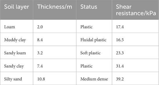
The site is located in a suburb of Jiangsu province, China. The soil profile is as follows: there is a 2.0-m-thick loam overlying an 8.4-m-thick deposit of fluidal plastic muddy clay; this deposit overlies soft, plastic, sandy loam of approximately 3.2 m thick. A sandy clay layer of approximately 7.4 m thick lies beneath the soft sandy loam, followed by a deeper layer of medium-density silty sand of approximately 10.8 m thick. The ground water level was 1.2 m high. The soil properties are listed in Table 1.
2.2 Geogrid-reinforced pile-supported highway embankment
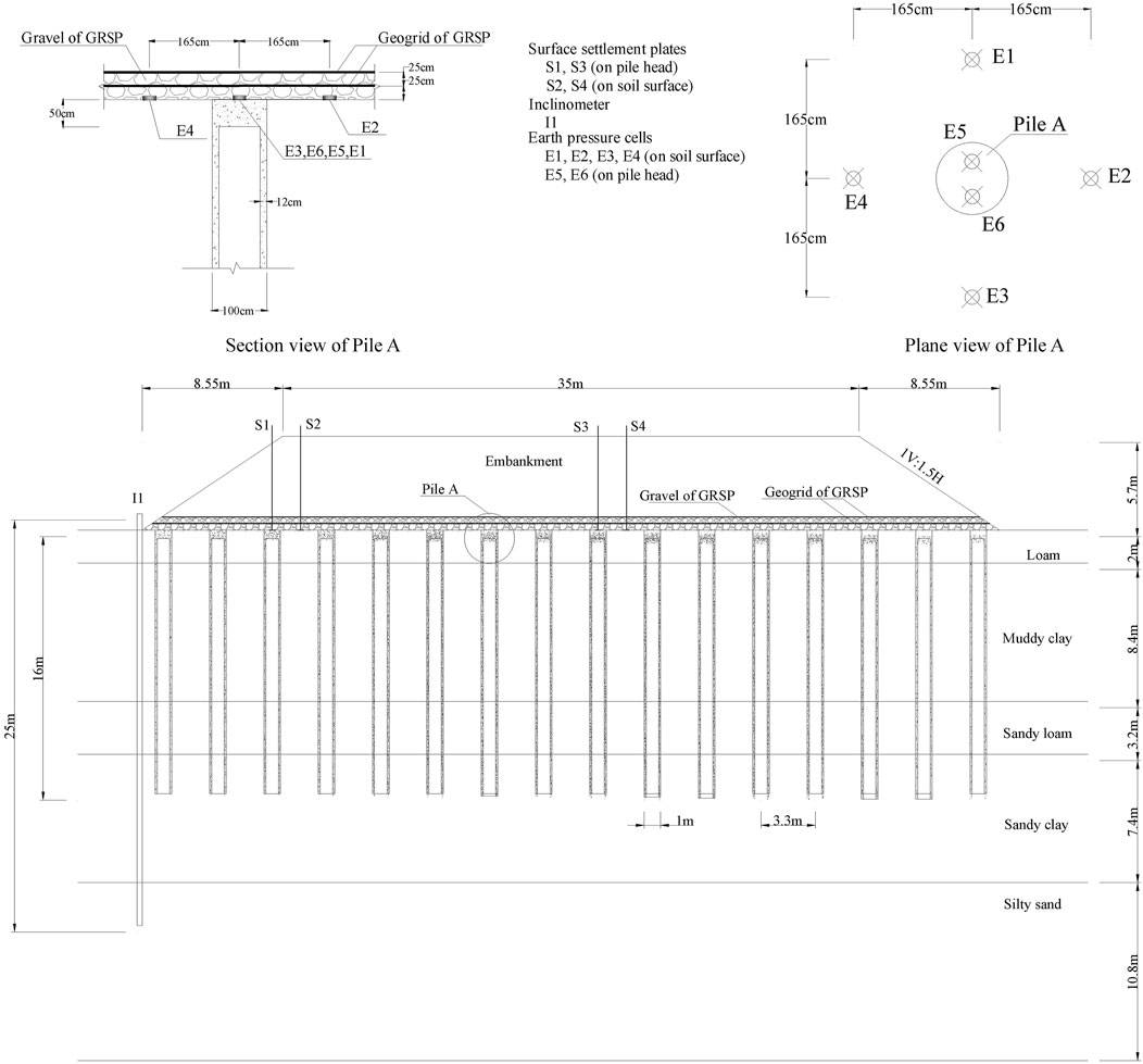
The highway embankment is 5.7 m high and 249 m long with a crown width of 35 m. The side slope is 1V: 1.5H. The filling material mainly consists of pulverized fuel ash and clay with the cohesion of 10 kPa, the angle of friction of 26°, and the average unit weight of 18.5 kN/m3. The cross-sectional view of the testing embankment and the locations of instruments are illustrated in Figure 1.
The embankment is supported by Cast-in situ concrete large-diameter pipe (PCC) pile (Liu et al., 2007). The minimum compressive strength of the concrete is 15 MPa. The pipe piles are 16 m in length, the outer diameter of each pile is 1.0 m, and the thickness of the concrete annulus is 120 mm. The pipe piles are arranged in a square pattern at a spacing of approximately three times the pile diameter (3.3 m) from the center to the center of the adjacent piles. The replacement ratio, defined as the percent coverage of the pile annular area over the total foundation area, is 3.1%. A 0.5-m-thick gravel layer is placed on the top of piles, in which two layers of a biaxial polypropylene geogrid are sandwiched. One layer of the geogrid is placed in the middle of the gravel layer, and the other is placed on the top of the gravel layer. The gravel and geogrid form the composite-reinforced bearing layer between the embankment and pile-reinforced foundation, and the composite-reinforced bearing layer is named GRSP, which is shown in Figure 1. The tensile strength in the longitudinal and latitudinal directions of the geogrid is 90 kN/m, and the natural dry density and the maximum dry density of platform gravel are 1.43 kN/m3 and 1.87 kN/m3, respectively. The details of the geogrid-reinforced platform construction are as follows:
First,, a 0.25-m layer of gravel is placed on top of the piles for platform construction, followed by compaction. Next, the first layer of the geogrid is installed. A second 0.25-m layer of gravel is then placed using two different methods for placement: i) spreading and compacting the gravel from the platform center toward both sides using a 4-ton vibratory compactor to achieve a compaction degree of over 90% and ii) placing the gravel from one side to the other without compaction. Finally, the second geogrid layer is installed atop the gravel. These two construction methods for the geogrid-reinforced platform lead to different gravel densities and interaction forces between the geogrid and gravel before embankment filling. The first method (with compaction) produces a higher gravel strength and greater contact force between the geogrid and gravel than the second method (without compaction). For both construction methods, the geogrid was wrapped and anchored back into the platform or embankment over 5 m long at the edges of the embankment.
In order to monitor the performance of the embankment during construction, various instruments were installed in situ (Figure 1). The installed instruments are detailed as follows: i) earth pressure cells were used to measure the vertical loads shared by piles and the surrounding soil. Cells measuring load directly on the pile were installed at the pile heads, with a measuring range of 0–1.0 MPa. Additional cells measuring the load carried by the soils were fixed on the surface of the surrounding soil beneath the GRSP (Figure 1) and measured using portable readout equipment. ii) Four settlement plates were installed at the pile head level, both near the shoulder of the embankment and in the center. One was on the top of the pile, and the other was in the surrounding soil in the middle of the pile spacing. The vertical settlements were monitored using digital level gauges. iii) A vertical inclinometer, 25 m in length, was installed at the embankment toe. All the instruments were installed after the completion of pile construction but before building GRSP and embankment. The field monitoring started with the construction of GRSP and lasted approximately 5 months after the completion of the embankment.
3 Numerical model calibration and parametric study
In order to investigate the influences of GRSP parameters on the performance of the pile-supported embankment, a 2D axisymmetric model was used to simulate the single pile and the surrounding soil with the finite element software PLAXIS. The constitutive models, simulation of construction, and modeling procedures are described below.
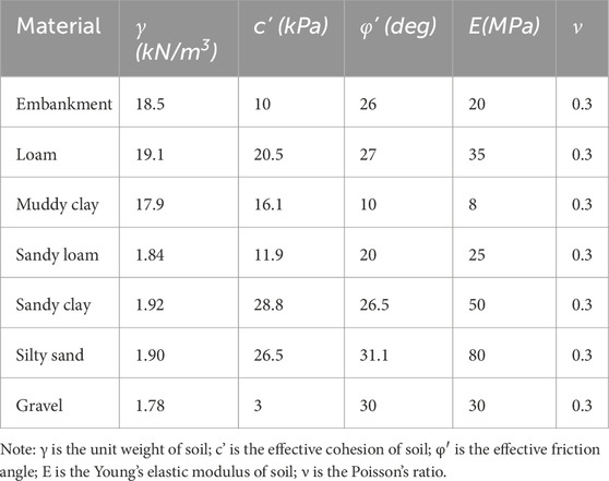
The embankment fill, gravel of GRSP, and foundation soils are modeled as linearly elastic, perfectly plastic materials obeying the Mohr–Coulomb failure criteria. The Mohr–Coulomb model requires five parameters: effective cohesion, inner friction angle, dilatancy angle, effective Young’s modulus, and Poisson’s ratio, as outlined in Table 2. These parameters were derived from the geotechnical investigation report for Yancheng, Jiangsu Province, with the dilatancy angle assumed to be 0°. The pile is modeled as an isotropic linear elastic material with a Young’s modulus of 20 GPa and a Poisson’s ratio of 0.2. The geogrid in GRSP is modeled as a geogrid element incorporated into the software, which can sustain axial tensile force only, and the tensile stiffness of geogrid is 1,125 kN/m. Furthermore, the interface yield stress is also determined by the Mohr–Coulomb failure criteria, and a reduction factor of 0.7 is applied to the pile–soil contact face and geogrid–gravel contact face, based on the shear strength of GRSP gravel and foundation soil.
The modeling procedure consists of two main steps: to construct initial soil stress field and to model six-staged embankment construction. The staged embankment construction includes six filling steps to the top of the embankment in simulation.
The parametric study on the characteristics of the GRSP was carried out, and the baseline case is the field testing mentioned above. The values of all influencing factors are listed in Table 3. In addition, one parameter was deviated from the baseline case at one time to explore the influences of the specific factor. The variation ranges of all the factors cover the typical range in practice.
4 Measured and computed results
4.1 Performance of the geogrid-reinforced soil platform pile-supported embankment
The settlements of the pile and soil are illustrated in Figure 2A. Settlement plates measured the settlements. With the increase in the embankment height, the settlements of both the pile and soil increase, with the similar settlement trends. At the beginning of the embankment filling, the settlements of the pile and soil are quite small, and the settlement rate increases slowly, especially for the pile settlement. As the embankment reaches 2.5–3.0 m high, the settlement rate increases obviously, and the settlement rate of soil is larger than that of piles. The filling height of each step has a significant effect on the settlement rate (i.e., embankment height from 3.7 m to 5.7 m). Following the completion of embankment construction, settlement due to the gradual dissipation of excess pore water pressure accumulated during construction that continued for several months.
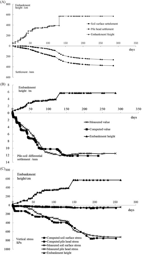
Figure 2. (A) Measured settlement of the pile head and soil surface. (B) Measured and computed differential settlement of the pile head and soil surface. (C) Measured and computed pressure acted on the pile head and soil surface.
Figures 2B, C show the differential settlement and stress ratio of the pile and soil, respectively. The differential settlement obtained by subtracting the pile settlement from the foundation soil surface settlement reflects the deformation of GRSP. The stress ratio of pile to soil, defined as vertical stress acting on the pile head to that on the soil surface, was measured by earth pressure cells. The stress ratio reflects the load redistribution between the pile and soil due to deformation of the GRSP. At the beginning of embankment construction (H < 1 m), the settlement of the surrounding soil is small under the low embankment height. Consequently, the vertical stresses of the pile head and soil surface are almost identical, and the vertical stress concentration at the pile head is not obvious. When the embankment is higher than 1 m, soil settlement increases and capacity develops. In terms of the distinct difference of moduli of pile concrete and soil, the settlement of the pile is smaller, resulting in the pile–soil differential settlement. During this period, the effect of the GRSP is induced. The geogrid in the GRSP works as tensile nets between piles, transferring loads from soils to the piles through the tensile force in the geogrid and the friction force between the geogrid and platform gravel. With the embankment up to approximately 3.7 m high, the vertical stress on the soil surface increases slightly, whereas the pile–soil differential settlement and the vertical stress on the pile head increase significantly. During the following construction, the vertical stress on the soil surface and the pile–soil differential settlement is almost unchangeable, whereas the vertical stress on the pile head still increases remarkably. The vertical stress on the pile head became stable after the completion of embankment construction, and the stable stress ratio of the pile and soil is 16.5, with the final pile–soil differential settlement of 114 mm.
According to the whole response process of the pile and soil in the construction of the embankment, including settlement and vertical stress, the GRSP plays an important role among the pile, foundation soil, and embankment filling. When the embankment height is less than 1 m, stresses on the pile and soil increase subtly, yet the pile–soil differential settlement is noticeable, which mainly results from the settlement of soil, and the existence of GRSP gravel keeps the surrounding soil carrying the load in the surface subsidence stage. When the embankment height reaches 3.7 m and the tensile force in the geogrid is stimulated gradually due to the increasing pile–soil differential settlement, the stiffness of the geogrid in GRSP limits the load applied on the soil surface and transfers the corresponding load to the pile head, which was reflected from the slight increase in soil stress and the prominent increase in pile stress. When the embankment was built from 3.7 m to 5.7 m, the pile and soil settle as an entirety and pile–soil differential settlement is nearly identical, revealing the stability of the interaction of pile and soil. The additional load at this stage is almost completely carried by pile-supported GRSP, as indicated by the slight increase in soil stress and prominent increase in pile stress, and the continuing soil settlement is mainly caused by the settlement of the pile. The comparison results of the pile–soil differential settlement and the vertical stresses on the pile head and soil surface are illustrated in Figures 2B, C, and the computed results are in a good agreement with the measured values.
Figure 3A displays the development processes of the stress ratio of pile to soil with different GRSP construction methods. The GRSP construction method has a significant influence on the developing mode of the stress ratio of the pile to soil and small influence on the final value of the stress ratio of the pile to soil, which is 17.0 and 16.5, respectively. The stress ratio of the pile to soil with the first type of the GRSP construction method is always larger than that of the second method, and the difference in the stress ratio of pile to soil between the two methods decreases in the whole construction process. With well-compacted GRSP (Method 1), the geogrid tensile force increases distinctly at the early stage and increases slowly at the later stage of embankment construction, owing to the plasticity of the geogrid under large tensile forces. In this study, the main method used for compacting the soil platform on the site is vibratory compaction, with engineering requirements stipulating that the compaction degree must exceed 90%. In contrast, the geogrid tensile force nearly linearly increases for the un-compacted GRSP case (Method 2) during construction.

Figure 3. (A) Measured stress concentration of the pile and soil with different GRSPs. (B) Measured lateral displacement of the ground surface at the embankment toe.
Figure 3B shows the influences of the GRSP construction method on the horizontal displacement on the foundation surface at the embankment toe. It can be seen that during construction, the horizontal displacement is generally smaller for the well-compacted GRSP compared to the un-compacted GRSP. With the well-compacted GRSP, the final ground surface lateral displacements at the embankment toe are smaller, and the values of lateral displacement are 17.5 mm and 22.5 mm for the embankment with the compacted and un-compacted GRSP, respectively. The larger compaction of GRSP soil benefits both the reduction of embankment horizontal displacement and stability of embankment.
4.2 Load transfer mechanism of geogrid-reinforced compacted
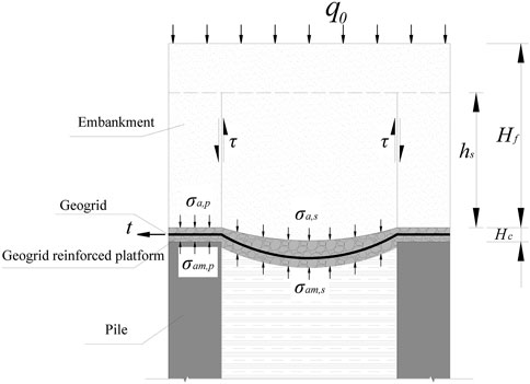
The interactions among piles, foundation soil, embankment fill, and GRSP are schematically explained in Figure 4. Owing to the large stiffness difference between piles and foundation soil, the embankment fill between piles has a tendency to move downward under the self-weight of fill. The movement is partially constrained by the shear resistance (
Based on the load transfer mechanism, several coefficients are introduced to discuss the effects of GRSP on the soil arching effect of the embankment, tensioned membrane effect of geosynthetics, and stress concentration of pile, including i) the stress concentration ratio of the pile head to the soil surface (
The stress concentration ratio of the pile head to the soil surface is defined as Equation 1
where
The degree of the soil arching effect is given by Equation 2 (as proposed in (McNulty, 1965))
where
The degree of composite effects of soil arching and tensioned membrane is given by Equation 3
where
The degree of tensioned membrane is defined as Equation 4
where
4.3 Influences of the GRSP modulus on stresses and settlements of pile and soil
4.3.1 Influences of the GRSP modulus on stresses
The degree of the stress concentration from soil to pile is typically evaluated with the stress concentration ratio of the pile head to soil surface (n). The higher the n, the additional loads are transferred to the pile from soil. As shown in Figure 5A, n increases with the increase in the elastic modulus of the GRSP material. As the elastic modulus increases from 15 MPa to 100 MPa, n increases from 10.1 to 18.6. As the elastic modulus of the GRSP increases, its deformation resistance improves, allowing more load to be effectively transferred to the piles, with the GRSP functioning as a deformed beam between the piles.
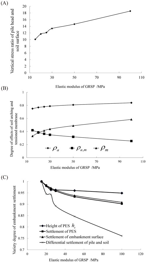
Figure 5. (A) Influence of the elastic modulus of GRSP on the stress concentration ratio of pile to soil (
Except for the stress concentration ratio, the load transfer mechanisms are affected at different degrees owing to the variety of the GRSP modulus, as presented in Figure 5B. With the increase in the GRSP material modulus, the soil arching ratio (
4.3.2 Influences of the GRSP modulus on settlements
As shown in Figure 5C, the elastic modulus of GRSP affects the settlements of the pile and soil, including the differential settlement of the pile and soil, the settlement of the embankment surface, the height of the plane of equal settlement (PES)
4.4 Influences of GRSP thickness on stresses and settlements of pile and soil
4.4.1 Influences of GRSP thickness on stresses
Figure 6A presents the stress concentration ratio of the pile head to the soil surface versus the thickness of GRSP. Clearly, the stress concentration ratio of pile to soil linearly increases with an increase in the thickness of GRSP in this analysis. In other words, the stress concentration ratio of pile to soil increases with an increase in the thickness of GRSP. This result can be explained that when the GRSP is thicker, the deformation resistance of GRSP can be strengthened, which is similar to the increase in the GRSP modulus mentioned above, and more stresses can be transferred to piles through GRSP. As the thickness increases from 10 cm to 50 cm, the stress concentration ratio increases by 46.5% from 9.1 to 13.4.
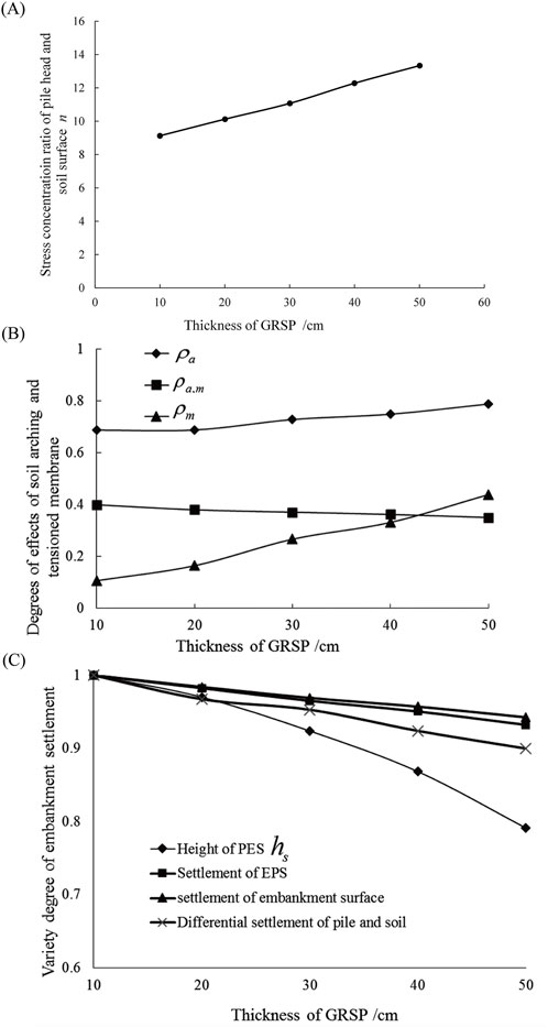
Figure 6. (A) Influence of the thickness of GRSP on the stress concentration ratio of pile to soil (
The different degrees of effects of soil arching and tensioned membrane are plotted against the GRSP thickness in Figure 6B. Consistent with the stress concentration ratio, the thicker the GRSP, the higher the soil arching ratio (
4.4.2 Influence of GRSP thickness on settlements
Figure 6C demonstrates the influence of GRSP thickness on the settlements of pile and soil, including the differential settlement of pile and soil, the settlement of the embankment surface, the height of the plane of equal settlement (PES)
4.5 Influence of GRSP shear resistance on stresses and settlements of pile and soil
4.5.1 Influence of GRSP shear resistance on stresses
The shear resistance of the GRSP material (i.e., friction angle and cohesion) is expected to affect the performance of the pile and soil. In practical applications, gravel or sand is commonly used as the GRSP material due to its effectiveness in dissipating excess pore water pressure within the soil. Consequently, the variation in cohesion is minimal, and the effect of GRSP material cohesion is disregarded in this analysis. However, the influence of the friction angle of the GRSP material is analyzed as below.
As shown in Figure 7A, the friction angle of the GRSP material influences the stress concentration ratio of the pile head to the soil surface. Noticeably, the stress concentration ratio of pile to soil linearly increases with an increase in the friction angle of the GRSP material. In other words, it is effective to increase the stress concentration ratio of pile to soil when the friction angle of the GRSP material increases. The results can be explained by the fact that the larger friction angle induced the higher shear resistance and more loads were transferred to the pile head from soil, which is the same as that of the increase in GRSP modulus or thickness. When the friction angle increases from 10°to 40°, the stress concentration ratio increases from 10.1 to 14.7.
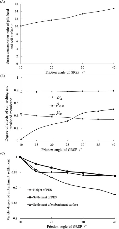
Figure 7. (A) Influence of friction angles of GRSP on the stress concentration ratio of pile to soil (
The different degrees of effects of soil arching and tensioned membrane versus friction angle are illustrated in Figure 7B. Consistent with the stress concentration ratio, with the increase in the friction angle, both the soil arching ratio (
As shown in Figure 7C, the friction angle of the GRSP material has effects on the settlements of the pile and soil, including the differential settlement of the pile and soil, the settlement of the embankment surface, the height of the plane of equal settlement (PES)
4.6 Influence of geogrid tensile stiffness on stresses and settlement of pile and soil
4.6.1 Influence of geogrid tensile stiffness on stresses
Figure 8A demonstrates the stress concentration ratio of the pile head and soil surface versus the tensile stiffness of the geogrid. Clearly, the stress concentration ratio of the pile to soil increased significantly with an increase in the tensile stiffness of the geogrid in GRSP. In other words, the stress concentration ratio of the pile to soil can be improved by increasing the tensile stiffness of the geogrid. This result is in good agreement with the findings obtained by Han and Gabr (2002). It can be explained that when the tensile stiffness of the geogrid is higher, the deformation resistance of the GRSP is enhanced. This effect is similar to the impact of other physical or mechanical parameters of the GRSP mentioned earlier, such as increased elastic modulus, thickness, and shear resistance, enabling greater load transfer to the piles through the GRSP between them. As the tensile stiffness increases from 300 kN/m to 2,250 kN/m, the stress concentration ratio increases by 58.9% from 10.4 to 16.5.
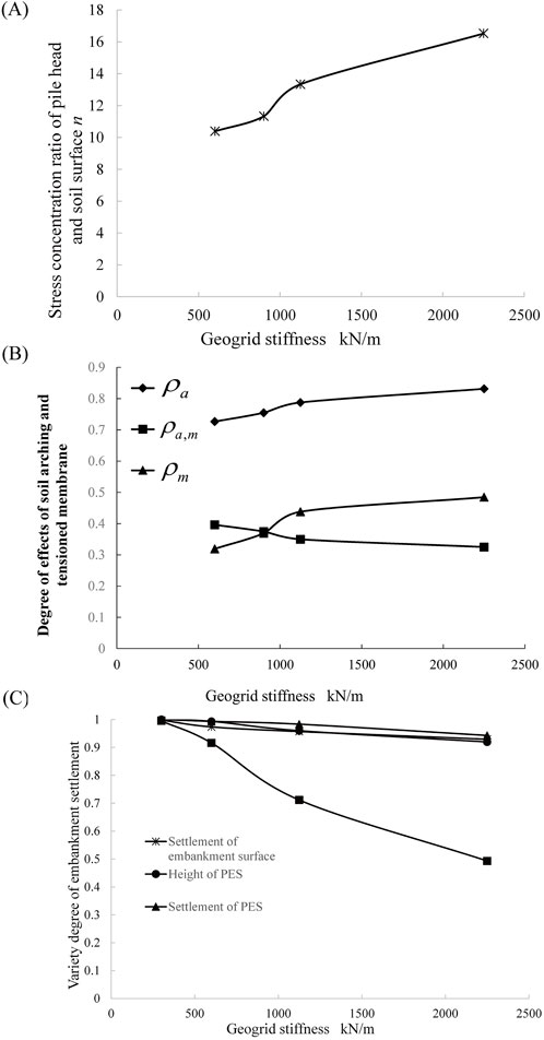
Figure 8. (A) Influence of tensile stiffness of the geogrid on the stress concentration ratio of pile to soil (
The influences of geogrid tensile stiffness on the effects of soil arching and tensioned membrane are plotted in Figure 8B. Consistent with the stress concentration ratio, the higher the tensile stiffness of the geogrid, the larger the soil arching ratio (
4.6.2 Influence of geogrid tensile stiffness on settlements
As illustrated in Figure 8C, the tensile stiffness of the geogrid also has an influence on the settlements of pile and soil, including the differential settlement of pile and soil, the settlement of the embankment surface, the height of the plane of equal settlement (PES)
4.7 Influences of geogrid layers and placement on stresses and settlements of pile and soil
4.7.1 Influence of geogrid layers and placement on stresses
Figure 9A presents the stress concentration ratio of the pile head to the soil surface versus the geogrid layers and placement. The stress concentration ratio of the pile to soil increases with the increase in the geogrid layers and the lowering placement of the geogrid in GRSP. In other words, the stress concentration ratio of the pile to soil is strengthened by increasing the layers of the geogrid and lowering the placement elevation of the geogrid in GRSP. These results can be explained by the fact that when the geogrid layers increase or the placement elevation of geogrid reduce, the deformation resistance of GRSP under pile penetration is strengthened, which was similar to the increase in the geogrid tensile stiffness, and additional loads can be transferred to piles through GRSP between piles. As the geogrid layers increase from single layer to triple layers, the stress concentration ratio increases by 11% from 12.8 to 14.2. When one of the geogrid layers is shifted from the top of GRSP to the bottom in the double layer cases, the stress concentration ratio increases slightly from 13.3 to 13.6 at an approximately 2.2% increasing rate.
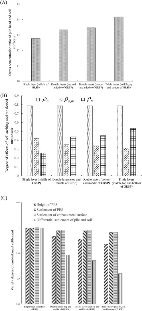
Figure 9. (A) Influence of layer and placement of the geogrid in GRSP on the stress concentration ratio of pile to soil (
The different degrees of effects of soil arching and tensioned membrane versus geogrid layers and placement are illustrated in Figure 9B. Consistent with the stress concentration ratio, the more the geogrid layers, the larger the soil arching ratio (
4.7.2 Influence of geogrid layers and placement on settlements of pile and soil
As shown in Figure 9C, the layers and placement of the geogrid in GRSP affect the settlements of pile and soil, including the differential settlement of the pile and soil, the settlement of the embankment surface, the height of the plane of equal settlement (PES)
5 Discussion
The influences of various factors of GRSP on the stress concentration ratio of pile to soil, soil arching effect, tensioned membrane effect, differential settlement of pile and soil, settlement of embankment surface, and height of PES in embankment and its settlement are summarized below.
According to the definitions of the composite ratio of soil arching and tensioned membrane effects (
Various factors of the GRSP, including elastic modulus, thickness, friction angle, tensile stiffness, and the number of geogrid layers, all have positive effects. Increasing these factors facilitates greater load transfer from the soil to the piles and reduces embankment settlement. However, increases in various GRSP factors lead to different load transfer processes. For example, the increase in these influencing factors shows negative effects on soil arching and positive effects on the tensioned membrane effect. The influencing degree of each influencing factor has been introduced to evaluate the variation degree of investigated performance parameters, such as the stress concentration ratio of pile and soil, soil arching effect, tensioned membrane effect, differential settlement of pile and soil, settlement of embankment surface, and the height of PES in the embankment and its settlement. The influencing degree is defined as the ratio of the maximum variation of the performance parameter to the mean value of the performance parameter. As an example, the stress concentration ratios of pile to soil for the GRSP elastic modulus equal to 15, 20, 25, 30, 50, and 100 MPa are 10.1, 11.7, 12.1, 13.5, 14.7, and 18.6, respectively. The maximum variation of the stress concentration ratio of pile to soil within the variation range in this analysis is 18.6–10.1 = 8.5, and the mean value of the stress concentration ratio of the pile and soil is (10.1+11.7+12.1+13.5+14.7+18.6)/6 = 13.45. Hence, the degree of influence of the GRSP elastic modulus on the stress concentration ratio of the pile to soil is calculated as (8.5/13.45)×100% = 63.2%. The calculated degree of influence for each factor on each investigated performance parameter is listed in Table 4.
According to the results shown in Table 4, the elastic modulus of GRSP has significant influences on the performance of the pile-supported embankment, especially on the stress concentration ratio of pile to soil, the composite soil arching and tensioned membrane ratio, the settlement of the embankment surface, and PES. The thickness of GRSP affected the height of PES and tensioned membrane ratio notably, compared to other factors, and the influence of the larger compression value for thicker GRSP should be taken into account. The friction angle of the GRSP material influences the tensioned membrane ratio significantly as well. The tensile stiffness of the geogrid has a significant impact on the soil arching ratio and the differential settlement of soil and pile. The influence of the geogrid layer on the tensioned membrane ratio is noticeable. The influence of geogrid placement on the performance of the pile-supported embankment is practically negligible. The settlement of the embankment surface and the stress concentration ratio of pile to soil are the important controlling indexes in practice; thus, the elastic modulus, tensile stiffness, and friction angle can be considered the three most important design parameters among the discussed influencing factors.
6 Conclusion
Based on the field monitoring and numerical parametric studies on the influences of GRSP on the performances of pile-supported embankment, the following conclusions can be drawn:
(1) By comparing field observation results of the embankment sections with different GRSPs, it is found that the compaction of the GRSP material affects the developing process of the stress concentration ratio of pile to soil, as well as the lateral displacement of the embankment. If the GRSP material is well compacted, the stress concentration ratio of the pile to soil increases distinctly at the early stage of embankment construction, and the lateral displacement becomes smaller compared to the un-compacted case.
(2) In reference to the definition of the soil arching ratio (
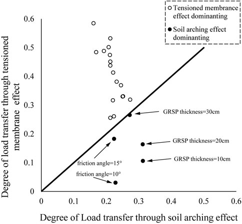
(3) A number of factors of GRSP influence not only the results of load transfer between pile and soil (i.e., the stress concentration ratio of pile to soil and the settlement of embankment surface) but also the process of load transfer (i.e., soil arching ratio, tensioned membrane ratio, and the differential settlement of pile and soil). The soil arching and tensioned membrane effects effectively reduce the load applied on the ground soil, with the tensioned membrane effect of GRSP typically playing a predominant role in transferring loads from soil to piles compared to the soil arching effect.
(4) With an increase in the GRSP factor (elastic modulus, thickness, friction angle, tensile stiffness, and layers of the geogrid), the load transferred to piles increases, and all the corresponding settlements decrease at different degrees. However, the soil arching effect in the embankment and the tensioned membrane effect in the GRSP exhibit opposite trends: the soil arching effect is diminished, while the tensioned membrane effect is enhanced.
(5) Using embankment surface settlement and the stress concentration ratio between piles and soil as key control indices, the elastic modulus, tensile stiffness, and friction angle of the GRSP are identified as the three most critical design parameters. Specifically, based on our case studies, we recommend using materials with higher elastic modulus and greater friction angles, such as well-compacted sand or gravel, as the soil platform. Additionally, incorporating high-strength geogrids as reinforcement in the GRSP is advised to effectively reduce the overall settlement of the embankment. However, beyond these three parameters, the placement of geogrids within the GRSP has a negligible impact on the performance of the pile-supported embankment.
Data availability statement
The original contributions presented in the study are included in the article/Supplementary Material; further inquiries can be directed to the corresponding author.
Author contributions
ZZ: data curation, investigation, methodology, software, and writing–original draft. LZ: conceptualization, supervision, and writing–review and editing.
Funding
The author(s) declare that financial support was received for the research, authorship, and/or publication of this article. The authors acknowledge financial support from the National Science Foundation of China (No. 51890912).
Conflict of interest
Author ZZ was employed by Suzhou New District Testing Corporation.
The remaining author declares that the research was conducted in the absence of any commercial or financial relationships that could be construed as a potential conflict of interest.
The reviewer XN declared a shared affiliation with the author LZ to the handling editor at the time of review.
Publisher’s note
All claims expressed in this article are solely those of the authors and do not necessarily represent those of their affiliated organizations, or those of the publisher, the editors, and the reviewers. Any product that may be evaluated in this article, or claim that may be made by its manufacturer, is not guaranteed or endorsed by the publisher.
References
Badakhshan, E., Noorzad, A., Bouazza, A., Zameni, S., and King, L. (2020). A 3D-DEM investigation of the mechanism of arching within geosynthetic-reinforced piled embankment. Int. J. SOLIDS Struct. 187, 58–74. doi:10.1016/j.ijsolstr.2019.03.035
Blanc, M., Rault, G., Thorel, L., and Almeida, M. (2013). Centrifuge investigation of load transfer mechanisms in a granular mattress above a rigid inclusions network. Geotext. Geomembr. 36, 92–105. doi:10.1016/j.geotexmem.2012.12.001
Borges, J. L., and Marques, D. O. (2011). Geosynthetic-reinforced and jet grout column-supported embankments on soft soils: numerical analysis and parametric study. Comput. Geotech. 38, 883–896. doi:10.1016/j.compgeo.2011.06.003
Briançon, L., and Simon, B. (2012). Performance of pile-supported embankment over soft soil: full-scale experiment. J. Geotech. Geoenvironmental Eng. 138, 551–561. doi:10.1061/(ASCE)GT.1943-5606.0000561
Chen, R. P., Xu, Z. Z., Chen, Y. M., Ling, D. S., and Zhu, B. (2010). Field tests on pile-supported embankments over soft ground. J. Geotech. Geoenvironmental Eng. 136, 777–785. doi:10.1061/(ASCE)GT.1943-5606.0000295
Du, W., Nie, R., Qi, Y., Ruan, B., and Mo, F. (2024). Investigation on the static performance of geogrid reinforced aeolian sand railway embankment: field test and discrete element simulation. Geotext. Geomembr. 52, 736–752. doi:10.1016/j.geotexmem.2024.03.012
Esmaeili, M., Naderi, B., Neyestanaki, H. K., and Khodaverdian, A. (2018). Investigating the effect of geogrid on stabilization of high railway embankments. Soils Found. 58, 319–332. doi:10.1016/j.sandf.2018.02.005
Ghosh, B., Fatahi, B., Khabbaz, H., Nguyen, H. H., and Kelly, R. (2021). Field study and numerical modelling for a road embankment built on soft soil improved with concrete injected columns and geosynthetics reinforced platform. Geotext. Geomembr. 49, 804–824. doi:10.1016/j.geotexmem.2020.12.010
Han, J., and Gabr, M. A. (2002). Numerical analysis of geosynthetic-reinforced and pile-supported earth platforms over soft soil. J. Geotech. Geoenvironmental Eng. 128, 44–53. doi:10.1061/(ASCE)1090-0241(2002)128:1(44)
Huang, J., and Han, J. (2010). Two-dimensional parametric study of geosynthetic-reinforced column-supported embankments by coupled hydraulic and mechanical modeling. Comput. Geotech. 37, 638–648. doi:10.1016/j.compgeo.2010.04.002
Huang, J., Han, J., and Oztoprak, S. (2009). Coupled mechanical and hydraulic modeling of geosynthetic-reinforced column-supported embankments. J. Geotech. Geoenvironmental Eng. 135, 1011–1021. doi:10.1061/(ASCE)GT.1943-5606.0000026
Khosrojerdi, M., Qiu, T., Xiao, M., and Nicks, J. (2018). Numerical investigation on the performance of geosynthetic-reinforced soil piers under axial loading: 3rd international foundation congress and equipment expo 2018: developments in earth retention, support systems, and tunneling, IFCEE 2018. Geotech. Spec. Publ. 2018-March, 99–108. doi:10.1061/9780784481608.010
Liu, H., Kong, G., Chu, J., and Ding, X. (2015). Grouted gravel column-supported highway embankment over soft clay: case study. Can. Geotech. J. 52, 1725–1733. doi:10.1139/cgj-2014-0284
Liu, H. L., Ng, C. W. W., and Fei, K. (2007). Performance of a geogrid-reinforced and pile-supported highway embankment over soft clay: case study. J. Geotech. Geoenvironmental Eng. 133, 1483–1493. doi:10.1061/(ASCE)1090-0241(2007)133:12(1483)
McNulty, J. (1965). An experimental study of arching in sand. Available at: https://api.semanticscholar.org/CorpusID:108153817.
Okyay, U. S., Dias, D., Thorel, L., and Rault, G. (2014). Centrifuge modeling of a pile-supported granular earth-platform. J. Geotech. Geoenvironmental Eng. 140, 04013015. doi:10.1061/(ASCE)GT.1943-5606.0001004
Pham, H. T. V., Suleiman, M. T., and White, D. J. (2004). Numerical analysis of geosynthetic-rammed aggregate pier supported embankments. Geotech. Eng. Transp. Proj., 657–664. doi:10.1061/40744(154)52
Rowe, R. K., and Liu, K.-W. (2015). Three-dimensional finite element modelling of a full-scale geosynthetic-reinforced, pile-supported embankment. Can. Geotech. J. 52, 2041–2054. doi:10.1139/cgj-2014-0506
Rui, R., Han, J., van Eekelen, S. J. M., and Wan, Y. (2019). Experimental investigation of soil-arching development in unreinforced and geosynthetic-reinforced pile-supported embankments. J. Geotech. Geoenvironmental Eng. 145, 04018103. doi:10.1061/(ASCE)GT.1943-5606.0002000
Shen, P., Xu, C., and Han, J. (2020). Geosynthetic-reinforced pile-supported embankment: settlement in different pile conditions. Geosynth. Int. 27, 315–331. doi:10.1680/jgein.19.00015
Stewart, M. E., and Filz, G. M. (2005). “Influence of clay compressibility on geosynthetic loads in bridging layers for column-supported embankments,” in Contemporary issues in foundation engineering (Austin, Texas, United States: American Society of Civil Engineers), 1–14. doi:10.1061/40777(156)8
Stewart, M. E., Navin, M. P., and Filz, G. M. (2004). Analysis of a column-supported test embankment at the I-95/Route 1 interchange. Geotech. Eng. Transp. Proj., 1337–1346. doi:10.1061/40744(154)123
Terqueux, C., Racinais, J., Briançon, L., Pantet, A., and Gotteland, P. (2023). “Full scale experiment of a geosynthetic-reinforced piled embankment,” in Geosynthetics: leading the way to a resilient planet (London: CRC Press).
Terzaghi, K. (1936). Stress distribution in dry and in saturated sand above a yielding trap-door. Available at: https://api.semanticscholar.org/CorpusID:132913229.
van Eekelen, S. J. M., Venmans, A. a. M., Bezuijen, A., and van Tol, A. F. (2020). Long term measurements in the Woerden geosynthetic-reinforced pile-supported embankment. Geosynth. Int. 27, 142–156. doi:10.1680/jgein.17.00022
Wu, D., Luo, C., Gao, Z., Li, D., and Xu, C. (2022). Effect of different reinforced load transfer platforms on geosynthetic-reinforced pile-supported embankment: centrifuge model test. KSCE J. Civ. Eng. 26, 630–649. doi:10.1007/s12205-021-0623-7
Xing, H., Zhang, Z., Liu, H., and Wei, H. (2014). Large-scale tests of pile-supported earth platform with and without geogrid. Geotext. Geomembr. 42, 586–598. doi:10.1016/j.geotexmem.2014.10.005
Xu, C., Wu, D., Song, S., and Liu, B. (2018). “Centrifuge model tests of basal reinforcement effects on geosynthetic-reinforced pile-supported embankment,” in Proceedings of geoshanghai 2018 international conference: ground improvement and geosynthetics. Editors L. Li, B. Cetin, and X. Yang (Singapore: Springer-Verlag Singapore Pte Ltd), 279–287. doi:10.1007/978-981-13-0122-3_31
Yan, M., Song, X., Xiao, H., Guo, S., Zhang, H., and Chango, I. V. L. (2022). Analysis of load transfer in geosynthetic-reinforced pile-supported embankments. 2022 16TH IEEE Int. Conf. SIGNAL Process. (ICSP2022) 1, 354–358. doi:10.1109/ICSP56322.2022.9965213
Zhang, X., Zhuang, Y., Hu, S., and Dong, X. (2022). A simplified method for assessing the serviceability performance of geosynthetic reinforced and pile-supported embankment. Geotext. Geomembr. 50, 1214–1229. doi:10.1016/j.geotexmem.2022.08.006
Keywords: pile-supported embankment, reinforced soil platform, geogrid, load transfer, field test, numerical analysis
Citation: Zhao Z and Zheng L (2024) Influences of the geogrid-reinforced soil platform on the performance of pile-supported embankment. Front. Earth Sci. 12:1486831. doi: 10.3389/feart.2024.1486831
Received: 20 September 2024; Accepted: 25 November 2024;
Published: 12 December 2024.
Edited by:
Yifei Sun, Taiyuan University of Technology, ChinaReviewed by:
Xiangfeng Guo, South China University of Technology, ChinaXiaodong Ni, Hohai University, China
Li Cheng, University of Western Australia, Australia
Congyang Yu, University of Western Australia, Australia, in collaboration with reviewer LC
Copyright © 2024 Zhao and Zheng. This is an open-access article distributed under the terms of the Creative Commons Attribution License (CC BY). The use, distribution or reproduction in other forums is permitted, provided the original author(s) and the copyright owner(s) are credited and that the original publication in this journal is cited, in accordance with accepted academic practice. No use, distribution or reproduction is permitted which does not comply with these terms.
*Correspondence: Leiming Zheng, emxtMDMyN0BoaHUuZWR1LmNu
 Zhihui Zhao1
 Leiming Zheng