- 1School of Civil Engineering and Architecture, Anhui University of Science and Technology, Huainan, Anhui, China
- 2Ningxia Wangwa Coal Industry Co. Ltd., Guyuan, China
The prevention and control of deformation and instability in high-stress soft rock roadways hold significant value for ensuring normal mine production and the safety of personnel and equipment. This study focuses on the pedestrian descent from the 11th mining area of the Yindonggou Mine, providing a thorough elucidation of the internal mechanisms leading to large deformation and instability in the roadway. It accounts for the influences of surrounding rock lithology, geological structure, and support measures. Consequently, based on the theory of rock instability, corresponding tunnel repair measures and control strategies were proposed and verified through field application. The results indicate that: (1) High strength dispersion and insufficient support resistance of the expansive weak and fractured surrounding rock sections are critical factors inducing significant deformation in the soft rock roadway of Yindonggou Mine. (2) The primary factor contributing to the large deformation disaster in the Yindonggou Mine roadway is the disturbance caused by proximate coal seam mining, which exacerbates the conflict between the high structural stress in the strata and the low strength of the surrounding rock. High-level stress initially leads to deformation in the weakly supported floor, followed by deformation and instability of the surrounding rock, ultimately culminating in the collapse of the entire roadway section. (3) Soft rock support should be designed with varying schemes tailored to the rock type and structural stress of the surrounding rock in the tunnel. For tunnels with carbon mudstone and expansive soft rock as the main roof and floor components, the support plan should primarily focus on enhancing the support stiffness of the tunnel wall. Conversely, for tunnels where sandstone predominates as the roof and floor material, the support plan should aim to restore the three-dimensional stress state of the surrounding rock and fully utilize its self-supporting capacity. (4) Based on the engineering conditions of pedestrian downhill in No.11 mining area of Yindonggou Mine, a differentiated support scheme is proposed. The feasibility and effectiveness of each support scheme are verified by numerical simulation, so as to provide valuable reference and enlightenment for similar projects.
1 Introduction
With the advancement of underground resource exploitation, engineering challenges in high tectonic stress environments have become increasingly prominent (Fa-you et al., 2022; Kang et al., 2024a; Kang et al., 2024b; Shi et al., 2019; Shi et al., 2022). In critical sectors such as mining, water conservancy, and transportation, ensuring the stability of soft rock tunnels under these conditions is paramount (Wu et al., 2020; Wu et al., 2022; Wu et al., 2024). Soft rock, characterized by low strength, high plasticity, significant water absorption, and expansion tendencies, is prone to substantial deformation under high tectonic stress (Shi et al., 2023a; Shi et al., 2023b). This phenomenon undermines project safety and economic viability by causing roadway distortion (Guo et al., 2017; Guo et al., 2018; Yang et al., 2020; Yu et al., 2019). Such deformation accelerates the deterioration of support structures, increases maintenance costs, and causes secondary hazards, thereby threatening personnel safety (Yang Y. et al., 2023; Zhang et al., 2022). Hence, studying the mechanisms of large deformations in soft rock tunnels within high tectonic stress environments and formulating effective control strategies is of great significance. This research is crucial for ensuring the smooth operation and economic benefits of underground projects.
Currently, scholars at home and abroad have conducted extensive research on the large deformation of soft rock roadways under high tectonic stress. Through theoretical analysis, physical model testing, and numerical simulation, the deformation and failure mechanisms of deep soft rock roadways and the improvement of control technologies are investigated. Regarding the deformation mechanism, Alejano et al. (2012) put forward a simplified approximate equation for the plastic radius of tunnel excavation in strain-softening rock masses. This equation can be combined with the existing longitudinal deformation profile estimation technology to acquire a more realistic approach for calculating the longitudinal deformation profile of strain-softening rock masses. Martino and Chandler (2004) discovered that in-situ stress, tunnel shape and its orientation relative to the maximum stress, excavation method, subtle changes in rock structure, application of thermal load, variations in pore pressure, and the occurrence of nearby excavation all influence the development of the expansion zone. Varas et al. (2005) utilized FDM-based code to create and analyze a series of tunnel models excavated in strain-softening materials, and observed bifurcation and localization phenomena via this model. In the research on control technology, Li et al. (2024) investigated the mechanical evolution characteristics of the surrounding rock of deep soft rock roadways under different lateral pressure coefficients, as well as the distribution laws of the displacement field and failure field, and optimized support technology. Mark (2000) deliberated on the anchoring mechanism, prestress, length, bearing capacity, installation time, and quality of roof bolts based on the research results in recent years. Additionally, he introduced the design methods based on experimental verification, numerical simulation, and roof monitoring from around the world. Basarir et al. (2019) employed a global-local model to analyze roadway stability and put forward an innovative support system, evaluating its performance. Although previous studies have developed and verified various support measures, they show limitations in dealing with large deformations in soft rock tunnels under extreme tectonic stresses, such as partial revelation of mechanisms, lack of specific support scheme design, and reliance on single control methods (Guo et al., 2021; Shan et al., 2022). Therefore, studying the mechanisms of large deformations in soft rock tunnels within high tectonic stress environments and formulating effective control strategies is of great significance. This research is essential for ensuring the smooth operation and economic benefits of underground projects.
To address these prevailing issues, a profound analysis of the multifaceted factors and underlying mechanisms driving large deformations in soft rock tunnels under intense tectonic stress is imperative. This necessitates a systematic evaluation of the applicability and constraints of existing control technologies, alongside the exploration of novel and more effective strategies for tunnel deformation mitigation. These endeavors aim to provide a valuable reference and guidance framework for tackling analogous engineering challenges. Focusing on the pedestrian descent in the 11th mining area of Yindonggou Mine, this study embarks on a comprehensive investigation, initially examining the intricate interplay between surrounding rock properties, geological structures, and support measures. This holistic approach aims to unravel the mechanisms underpinning the large deformations and instability observed in soft rock roadways. Building upon this foundational understanding, we integrate theories pertaining to surrounding rock instability to propose tailored roadway rehabilitation measures and control strategies. Subsequently, we validate the efficacy of these proposals through rigorous on-site implementation and assessment.
2 The geological conditions of the mine
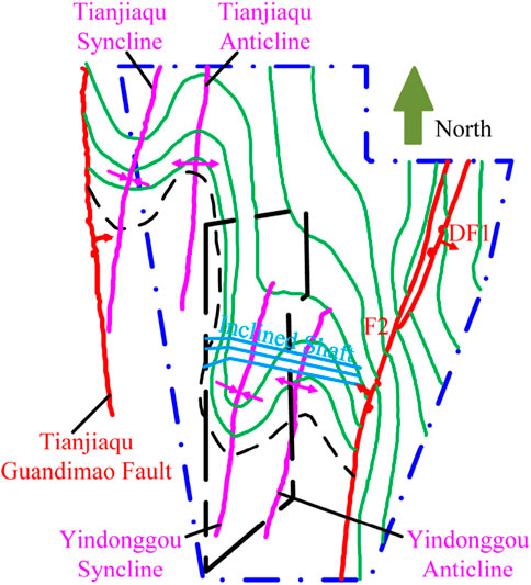
The Yindonggou shaft field, situated in the northerly expanse of the Wangwa Mining Area within Panyang County, Ningxia Hui Autonomous Region, is strategically excavated through a network of inclined shafts that progressively descend from west to east. The geological structure distribution of the Yindonggou coal mine is shown in Figure 1. The topography of this mining region is characteristic of the rolling hills that define the loess plateau, featuring an elevation range spanning from a peak of +1903 m above sea level to a nadir of +1,530 m, with an average erosion datum at trench base standing at +1,600 m. Geologically, the field area is marked by prominent folds, notably the Yindonggou oblique and dorsal slopes, which exhibit an impressive amplitude of approximately 300 m. The predominant tectonic feature is the F2 reverse fault, distinguished by a steep dip angle approaching 70° and a significant throw varying from 150 to 300 m.
3 Cave deformation characteristics and cause analysis
In the present study, the pedestrian descent in Mine Area 11 is utilized as a specialized transit corridor, strategically connecting the +1380 m level to the +1290 m level of the mine and traversing an inclined length of 385 m. The design of this roadway conforms to a precise straight-walled semi-circular arch configuration and is meticulously dimensioned with a width of 4,600 mm, a straight wall height of 1900 mm, and an overall height of 4,200 mm. This configuration not only guarantees the structural integrity of the passageway but also optimizes pedestrian flow and safety, thereby embodying the essence of civil engineering design principles and practices.
3.1 Characteristics of the deformation of the roadway
The initial roadway layout employed a composite support system comprising anchor rods, anchor ropes, and shotcrete. However, this existing support scheme has shown limited effectiveness in reducing peripheral rock deformation, mainly due to the inherent characteristics of the surrounding rock mass and the widespread influence of intense tectonic stresses. Consequently, substantial peripheral rock deformation becomes evident shortly after excavation, giving rise to pressing issues such as the necessity for pre-excavation repairs and premature disposal, which significantly hinder mine productivity (Meng et al., 2023; Wang et al., 2021; Zuo et al., 2023). The salient deformation characteristics of the roadway are outlined as follows:
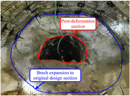
(1) Comprehensive Deformation: The entire cross-section of the roadway undergoes substantial deformation to varying degrees, with the bottom region exhibiting the most pronounced deformation. Notably, the maximum sectional contraction and deformation attain a magnitude of 1.5 m–2 m, as evident in Figure 2, underscoring the pervasive and significant nature of this deformation across all parts of the roadway.
(2) Material-Specific Deformation Patterns: The mudstone and sandy mudstone sections of the roadway exhibit a predominance of full-section extensional deformation, characterized by the expansion of the rock mass across the entire cross-section. In contrast, the siltstone and fine sandstone sections are governed by deformation mechanisms primarily associated with shear fractures, highlighting the material-dependent variability in deformation modes within the roadway.
(3) Rheological Behavior: The deformation of the roadway’s peripheral rock demonstrates a progressive increase over time, exhibiting pronounced rheological properties. This time-dependent deformation underscores the need for innovative support strategies that can effectively address the dynamic nature of the surrounding rock mass.
3.2 Analysis of the causes of lane deformation
3.2.1 Physical and mechanical properties of the surrounding rock
The inferior strength of the surrounding rock mass, coupled with its propensity for substantial expansion upon water exposure, constitutes the primary factors contributing to the extensive deformation observed in the roadway. To elucidate the geological underpinnings, the upper and lower strata of the tunnel under investigation were sampled, primarily comprising carbonaceous mudstone and siltstone. These samples underwent rigorous analysis via Scanning Electron Microscopy (SEM) observation and X-ray Diffraction (XRD) techniques. The findings reveal a complex mineralogical composition within the mudstone and sandstone, with clay minerals (encompassing water mica, kaolinite, and pearl clay, among others) occupying a prominent position, followed by detrital minerals such as quartz, feldspar, and mica, in addition to ferromanganese and organic constituents. The scanned samples exhibit a loose texture, marked by poor consolidation and negligible recrystallization phenomena, as visually discernible in Figure 3. Notably, the analyzed rocks display elevated concentrations of quartz, kaolinite, and dolomite—key components known to elicit swelling and deformation in soft rocks upon hydration. Furthermore, Table 1 compiles the mechanical parameters derived from uniaxial and triaxial rock mechanics tests conducted on core samples sourced from various lithological units (Li et al., 2023; Li et al., 2024). These parameters offer crucial insights into the mechanical behavior of the rocks, facilitating a more comprehensive understanding of the deformation mechanisms at play within the roadway.
3.2.2 High tectonic stresses at the project site
The main cause of significant deformation in the roadway system originates from heightened tectonic stress conditions. The predominant mining coal seams at the Yindonggou mine display a remarkably stable inter-seam spacing. The first and second coal seams are separated by an average distance of 8.42 m. Similarly, the spacing between the fourth and second coal seams remains relatively stable. The upper distance varies from 17.89 to 40.10 m. Additionally, the vertical separation between the fifth and fourth coal seams ranges narrowly from 0.80 to 12.26 m and averages 8.38 m, highlighting the characteristic proximity of coal seams as shown in Figure 4. The prevailing mining coal seams at the Yindonggou mine exhibit a notably stable inter-seam spacing, with the 1st and 2nd coal seams separated by an average distance of 8.42 m. The predominant mining coal seams at the Yindonggou mine display The primary roadway network is subjected to the combined influence of the Yindonggou syncline and anticline, culminating in a complex tectonic stress environment. Notably, the extraction of a protective layer within a closely spaced coal seam group, in contrast to single seam mining, triggers a profound redistribution of stresses within the coal-rock matrix, fostering mutual stress perturbations and a dynamically evolving stress field in localized regions (Gong and Guo, 2018; An and Cheng, 2014).

Figure 4. The schematic diagram of typical close distance coal seam and roadway strata section in 11 mining area.
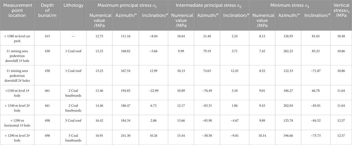
The drilling stress relief methodology was employed to assess the geostress at thirty distinct locations within the roadway system of the Yindonggou mine, with a focus on seven test points strategically positioned adjacent to the horizontal pedestrian downhill roadway spanning from +1380 m to +1290 m in the 11th mining zone. The outcomes of these tests are comprehensively documented in Table 2. The maximum principal stress is 16.91 MPa; its direction tends to be horizontal, and the angle of inclination with the axis of the roadway is −23°∼10°, and the lateral pressure coefficient is about 1.21∼1.35. In addition, the stability of the surrounding rock of the roadway is obviously affected by the horizontal tectonic stress.
Upon tunnel excavation, the radial direction, perpendicular to the tunnel axis, undergoes a state of decompression, whereas the tangential direction along the perimeter experiences a state of stress augmentation. This bidirectional stress variation inevitably subjects the surrounding rock mass to substantial deviatoric stress. According to elasticity theory analyses, the peak stress surrounding the tunnel can escalate to twice the magnitude of the virgin rock stress, exceeding the strength threshold of siltstone. Consequently, following excavation, fractures within the surrounding rock propagate rapidly and extensively from the exposed surface towards the interior, underscoring the pronounced contradiction between the elevated stress levels and the relatively low strength characteristics of the surrounding rock.
3.2.3 Inadequate perimeter rock support
To ensure the stability of soft rock formations under elevated tectonic stresses, providing adequate support strength is essential. Current practices for supporting soft rock roadways in such conditions mainly rely on anchor rods, anchor cables, and similar reinforcement techniques, frequently neglecting direct support for the invert. When faced with significant horizontal compressive forces, the invert plays a crucial role in stress dissipation, subsequently affecting the integrity of both ribs and roof, resulting in substantial deformations across the entire cross-section. Consequently, an optimized reinforcement strategy that addresses the invert’s vulnerability is crucial for reducing such deformations and maintaining overall structural stability in the geological context of high tectonic stresses.
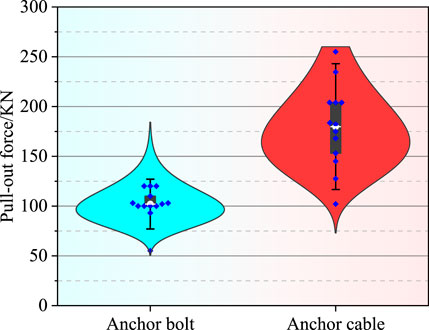
Typically, achieving a pullout force exceeding the stringent support resistance threshold of 200 kN for anchor rods and cables embedded within fractured coal-rock masses poses a significant challenge. An illustrative analysis of pullout tests conducted on select anchor rods and cables within the Yindonggou region, as depicted in Figure 5, reveals intriguing insights. Notably, the pullout forces exhibited by anchor rods display a relatively narrow distribution, with a remarkable 12 out of 13 tests yielding loads surpassing 90 kN. In contrast, the pullout performance of anchor cables is more variable, spanning a broader range from 102 to 255 kN across 14 tests. This suggests that the damage and deterioration of the surrounding rock are more severe, which will influence the anchoring efficacy of anchor rods and anchor cables. In case there are additional microcracks and pores in the surrounding rock, local stress concentration may arise in the anchor cable during the stressing process, leading to a reduction in anchorage force. Regarding anchor rods, due to their relatively short length, they are less susceptible to the damage and deterioration of the surrounding rock. Moreover, the dispersion of the pullout force experiment results is relatively minor.
A comprehensive 45-day assessment of the operational anchorage forces of anchor rods and cables was undertaken, and the outcomes are presented in Figure 6. Within the context of the soft and fractured coal-rock strata, an alarming trend was observed where the initial anchorage forces of approximately 90% of the anchor rods and cables swiftly diminished to levels beneath 20 kN, compromising the efficacy of the intended prestressed support system. Subsequent meticulous analysis illuminated that over 80% of the anchor rods exhibited a marked stability in their anchorage forces over time, while anchor cables displayed a pronounced variability in this regard. This dichotomy underscores the complexity of the loosening zones encountered within the peripheral rock mass of the Yindonggou mine, with anchor cables playing a pivotal role in modulating the deformation of deeper, less consolidated strata, thereby necessitating tailored reinforcement strategies to ensure long-term structural integrity.
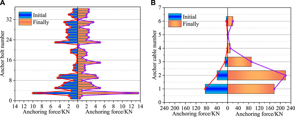
Figure 6. Comparison of initial and final anchoring force of anchor bolt and anchor cable support. (A) Anchoring force of anchor bolt. (B) Anchoring force of anchor cable.
4 Repair measures for large deformation roadway based on the theory of surrounding rock instability
4.1 Theory of surrounding rock instability
Utilizing the fundamental principles of the classical Mohr-Coulomb criterion, Figure 7 serves as a platform to illustrate the intricate interplay between alterations in stress states and the stability of the surrounding rock matrix, both preceding and subsequent to excavation operations. Prior to excavation, the tunnel resides within the native rock stress regime, where the maximum principal stress (σn0) and minimum principal stress (σt0) on the refuge wall’s surface exhibit a close proximity. At a depth of +1,290 m, for instance, these stresses are recorded as σt0 = 10.7 MPa and σn0 = 16.9 MPa, respectively. Consequently, the diameter of Mohr’s circle, embodying the deviatoric stress state, attains its minimal dimension (coinciding with the minimum under uniform pressure conditions), and remains distant from the strength envelope L1 of the enclosing rock mass (as depicted in Figure 7). This spatial segregation signifies that the surrounding rock is in a state of stability (Lee et al., 2014; Tsoi and Usol Tseva, 2019).
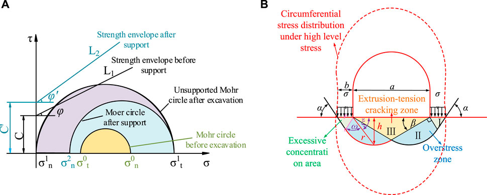
Figure 7. The stress state of surrounding rock before and after excavation and support of high level stress roadway. (A) The change of surrounding rock strength envelope before and after excavation and support. (B) The stress distribution state of surrounding rock after excavation.
Upon completion of the roadway excavation, a distinct stress redistribution was observed, with the normal stress (σn1) at the refuge wall’s surface diminishing to zero, while the circumferential stress (σtl) augmented. Utilizing the siltstone strata at the tunnel crown as a case study, elastic stress analysis indicates that σtl = 2σn0 = 33.8 MPa, exceeding the uniaxial compressive strength threshold. Consequently, the Moore circle transcends the strength envelope L1 of the perimeter rock, initiating shear failure within the rock mass (Han et al., 2020). As depicted in Figure 7B, the elevated stress levels encountered in the Yindonggou mine initially manifested as deformation within the inadequately supported bottom strata, accompanied by the extrusion of tension-induced fractures and the emergence of initial bottom sagging cracks. Subsequently, these were followed by pronounced bottom sagging, triggered by the compressive crushing and instability of the two gangs located at the bottom corners within the stress concentration zone of the surrounding rock. Ultimately, these phenomena culminated in the uncontrollable deformation and contraction of the entire tunnel section, highlighting the complex interplay of stress, strain, and stability in underground excavations. Therefore, to ensure the stability of the roadway, the foremost imperative lies in swiftly restoring and enhancing the stress state of the surrounding rock post-excavation. This entails transforming the two-way stress state, a byproduct of stress field adjustments following excavation, back to a three-way stress state, aiming to partially restore the minimum principal stress to σn2, acknowledging the inherent challenges in achieving full restoration. The timeliness of these stress-restoration measures is paramount, as it directly correlates with mitigating the extent of fracturing and dilation in the surrounding rock, thereby preserving its integrity and fostering stability. Additionally, the reinstatement of higher compressive stress on the refuge wall’s surface augments the rock’s strength, self-bearing capacity, and overall stability. Consequently, prompt and adequate support for the tunnel upon excavation is vital, with the support system designed to withstand sufficient resistance.
Based on the initial anchor rod and anchor cable support parameters, along with anchoring force test results obtained from Yindonggou Mine, it is evident that the idealized conversion of support resistance to σn2 = 0.36 MPa poses a significant challenge in achieving effective stress recovery. This modest value underscores the inherent difficulty in restoring the desired stress state. Furthermore, an excessively high preload can induce microstructural fractures and misalignment within the support system, which represents a pivotal factor contributing to the persistent development of shear deformations and the radial expansion of the loosening zone from the excavation surface towards the interior.
4.2 Support strategies for controlling large deformations in soft rock roadways
Based on a rigorous analysis of peripheral rock deformation mechanisms and instability theories, the subsequent paper proposes the following strategies for enhancing peripheral rock stability within the repaired large deformation roadway of the pedestrian downhill section in the 11th mining area:
(1) In regions where the top and bottom slabs predominantly consist of siltstone, high-strength anchor cables are employed to impart substantial support resistance. This approach augments the rigidity of anchored surface components and refines the adjustment capabilities of the anchoring system, thereby ensuring effective dissipation of high pre-stress levels. Consequently, the triaxial stress state of the surrounding rock is reinstated, harnessing its inherent self-supporting capabilities to the fullest extent.
(2) For the upper and lower slabs characterized by carbonaceous mudstone and expansive soft rock, a synergistic reinforcement scheme is devised. This entails utilizing anchor rods and cables to apply a judicious initial prestress, complemented by U-shaped steel brackets for coordinated support. This composite reinforcement strategy significantly enhances the stiffness of the roadway wall support, mitigating deformation tendencies.
(3) In the aftermath of extensive deformation, the presence of pervasive cracks in the compromised peripheral rock necessitates an advanced stabilization methodology. To address this, supplementary hollow grouting anchor rods and cables are strategically installed. The integration of anchoring and grouting techniques fortifies the surrounding rock mass, enabling the application of heightened support resistance while consolidating the fractured rock matrix.
(4) To provide a holistic support framework, an additional base plate support structure is incorporated. This comprehensive reinforcement measure ensures that the repaired roadway is adequately braced against further deformation, safeguarding both structural integrity and operational safety.
4.3 Key technology to control large deformation of soft rock roadway
4.3.1 Optimal anchorage prestressing
The resin-bonded anchorage interface serves as a pivotal mechanical interface, facilitating the efficient transmission of shear stresses between the anchor cable and the surrounding rock matrix. The distribution patterns of these shear stresses, under varying tensile loads in an idealized anchorage scenario, are delineated in Figure 8, encompassing five distinct states that illuminate the interplay between anchorage and rock response:
1) Low Tensile State: At the onset of tension, the shear stress magnitudes proximate to the anchorage section’s inception are prominent, albeit significantly inferior to the interface’s shear strength threshold (τ1). This region of the surrounding rock experiences the most intense stress concentration.
2) Elastic Pull-out Limit: As the tensile force nears the elastic limit for pull-out, the shear stress values adjacent to the anchorage’s inception verge on the interface’s shear strength (τ1), signifying a critical transition point.
3) Pull-out Displacement Regime: Upon achieving the interface’s shear strength (τ1) at the initial segment of the anchor cable anchorage, shear slip initiates, resulting in a gradual degradation of the interface strength to its residual bond strength (τ2). Frictional forces subsequently dominate the mechanical response.
4) Maximum Tension State: In this ultimate state, the peak shear stress at the anchorage interface propagates to the midpoint of the anchorage section, as evidenced by the shear stress profile encircling the largest area along the cable’s length (integral of shear stress along cable length equals axial tension). This signifies the attainment of peak pull-out force, with the most extensive influence on the surrounding rock matrix.
5) Residual Pull-out Strength State: In this phase, the peak shear strength at the anchor cable’s anchorage interface propagates deeper into the rock matrix at an accelerated rate. Concurrently, the shear stress profile and the area encompassed by the cable axis undergo a gradual reduction. As the anchorage interface transitions to its residual bond strength (τ2), the pull-out force experiences a rapid decline in dominance. Consequently, the anchor cable is expelled from the rock in a markedly abbreviated timeframe, marking the culmination of the pull-out process.
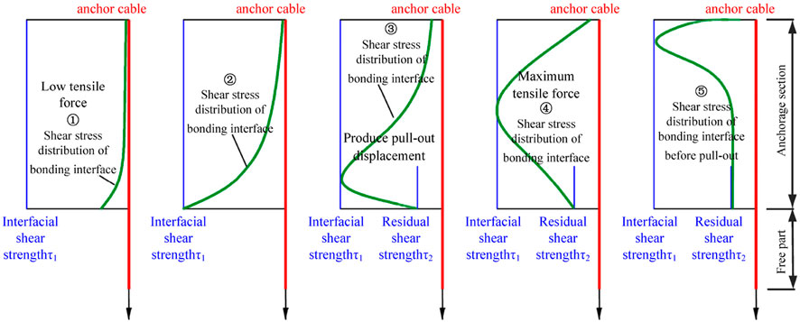
Figure 8. The shear stress distribution state of anchorage interface during the drawing process of anchor bolt and anchor cable.
The on-site tensile evaluation of anchor reinforcement in the expansive soft rock tunnels of Yindonggou mine shows a remarkable performance. Approximately 90% of the anchor rods reach a peak tensile capacity exceeding 90 kN, and around 80% of anchor cables attain a maximum tension greater than 125 kN. Considering the established design parameters of these anchor systems, the optimal range for anchor rod prestressing is defined between 80 and 90 kN. For anchor cables, it is within 120–160 kN. In expansive soft rock environments, excessive prestressing of anchors can lead to localized debonding phenomena and cause anchor failure, presenting challenges in maintaining the stability of the surrounding rock mass and requiring meticulous control measures.
4.3.2 U-type steel bracket wall fillings
1) To ensure uniform stress distribution within the U-shaped steel ribs, the incorporation of high-strength backing plates and meticulous wall backfilling practices is paramount. This approach ensures that the ribs are subjected to balanced loads, optimizing their structural integrity.
2) Recognizing the distinct pressure profiles exerted by the surrounding rock strata in tunnel environments, tailored reinforcement strategies involving local anchor rods and cables are implemented. These elements strategically target vulnerable zones of the U-shaped ribs, enhancing their restraint capabilities and thereby augmenting overall system stability. In scenarios characterized by pronounced horizontal stress, the legs of the rib structure, being pivotal points, undergo additional reinforcement with anchor cable tie beams. This coordinated support framework effectively mitigates deformation, particularly within the critical two-legged segments.
3) To rigorously manage deformation at the base corners, where the stability of the U-shaped ribs is most susceptible, high-strength bottom-angle anchors are strategically deployed. These anchors act as robust safeguards, preventing the premature destabilization and subsequent rapid loss of bearing capacity at the base corners, thereby preserving the overall structural integrity and longevity of the ribbed support system.
4.3.3 Comprehensive grouting strategy for fractured peripheral rock in high deformation tunnels
1) A hybrid grouting approach, integrating both deep and shallow hole techniques, is advocated for reinforcing fractured peripheral rock in tunnels experiencing significant deformation. Initially, shallow holes are subjected to low-pressure grouting, while progressively increasing the pressure in deep holes ensures deeper penetration and enhanced reinforcement of the surrounding rock matrix. This stratified approach maximizes the effectiveness of grouting in mitigating deformation.
2) The grouting slurry employed comprises a single-liquid cementitious blend, utilizing P.O 42.5R ordinary Portland cement as its primary constituent. The water-cement ratio of this slurry is meticulously calibrated within the range of 1:0.7 to 1:1, ensuring optimal workability and hardening properties essential for effective rock consolidation.
3) Through rigorous monitoring of tunnel deformation, the temporal and spatial patterns of surrounding rock movement are elucidated. This deformation analysis serves as a pivotal input for informed decision-making regarding the timing and extent of localized reinforcement and anchoring replenishment measures. By leveraging deformation data, targeted interventions can be implemented, thereby optimizing tunnel stability and mitigating the risk of premature failure.
5 Specific support scheme and effect analysis for controlling large deformation of soft rock roadway
5.1 Specific support scheme for controlling large deformations of soft rock roadways
In conjunction with the support strategy elaborated in Section 4.2, the pedestrian descent route within Mining Area 11 was strategically segmented into two distinct zones, each tailored to the unique lithological characteristics encountered. A differentiated support scheme was subsequently devised, as detailed in the following paragraphs.
1) The descent ramp segment spanning from +1,380 m to +1,340 m depth is characterized by the presence of highly compressible geological formations, notably carbonaceous clay and coal seams, which have undergone significant disturbance due to recurrent reworking activities. Consequently, an exceptionally robust support system was devised. This comprises a pre-stressed anchor cable system, a full-circumference U-shaped steel ribbing, and a post-installed concrete backfill wall reinforcement. The key param of this system are specified as follows:
① The anchor design employs Φ22 × 2,500 mm anchors with a minimum preload force of 80 kN, arranged in a grid pattern with a spacing of 1,500 mm between rows and 800 mm between columns.
② The anchor cable system utilizes Φ21.6 × 6,200 mm cables, deployed in a full-section configuration. These cables are subjected to a preload force not less than 120 kN, with a spacing of 1,000 mm between rows and 800 mm between columns.
③ To further fortify this section, a mesh reinforcement layer is applied and overlaid with shotcrete, applied in two layers: an initial layer of 50 mm thickness, followed by a final layer of 150 mm, both with a compressive strength of C20.
④ The U-shaped steel ribbing and filling methodology involves the installation of U29-3.6 m full-circumference steel sheds spaced at 800 mm intervals. Thin wooden boards are strategically positioned behind the sheds, serving as formwork for the subsequent pouring of C30 grade concrete with a thickness ranging from 400 to 500 mm, effectively filling the void.
⑤ Lastly, the concrete floor is constructed with a thickness of 520 mm and a compressive strength of C30, ensuring structural integrity and durability under the anticipated loads and conditions.
2) The downhill inclined alley segment spanning from an elevation of +1,340 m to +1,290 m is predominantly characterized by the outcropping of siltstone, locally interstratified with carbonaceous mudstone and coal seams. To mitigate geological challenges and ensure structural integrity, this section is engineered to be supported by a comprehensive system incorporating full-section pre-stressed conventional anchor cables and hollow grouting anchor cables. The specific design param are detailed as follows:
① The anchor rods employed consist of Φ22 × 2,500 mm left-handed, non-longitudinal ribbed threaded steel, designed to withstand an anchor preload not less than 90 kN. These rods are strategically positioned with an inter-row spacing of 1,500 mm horizontally and 800 mm vertically, optimizing their effectiveness in reinforcing the slope.
② The anchor cable system features Φ21.6 × 6,200 mm cables arranged in a full-section configuration. Each cable is securely connected to a steel beam integrated into the bottom plate, ensuring efficient load transfer and system integrity. The anchor cables are subjected to a preload force not less than 160 kN, with an inter-row spacing of 1,000 mm horizontally and 800 mm vertically, providing robust reinforcement.
③ The entire alley section is further strengthened by the installation of a hanging reinforcing steel mesh and the application of sprayed concrete slurry. The sprayed concrete, boasting a compressive strength of C20, is applied in two layers: an initial layer of 50 mm thickness, followed by a reinforcing layer of 150 mm thickness, significantly enhancing the durability and resistance to erosion.
④ The hollow grouting anchor cable system utilizes Φ22 × 6,300 mm cables, positioned with a row spacing of 1,600 mm in both horizontal and vertical directions. Grouting is performed using P.O 42.5 R ordinary silicate cement, aiming to achieve a final hole pressure of 3 MPa. However, in the event of grout leakage, the grouting operation is halted as per specified protocols, ensuring the safety and efficacy of the reinforcement measures.
⑤ Lastly, a concrete floor with a thickness of 520 mm and a compressive strength of C30 is poured, providing a stable and durable foundation for the entire downhill inclined alley segment. This design approach ensures that the structural integrity and safety of the slope are maintained, even under challenging geological conditions.
5.2 Effect analysis for controlling large deformation of soft rock roadway
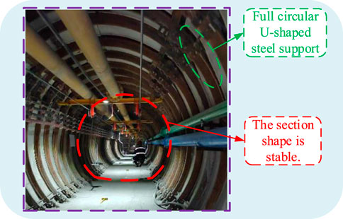
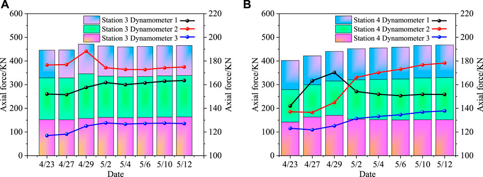
After the successful completion of the pedestrian downhill roadway construction, a comprehensive five-month-long long-term deformation monitoring program was commenced to evaluate the roadway’s convergence deformation and anchor cable force performance. The results show that the roadway section has excellent geometry and effectively maintains the stability of the surrounding rock mass. Specifically, in the monitored section of the pedestrian downhill roadway in the 11th mining area, the maximum recorded arch deformation was 182 mm, and the floor deformation was 265 mm. Notably, through targeted reinforcement of anchor cables and localized grouting measures, the sectional deformation has been reduced to less than 10 mm over the past 3 months, highlighting the effectiveness of the implemented strategies. The practical results are visually presented in Figure 9. Subsequent to the pavement repairs, two representative sections were randomly selected for further analysis. Within each section, an anchor cable from the left and right rib walls, as well as the overhead slab, was sampled for force monitoring, as depicted in Figure 10. The initial anchorage forces of all sampled anchor cables surpassed 116 kN, indicating robust initial performance. Additionally, the anchorage force of the anchor cables responded dynamically to the deformation of the surrounding rock, primarily exhibiting an increasing trend. This increase was predominantly concentrated within the initial 10 days, thereafter tapering off and gradually stabilizing, indicating a successful adaptation and reinforcement of the roadway’s structural integrity.
6 Discussion
Given the complex geological conditions, high tectonic stress, and unique characteristics of the surrounding rock in the pedestrian downhill project of the 11th mining area of Yindonggou Mine, this study relies on the engineering conditions and the findings of research in related fields to guide its approach (Shan et al., 2022; Yang X. et al., 2023; Xu et al., 2022). A variety of support schemes have been put forward to deal with the diverse characteristics of the surrounding rock, and the support effects of these support schemes have been strictly examined.
1) Considering the relatively intact soft rock roadway, this study adopts a support scheme consisting of high pre-stressed bolts, anchor cables, and shotcrete.
2) Taking into account the high ground stress detected in the soft rock roadway, this study makes use of a support scheme including high pre-stressed anchor cables, shotcrete, and ground grouting anchor cables.
3) Due to the fractured surrounding rock roadway, this study employs the support scheme of high prestressing anchor + anchor cable + shotcrete + ground injection anchor cable + combined support of deep and shallow injection.
4) Considering the repeated disturbance of soft rock roadway, this study uses an active + passive support coupling support system. Active support: high prestressed anchor cable + shotcrete + floor grouting anchor cable. Passive support: erecting U-shaped shed frame + high rigid steel mesh back plate and filling graded gravel after the back plate. Coupling support: deep and shallow grouting at the top of the side.
5) Given the special geological section support for high stress extremely soft rock, this study employs the temporary support + permanent support coupling support system. The section is designed as a full circular section. Temporary support: high prestressed anchor cable + shotcrete + floor grouting anchor cable. Permanent support: double row steel bar + pouring concrete + U-shaped steel frame. Coupling support: full section wall post grouting.
6) Considering the special geological section support for high stress extremely soft rock, this study uses high prestress group anchor support + π type steel beam and single hydraulic prop combined support. The construction sequence is: excavation → hanging net, bolt (anchor cable) support → secondary fastening → π type steel beam and single hydraulic prop combined support.
Due to space limitations, this study only chose the plastic zone and vertical displacement as the evaluation indexes of the support effect. As shown in Table 3, regardless of the surrounding rock conditions, the expansion of the plastic zone is effectively restricted within the protection range provided by the support system. Notably, the maximum vertical displacement of the repeatedly disturbed soft rock roadway and the extensive soft rock stratum is 1.6 mm and 6 mm respectively. In contrast, the maximum vertical displacement in other surrounding rock conditions is kept at a level below 1 mm. The data show that the stability of the surrounding rock is effectively controlled under the differentiated support scheme, thus verifying the feasibility and effectiveness of each support scheme. The construction technology and support scheme put forward in this study are intended to provide valuable references and inspiration for similar projects. However, it should be noted that in the face of repeated disturbances of soft rock roadways and large-section soft rock strata, especially the extremely harsh geological conditions at the bottom of large-section soft rock, the design and selection of support schemes should be more cautious and scientific to ensure the safety and long-term stability of the project.
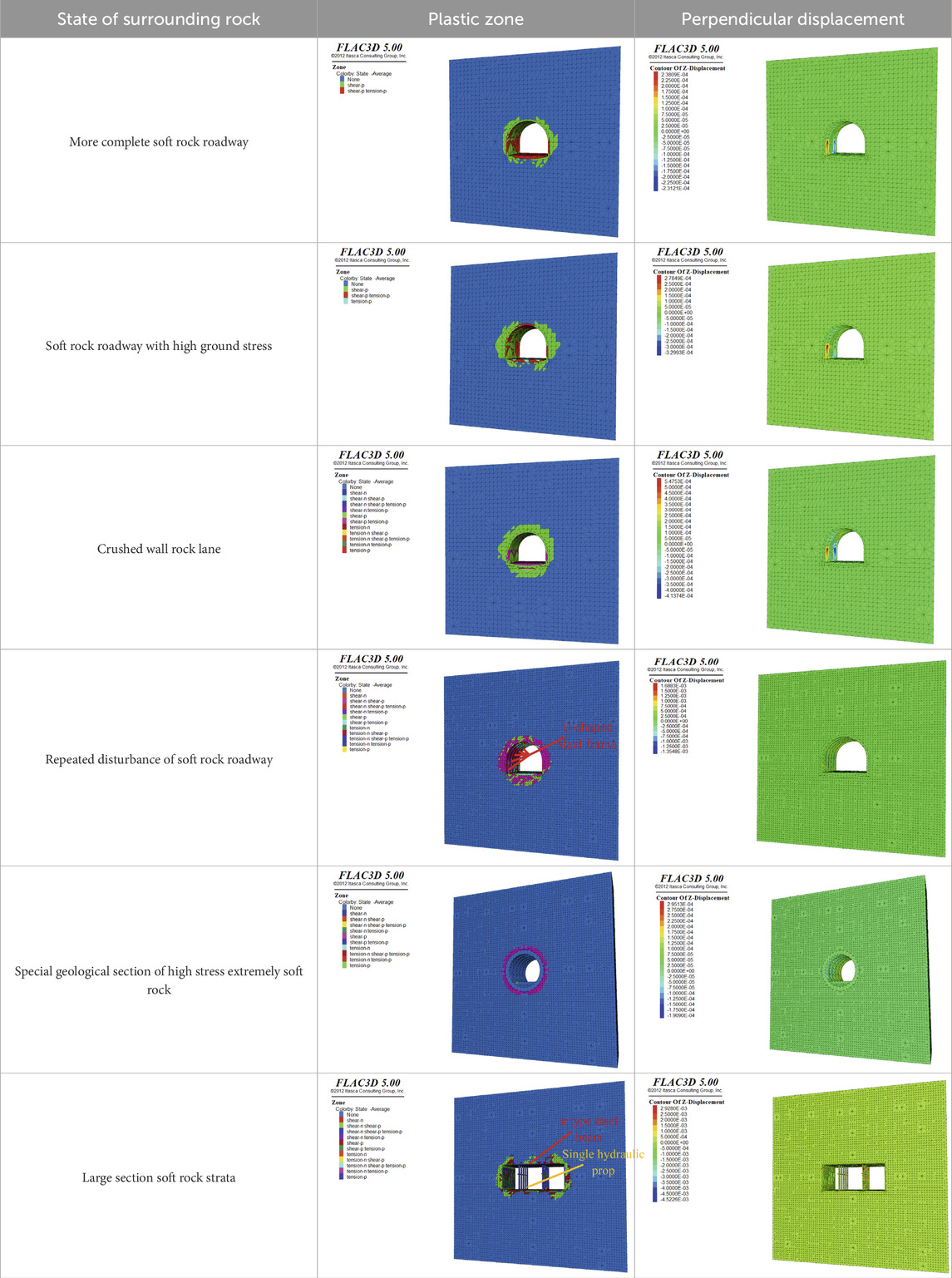
Table 3. Comparison of supporting effects of different supporting methods under different surrounding rock conditions.
7 Conclusion
In this research, we elucidate the intricate mechanisms underlying the extensive deformation and instability of the pedestrian roadway within the 11th mining area of the Yindonggou mine by considering the multifaceted influences of surrounding rock lithology, geological structures, and employed support measures. Based on this comprehensive analysis, we formulate a strategic blend of roadway rehabilitation measures and control strategies grounded in the principles of surrounding rock instability theory. The efficacy of these interventions is rigorously validated through field applications, yielding the following insights:
(1) The coexistence of expansive soft rock with fractured sections, coupled with their inherent high strength dispersion and inadequate support resistance, is identified as a pivotal factor for the pronounced deformation observed in the soft rock roadways of the Yindonggou mine.
(2) The primary factor driving roadway deformation disasters in the Yindonggou mine results from the combined effects of high tectonic stress within the strata and the weakened strength of the surrounding rock, exacerbated by the disruptive influence of adjacent coal seam mining activities. This heightened stress environment initially triggers deformation in the inadequately supported floor, subsequently propagating and exacerbating the deformation and instability of the adjacent rock masses, ultimately leading to the collapse of the entire roadway section.
(3) The design of soft rock support systems must be tailored to the specific rock properties and tectonic stress regime of the surrounding geological formations. In roadways where the roof and floor are primarily composed of carbonaceous mudstone and expansive soft rock, the support strategy focuses on enhancing the rigidity of the roadway walls. This involves the application of initial prestressing to anchor cables, coupled with the reinforcement of U-shaped steel bracketing systems fortified with high-strength backfill materials to ensure coordinated support. Conversely, in roadways characterized by siltstone-dominated roof and floor formations, the emphasis shifts towards restoring the triaxial stress state of the surrounding rock to optimize its inherent self-supporting capabilities. This approach necessitates deploying high-resistance anchor cables and implementing grouting techniques to repair and strengthen the surrounding rock matrix.
(4) Based on the engineering conditions of the pedestrian downhill in the 11th mining area of Yindonggou Mine, diverse support schemes are put forward for different surrounding rock conditions, and the actual effects of these support schemes are thoroughly explored. The simulation results indicate that the stability of the surrounding rock is effectively controlled under the differentiated support scheme, thereby verifying the feasibility and effectiveness of each support scheme.
Data availability statement
The raw data supporting the conclusions of this article will be made available by the authors, without undue reservation.
Author contributions
ML: Writing–review and editing, Data curation, Funding acquisition. LY: Writing–review and editing, Formal Analysis. JF: Data curation, Writing–original draft. YF: Writing–review and editing. HW: Writing–review and editing. XW: Writing–review and editing, Data curation.
Funding
The author(s) declare that financial support was received for the research, authorship, and/or publication of this article. This work is financially supported by Scientific Research Project of Colleges and Universities in Anhui Province (Natural and Science) (no. 2022AH050815). The authors gratefully acknowledge financial support of the abovementioned agencies.
Conflict of interest
Authors LY, YF, HW, and XW were employed by Ningxia Wangwa Coal Industry Co. Ltd.
The remaining authors declare that the research was conducted in the absence of any commercial or financial relationships that could be construed as a potential conflict of interest.
Publisher’s note
All claims expressed in this article are solely those of the authors and do not necessarily represent those of their affiliated organizations, or those of the publisher, the editors and the reviewers. Any product that may be evaluated in this article, or claim that may be made by its manufacturer, is not guaranteed or endorsed by the publisher.
References
Alejano, L. R., Rodríguez-Dono, A., and Veiga, M. (2012). Plastic radii and longitudinal deformation profiles of tunnels excavated in strain-softening rock masses. Tunn. Undergr. Space Technol. 30, 169–182. doi:10.1016/j.tust.2012.02.017
An, F., and Cheng, Y. (2014). The effect of a tectonic stress field on coal and gas outbursts. Sci. World J. 2014, 1–10. doi:10.1155/2014/813063
Basarir, H., Sun, Y., and Guichen, L. (2019). Gateway stability analysis by global-local modeling approach. Int. J. Rock Mech. Min. 113, 31–40. doi:10.1016/j.ijrmms.2018.11.010
Fa-you, A., Dai, X. G., Zhang, P., Hei, M. C., and Yan, S. Q. (2022). Experimental investigation of the influence of the anchor cable inclination angle on the seismic response characteristics of anchored piles. Geofluids 2022, 1–13. doi:10.1155/2022/9167573
Gong, W., and Guo, D. (2018). Control of the tectonic stress field on coal and gas outburst. Appl. Ecol. Env. Res. 16 (6), 7413–7433. doi:10.15666/aeer/1606_74137433
Guo, S., Zhu, X., Liu, X., Duan, H., Jia, L., and Lin, J. (2021). A case study of optimization and application of Soft-Rock roadway support in xiaokang coal mine, China. Adv. Civ. Eng. 2021, 1–14. doi:10.1155/2021/3731124
Guo, T., Kang, H., Wang, L., Liu, Q., and Zhao, Y. (2018). Modal resonant dynamics of cables with a flexible support: a modulated diffraction problem. Mech. Syst. Signal. Pr. 106, 229–248. doi:10.1016/j.ymssp.2017.12.023
Guo, T., Kang, H., Wang, L., and Zhao, Y. (2017). An asymptotic expansion of cable–flexible support coupled nonlinear vibrations using boundary modulations. Nonlinear Dynam 88 (1), 33–59. doi:10.1007/s11071-016-3229-8
Han, G., Jing, H., Jiang, Y., Liu, R., and Wu, J. (2020). Effect of cyclic loading on the shear behaviours of both unfilled and infilled rough rock joints under constant normal stiffness conditions. Rock Mech. Rock Eng. 53, 31–57. doi:10.1007/s00603-019-01866-w
Kang, H. P., Yang, J. W., Jiang, P. F., Gao, F. Q., Li, W. Z., Li, J. F., et al. (2024a). Theory, technology and application of grouted bolting in soft rock roadways of deep coal mines. Int. J. Min. Mater. Mat. 31 (7), 1463–1479. doi:10.1007/s12613-024-2906-8
Kang, H. P., Yuan, G. Y., Si, L. P., Gao, F. Q., Lou, J. F., Yang, J. H., et al. (2024b). Mechanical behavior and failure mechanisms of rock bolts subjected to static-dynamic loads. Int. J. Min. Sci. Techno. 34 (3), 281–288. doi:10.1016/j.ijmst.2024.02.007
Lee, J. Y., Ryu, H. R., and Park, Y. T. (2014). Finite element implementation for computer-aided education of structural mechanics: Mohr's circle and its practical use. Comput. Appl. Eng. Educ. 22 (3), 494–508. doi:10.1002/cae.20575
Li, J. (2024). Analysis of stability in pedestrian downhill roadway at Yindonggou 11th coal mine area: the impact of anchor cable support density. Front. Energy Res. 12, 1347795. doi:10.3389/fenrg.2024.1347795
Li, Y. M., Li, J. L., Wu, Y. H., and Zhao, G. F. (2024). Extracting rock parameters through digital drilling test. Rock Mech. Rock Eng. 57, 8215–8241. doi:10.1007/s00603-024-03951-1
Li, Y. M., Zhao, G. F., Jiao, Y., Yan, C., Wang, X., Shen, L., et al. (2023). A benchmark study of different numerical methods for predicting rock failure. Int. J. Min. Sci. Techno 166, 105381. doi:10.1016/j.ijrmms.2023.105381
Martino, J. B., and Chandler, N. A. (2004). Excavation-induced damage studies at the underground research laboratory. Int. J. Rock Mech. Min. Sci. 41 (8), 1413–1426. doi:10.1016/j.ijrmms.2004.09.010
Meng, N., Bai, J., and Yoo, C. (2023). Failure mechanism and control technology of deep soft-rock roadways: numerical simulation and field study. Undergr. Space 12, 1–17. doi:10.1016/j.undsp.2023.02.002
Shan, R., Huang, P., Yuan, H., Meng, C., and Zhang, S. (2022). Research on the full-section anchor cable and C-shaped tube support system of mining roadway in island coal faces. J. Asian Archit. Build. 21 (2), 298–310. doi:10.1080/13467581.2020.1869556
Shi, H., Chen, W., Zhang, H., and Song, L. (2023a). A novel obtaining method and mesoscopic mechanism of pseudo-shear strength parameter evolution of sandstone. Environ. Earth Sci. 82 (2), 60. doi:10.1007/s12665-023-10748-y
Shi, H., Chen, W., Zhang, H., Song, L., Li, M., Wang, M., et al. (2023b). Dynamic strength characteristics of fractured rock mass. Eng. Fract. Mech. 292, 109678. doi:10.1016/j.engfracmech.2023.109678
Shi, H., Song, L., Zhang, H., Chen, W., Lin, H., Li, D., et al. (2022). Experimental and numerical studies on progressive debonding of grouted rock bolts. Int. J. Min. Sci. Techno. 32 (1), 63–74. doi:10.1016/j.ijmst.2021.10.002
Shi, H., Zhang, H. Q., Song, L., and Wu, Y. (2019). Variation of strata pressure and axial bolt load at a coal mine face under the effect of a fault. Arch. Min. Sci. 64 (2), 351–374. doi:10.24425/ams.2019.128688
Tsoi, P. A., and Usol Tseva, O. M. (2019). Use of mohr’s circles for connection and model estimation of strength data of Different-Size rock samples. J. Min. Sci+ 55 (2), 194–200. doi:10.1134/S1062739119025456
Varas, F., Alonso, E., Alejano, L. R., and Manín, G. F. (2005). Study of bifurcation in the problem of unloading a circular excavation in a strain-softening material. Tunn. Undergr. Space Technol. 20 (4), 311–322. doi:10.1016/j.tust.2004.12.003
Wang, Q., Ye, H., Li, N., Chi, X., Xie, W., Chen, D., et al. (2021). A study of support characteristics of collaborative reinforce system of U-Steel support and anchored cable for roadway under high dynamic stress. Geofluids 2021, 1–12. doi:10.1155/2021/9881280
Wu, J., Jing, H., Gao, Y., Meng, Q., Yin, Q., and Du, Y. (2022). Effects of carbon nanotube dosage and aggregate size distribution on mechanical property and microstructure of cemented rockfill. Cem. Concr. Comp. 127, 104408. doi:10.1016/j.cemconcomp.2022.104408
Wu, J., Jing, H., Yin, Q., Yu, L., Meng, B., and Li, S. (2020). Strength prediction model considering material, ultrasonic and stress of cemented waste rock backfill for recycling gangue. J. Clean. Prod. 276, 123189. doi:10.1016/j.jclepro.2020.123189
Wu, J., Wong, H. S., Zhang, H., Yin, Q., Jing, H., and Ma, D. (2024). Improvement of cemented rockfill by premixing low-alkalinity activator and fly ash for recycling gangue and partially replacing cement. Cem. Concr. Comp. 145, 105345. doi:10.1016/j.cemconcomp.2023.105345
Xu, D., Gao, M., and Yu, X. (2022). Dynamic response characteristics of roadway surrounding rock and the support system and rock burst prevention technology for coal mines. Energies 15 (22), 8662. doi:10.3390/en15228662
Yang, X., Ming, W., Gong, W., Pan, Y., He, M., and Tao, Z. (2023b). Support characteristics of flexible negative Poisson’s ratio anchor cable response to blasting impacts. Undergr. Space 8, 162–180. doi:10.1016/j.undsp.2022.04.010
Yang, Y., Fahmy, M. F. M., Guan, S., Pan, Z., Zhan, Y., and Zhao, T. (2020). Properties and applications of FRP cable on long-span cable-supported bridges: a review. Compos. Part. B-Eng. 190, 107934. doi:10.1016/j.compositesb.2020.107934
Yang, Y., Meng, L., and Zhang, T. (2023a). Full anchor cable support mechanism and application of roadway with thick soft rock mass immediate roof. Appl. Sci-Basel 13 (12), 7148. doi:10.3390/app13127148
Yu, Y., Chen, Z., and Yan, R. (2019). Finite element modeling of cable sliding and its effect on dynamic response of cable-supported truss. Front. Struct. Civ. Eng. 13 (5), 1227–1242. doi:10.1007/s11709-019-0551-5
Zhang, J., Wang, Y., Qi, X., and Zhu, T. (2022). Research on application of the Bolt-Truss coupling support technology in roadway with Water-Rich and soft rock. Front. Earth. Sc-Switz 10, 842672. doi:10.3389/feart.2022.842672
Keywords: roadway repair, high structural stress, joint support, grouting anchor cable, large deformation
Citation: Li M, Ye L, Feng J, Fang Y, Wen H and Wu X (2024) Failure mechanism and control technology of soft-rock roadways subjected to high structural stress. Front. Earth Sci. 12:1473108. doi: 10.3389/feart.2024.1473108
Received: 30 July 2024; Accepted: 28 October 2024;
Published: 12 November 2024.
Edited by:
Jiangyu Wu, China University of Mining and Technology, ChinaReviewed by:
Guansheng Han, Shaoxing University, ChinaYiming Li, Xi’an University of Science and Technology, China
Copyright © 2024 Li, Ye, Feng, Fang, Wen and Wu. This is an open-access article distributed under the terms of the Creative Commons Attribution License (CC BY). The use, distribution or reproduction in other forums is permitted, provided the original author(s) and the copyright owner(s) are credited and that the original publication in this journal is cited, in accordance with accepted academic practice. No use, distribution or reproduction is permitted which does not comply with these terms.
*Correspondence: Mingjing Li, MzEzMzAwNjU4QHFxLmNvbQ==
 Mingjing Li1*
 Jihao Feng