- 1SINOPEC Geophysical Research Institute Co., Ltd., Nanjing, Jiangsu, China
- 2School of Geology and Mining Engineering, Xinjiang University, Urumqi, Xinjiang, China
- 3Key laboratory of central Asian orogenic belts and continental dynamics, Urumqi, Xinjiang, China
- 4School of Ocean Sciences, China University of Geosciences, Beijing, China
- 5School of Earth and Space, Peking University, Beijing, China
This study aims to refine the fracture characterization of three-point bending semi-circular specimens used in rock fracture toughness assessments. The primary objective is to improve the accuracy of such evaluations by developing numerical simulations of specimens with pre-engineered cracks of varying geometries. Numerical simulations were conducted using the finite element method. The interaction integral method was employed to quantify the stress intensity factors (SIFs) and T-stress at crack tips. Initially, the model’s accuracy was validated by replicating stress singularities at crack tips in a benchmark circular disk with a central straight crack. Following validation, dimensionless fracture parameters specific to the three-point bending semi-circular specimens were calibrated. The numerical results demonstrate that the dimensionless stress intensity factor (YI) increases with both the relative crack length (a/R) and the spacing between support points. Notably, for relative crack lengths a/R ≤ 0.5, the dimensionless T-stress assumes negative values, initially decreasing and then increasing as the relative crack length increases. The findings of this study provide valuable insights into the fracture behavior of three-point bending semi-circular specimens with pre-engineered cracks. Based on the observed trends in the dimensionless fracture parameters, it is recommended that relative crack lengths within the range of 0.2–0.6 be used to maintain the accuracy of rock fracture toughness tests. The finite element method used in this study serves as a robust tool for calibrating fracture parameters, thereby laying a strong foundation for the application of these specimens in rock fracture toughness evaluations.
1 Introduction
Numerous studies have demonstrated that the fracture toughness of rocks is a critical factor influencing both fracture mode and crack initiation pressure. As the geometric dimensions of engineering structures—particularly major infrastructure—continue to increase, and as their operating environments become more complex and their functions more specialized, ensuring the integrity and viability of these structures becomes paramount (Aliha et al., 2010; Bazant and Chen, 1997; Bažant and Kazemi, 1991). This is essential not only for personnel safety and the normal operation of these systems but also for minimizing the significant social and economic impacts that could arise from their failure (Broek, 1982; Erdogan and Sih, 1963). For example, cracks in large engineering structures and mechanical equipment such as nuclear reactors, offshore drilling platforms, oil and gas pipelines, and naval vessels can lead to the failure or disintegration of the rock mass or structure, potentially causing catastrophic accidents (Wang et al., 2023; Wei et al., 2017; Wu and Li, 1989; Wu et al., 2004; Xie et al., 2012; Xie et al., 2017). These concerns are at the heart of fracture mechanics research, which plays a vital role in preventing and mitigating such risks. Fracture mechanics parameters of rock materials, such as fracture toughness, are crucial in understanding rock fragmentation processes encountered in engineering challenges like petroleum drilling and tunnel excavation (Zhang et al., 2021a; Zhang et al., 2021b; Zhang et al., 2021c; Zhang et al., 2024a; Zhang et al., 2024b). The importance of rock fracture toughness is increasingly recognized in the fields of geotechnical and mining engineering. Natural and engineering materials, such as rocks and concrete, inherently contain numerous joints and microcracks within their structures, adding to the complexity of their mechanical behavior (Jia and Wang, 2003a; Kuruppu et al., 2013; Lan et al., 2013; Li, 2012; Liang, 2011). These microstructural features are often the primary contributors to geological or engineering disasters such as earthquakes, landslides, and rock bursts. The stress states of engineered or deep rock masses are complex, with crack tips subjected to both tensile and shear stresses, often leading to I-II mixed-mode fractures (Wang, 1998; Wang and Jia, 2002; Xu et al., 2015; Xue et al., 2024). Therefore, investigating the I-II mixed-mode fracture toughness and crack propagation paths in rocks is of significant theoretical and engineering importance.
Various methods have been adopted to test the fracture toughness of rocks. These methods can be categorized by the loading type into direct tensile, compressive, and bending methods. Indirect tensile testing is simple and convenient, and the disc test is widely used in rock fracture toughness testing (Mirsayar, 2015; Sih, 1974; Yao, 2004; Zhang et al., 2017; Zhengzheng et al., 2024). According to the shape of the prefabricated crack, specimens can be divided into chevron-notched, straight-notched, and non-notched types. To date, the International Society for Rock Mechanics (ISRM, 1978) has endorsed four methods for testing Mode I fracture toughness of rocks: the chevron-notched three-point bending round bar, the chevron-notched short rod, the chevron-notched Brazilian disc, and the straight-notched three-point bending semi-circular disc specimens (Fengjiao et al., 2023; Fowell, 1995; Jia and Wang, 2003b). Recently, the straight-notched semi-circular disc specimen for three-point bending has become increasingly popular among rock mechanics researchers, both domestically and internationally, due to its distinctive advantages. However, the impact of T-stress on fracture toughness and crack propagation angle test results is often overlooked in experiments. In 1988, the ISRM recommended using the chevron-notched three-point bending round bar (chevron bend, CB) to test the fracture toughness of rock materials. This type of specimen fractures under very small loads, requires a large number of intact core samples, has a short stable crack propagation phase, and necessitates nonlinear correction of the test results, which tend to be higher than the actual fracture toughness. In 1995, the ISRM also introduced the use of chevron-notched Brazilian disc specimens for testing rock fracture toughness. These specimens, which can be fabricated from readily available core samples in engineering applications, offer practical advantages for testing purposes. These specimens are small in volume and can withstand high loads before fracturing. The loading method is simple, allowing for convenient testing of Mode I, Mode II, and mixed-mode I-II fractures (Lin et al., 2021; Lin et al., 2024). Due to the complex three-dimensional configuration of chevron-notched disc specimens (CCNBD, cracked chevron notched Brazil disc), some scholars have proposed straight-notched disc specimens (CSTBD, cracked straight through Brazilian disc). Despite their simpler configuration, these specimens are difficult to manufacture, especially in creating a central crack with a consistent width. To prevent specimen failure due to crushing or yielding at the loading points, which could invalidate the test results, Miao et al. (2017) applied arcuate stress loads to the disc specimens, but they overlooked the impact of the loading angle on the crack initiation location. Ensuring crack initiation at the center is essential for the validity of the KIc testing method. Jia and Wang (2003a, 2003b), Wu et al. (2004) proposed the flattened Brazilian disc specimen (FBD) by cutting two parallel planes on a Brazilian disc as loading surfaces. They also studied the fracture toughness of rock using this specimen and suggested a method to determine the elastic modulus and tensile strength of rocks while testing fracture toughness with the FBD. According to Griffith’s strength criterion, they demonstrated that the loading angle must exceed a critical value (2α > 20°) to ensure that crack initiation occurs at the specimen center during loading, and they determined the minimum width of the flattened area accordingly. To facilitate crack initiation, some researchers have recommended introducing a central hole into the flattened Brazilian disc, resulting in the holed flattened Brazilian disc (holed FBD). This modification reduces the required loading force for testing rock fracture toughness but tends to produce more scattered test data, making it challenging to achieve ideal central crack initiation. To address these issues, researchers have explored the use of flattened Brazilian discs with central straight cracks and central holes. By applying parallel loading angles to traditional Brazilian discs, stress concentration issues are mitigated, simplifying specimen fabrication with smaller notch widths and aiding planar problem analysis. However, some shape parameters of this disc type still require further investigation.
In 2014, the ISRM introduced a new type of fracture toughness testing method, namely, the Semi-Circular Bend Specimen (SCB). Additionally, various other specimen types have been proposed for testing rock fracture toughness, such as circular ring specimens with a single edge crack, flattened Brazilian discs with a single edge crack, double cracked circular hole plates under compression, and single cracked circular hole plates under compression. In recent years, multiple methods have been adopted to test rock fracture toughness, which can be categorized by loading methods into direct tension, compression, and bending. Indirect tension is simple and convenient, and the disc test has been widely used in rock fracture toughness testing. Based on the shape of prefabricated cracks, the specimens can be divided into chevron notched, straight notched, and unnotched types. To date, the ISRM has endorsed four methods for testing Mode I fracture toughness of rocks: the chevron-notched three-point bending round bar, the chevron-notched short rod, the chevron-notched Brazilian disc specimen, and the straight-notched semi-circular disc specimen subjected to three-point bending. It can be observed that three out of the four methods recommended by the International Society for Rock Mechanics involve chevron notches. The chevron notch has its unique advantages, but the calibration of dimensionless stress intensity factor parameters is relatively complex.
Throughout the development of rock fracture toughness testing methods, it has been observed that while the Brazilian disc method has been widely adopted in recent years, it also has certain loading method drawbacks. Stress concentration occurs at the contact points between the loading heads and the Brazilian disc. During the loading process, these stress concentration points may fail first, causing a reduction in the applied load. The Brazilian disc method only aligns with the elastic mechanics theory for testing fracture toughness when the crack initiates at the center of the specimen. To address this issue, several modifications have been proposed, including adding a flat section to the Brazilian disc, introducing a circular hole, or combining both approaches. Research in this area remains active and has yielded a wide variety of results. Specimen shapes have diversified, ranging from complete rings to semi-circular rings, and from symmetrical to asymmetrical, as well as from concentric to eccentric designs, all tailored to meet various testing requirements. Additionally, the scope of material research has expanded from isotropic materials to transversely isotropic materials, with some studies distributing uniform loads in a parabolic manner. These theoretical developments still have significant room for growth. There remain numerous issues to be resolved regarding the use of circular ring specimens for fracture toughness testing. Key issues include the initiation of cracks in the material, the path of micro-crack propagation and arrest, and ensuring the validity of tests by specifying reasonable ranges for specimen geometry. Developing three-dimensional models to simulate the crack propagation paths in rock remains a popular research topic (Maiti and Prasad, 1980; Zhengzheng et al., 2024; Zhuang et al., 2016).
While international mechanical authorities recommend various methods for testing rock fracture toughness, many scientists have actively pursued research on analytical expressions for stress intensity factors in disc specimens under diverse conditions, including variations in specimen size, temperature, confining pressure, and boundary conditions. Atkinson et al. (1982) used boundary integral equations to derive the analytical expression for the stress intensity factor of a centrally cracked disc. However, the formula provided had overly complex coefficients and only included the first five terms, resulting in low computational accuracy. Dong S et al. (2003) utilized weight functions and the double-angle formula of trigonometric functions to solve the precise calculation of KI and KII for any relative crack length or loading angle. Xu J et al. (2014) derived the fracture parameters for a centrally cracked Brazilian disc under both confining pressure and radial concentrated load using the weight function theory. However, when studying the effect of confining pressure on the stress intensity factor, the authors only considered the effect of concentrated load, neglecting the combined effect of confining pressure and radial concentrated load, thus making their method incorrect and unreasonable. Although Sih et al. (1965) solved the stress field distribution solution for a Brazilian disc under linear external loading, subsequent researchers have studied stress field functions under various loading conditions, such as radially uniform loads on a small circular arc, parabolic distributed loads, and elliptical distributed loads. In practice, however, it is very difficult to manufacture loading heads for circular or elliptical loads. Moreover, the compression of the Brazilian disc specimen and the rigidity of the loading heads do not completely match. The assumed “arc segment” of a certain length cannot be guaranteed due to the numerous factors influencing the loading process, making it impossible to ensure that the contact surface forms an arc segment. Wang and Jia (2002) obtained empirical formulas for the stress distribution of FBD specimens. Huang Y et al. (2015) presented theoretical analytical expressions for the stress distribution in FBD specimens. Their analysis also demonstrated that excessively small or large loading platforms are not conducive to initiating cracks at the center of the flattened Brazilian disc specimen and achieving tensile opening failure. The study identified the optimal platform loading angle to be between 20° and 30°.
The calculation of rock fracture toughness involves using the maximum load, dimensionless fracture parameters, and specimen dimensions. These dimensionless parameters typically include the stress intensity factors for Mode I and Mode II, as well as the T-stress. Common methods for determining fracture parameters include analytical approaches, numerical analysis, and semi-analytical, semi-numerical methods. These parameters are independent of the specimen type and depend solely on specimen dimensions. Since the fracture parameters for three-point bending semi-circular specimens do not have analytical solutions, this study employs the general-purpose finite element program ABAQUS to obtain the stress intensity factors and T-stress values for semi-circular specimens with varying crack lengths and spans. The findings reveal the variation patterns of rock fracture parameters with changes in crack size and loading mode, and they calibrate the fracture parameters for toughness testing specimens of different geometric shapes.
2 Theoretical foundation
2.1 Definition of fracture parameters at the crack tip
In 1957, Irwin introduced the concept of stress intensity factors and soon after defined fracture toughness as the inherent property of a material to resist crack propagation. This led to extensive research by scholars globally. According to Irwin’s theory, the stress near the crack tip varies with r−1/2, where r is the distance from the crack tip, making the stress field at the crack tip singular. To study crack propagation, the stress field near the crack tip must be analyzed. For Mode I cracks, the stress field near the crack tip can be expressed analytically as,
For mode II cracks, the analytical expression for the stress field in the crack tip region can be expressed as follows,
In which, KI and KII are the stress intensity factors for opening mode and sliding mode fractures, respectively, MPam1/2. θ is the crack angle, °; σx, σy, and τxy are the stress components at the crack tip in Cartesian coordinates, MPa; r is the distance from the crack tip in meters, m.
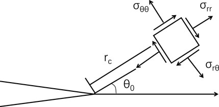
The stress intensity factor is a critical parameter that governs the singular stress field at the crack tip. It was once thought that this singularity was highly pronounced and that the stress intensity factor alone was responsible for controlling crack initiation and propagation at the crack tip, the distribution of stress field at the crack tip is shown as Figure 1. Current research shows that higher-order terms in the Williams series solution also affect crack initiation, especially when Mode II cracks are dominant. In 1957, based on the analysis of the stress field at the crack tip, Williams provided an infinite series expansion of the stress field at the crack tip, as expressed in Equation 3,
Where, the first-order coefficients A1 and B1 in the Williams series expansion correspond to the stress intensity factors KI and KII respectively, the second-order coefficient A2 corresponds to the T-stress, and the second-order term corresponding to B2 is zero, as shown in Equation 4,
In the equation, σrr, σθθ, and τrθ are stress components at the crack tip in polar coordinates, MPa.
2.2 Fracture parameter calculation method
The American company HKS has developed the ABAQUS software based on finite element theory. This software boasts powerful functionalities, capable of addressing both linear and complex nonlinear problems effectively. ABAQUS features dedicated modules for fracture mechanics analysis, employing stress singular elements to simulate the singular stress field at crack tips. It can solve numerous fracture parameters such as stress intensity factors, T-stress, and J-integral. The concept of the J-integral is rooted in the theory of energy conservation, meaning it is not fundamentally reliant on the singular stress field at the crack tip. However, calculating stresses and strains along a closed path in numerical analysis can be impractical. To overcome this challenge, Shih, Raju, and others proposed using area or volume integrals instead of line integrals for the numerical computation of the J-integral. Generally, the stress intensity factor K can be computed from the J-integral. Similarly to the calculation of fracture toughness K, the T-stress is also computed based on the interaction integral method. In 1999, the interaction integral method was defined by Moes et al. as shown in Equation 5,
In which,
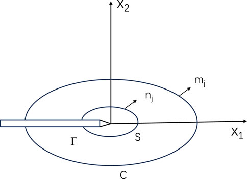
The diagram in Figure 2 illustrates the concept of interaction integral. Moes also proposed that as the integration path
To facilitate the solution of the above equation, we typically convert Equation 6 into an area integral. As shown in Figure 2, we introduce a contour C outside the original path and enclose this path. We use the symbol S to represent the area enclosed by the two paths. Thus, the expression for the interaction integral variables is modified to Equation 7,
In the equation, q represents the weight function, which takes the value of one inside
3 Establishment and validation of finite element models
A review of existing literature and methods reveals that precise analytical solutions for fracture parameters, including stress intensity factors and T-stress, for semi-circular bend specimens under three-point bending have not yet been achieved. However, finite element methods for addressing stress-related issues have gained widespread acceptance. Consequently, this study utilizes finite element analysis to determine the fracture parameters of semi-circular bend specimens.
3.1 Simulation and verification of fracture parameters
Since the stress intensity factor for a center-cracked disc has an accurate analytical solution, it serves as a benchmark for validating the fracture mechanics finite element simulation technique developed in this study. Following the principles outlined in the previous section for calculating fracture parameters, a finite element model of a center-cracked disc was established. The material properties were set to linear elasticity with an elastic modulus of 4.87 GPa and a Poisson’s ratio of 0.388. The diameter of the disc was set to 60 mm. The model elements consisted of eight-nodded quadrilateral plane strain elements (CPE8). The disc specimen model is illustrated in Figure 3.
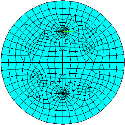
Figure 3. Numerical model of a center cracked circular disk specimen with a relative crack length of 0.5.
To simulate the stress singularity at the crack tip, a “collapse element” was placed at the crack tip. The contour integral region was set with a radius of 2 mm and divided into 20 segments. Previous research has shown that the dimensionless stress intensity factor is solely a function of specimen size and is independent of material properties such as elastic modulus and Poisson’s ratio. Therefore, these variables were not further investigated in the numerical model presented in this paper.
Figure 4 presents a comparison between the numerical and analytical solutions for the dimensionless stress intensity factor in Mode I (opening mode) across varying crack inclination angles (the angle between the crack plane and the loading direction) and different relative crack lengths. The black curve and squares illustrate the trend of the dimensionless stress intensity factor as it decreases gradually with increasing crack inclination angles. Conversely, the blue curve and circles depict how the dimensionless stress intensity factor increases progressively with greater relative crack lengths. The numerical results for the Mode I stress intensity factor, across different crack inclination angles and crack lengths, exhibit minimal discrepancies when compared to the analytical solutions, thereby confirming the accuracy of the model employed in this study.
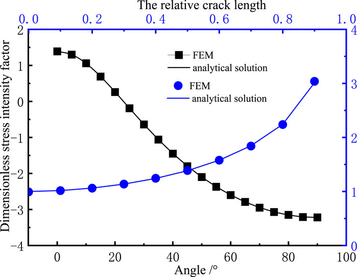
Figure 4. Non-dimensional stress intensity factor of a center-cracked circular disk specimen with a relative pre-crack length of 0.5.
3.2 Model establishment
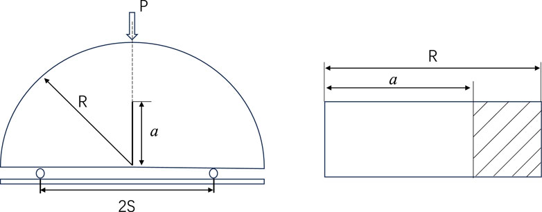
The three-point bending semi-circular disc specimen is the most commonly used type in Mode I fracture research and has broad applications in mechanical studies. However, the loading configuration of the three-point bending test and the distinct geometry of the semi-circular disc specimen generate significant T-stress at the crack tip. Despite this, current practices for fracture toughness testing with this specimen do not adequately consider the influence of T-stress on the test outcomes. To investigate the effect of T-stress on the fracture toughness test results and crack propagation in rock, it is necessary to determine the magnitude of T-stress. Previous studies have mostly overlooked T-stress. In this paper, comprehensive calibration of fracture parameters for this specimen, namely, stress intensity factor and T-stress, is conducted. The geometric schematic of the three-point bend semi-circular disc specimen is illustrated in Figure 5.
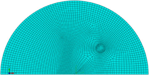
In this study, a finite element model of the three-point bending semi-circular disc specimen was developed based on the fracture parameter calculation method, as illustrated in Figure 6. The material properties were consistent with those of the center-cracked disc specimen. The radius of the semi-circular disc was R=30 mm, and the applied concentrated load was set to 1 N. With a selected support point spacing of 2 S, the range of the initial crack length to radius ratio a/R varied from 0.1 to 0.9 with a step size of 0.1. In the finite element model, the crack tip was divided into 20 segments within a radius of 2 mm, and the singularity at the crack tip was simulated using “singular elements”.
Enlarge the mesh refinement around the pre-existing crack tip, as shown in Figure 7.
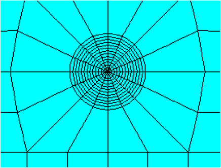
Figure 7. Mesh division at the crack tip (Wen et al., 2024).
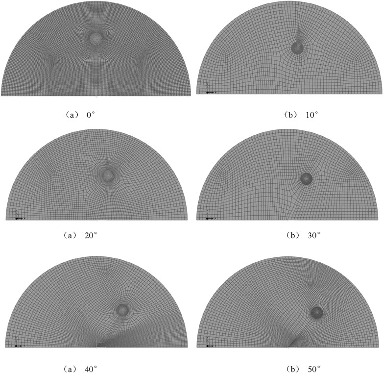
The pre-existing crack is set at angles of 0°, 10°, 20°, 30°, 40°, 43°, 47°, and 50° with respect to the loading direction. The corresponding models are established as shown in Figure 8.
In theory, the associated integral is path-independent, allowing for arbitrary selection of the integration contour. However, due to the stress singularity near the crack tip, integrating along contours that are too close to the crack tip can introduce significant errors in the results. To improve the accuracy of the finite element calculations, this study adopts integration contours away from the crack tip. The dimensionless T-stress simulation results for a semi-circular disc with a relative crack length of 0.5 are shown in Figure 9. It can be observed that the results of integration along different contours are almost identical, ensuring the path-independence of the associated integral.
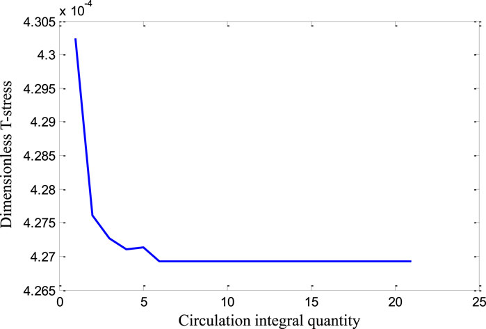
Figure 9. Graph of the dimensionless T-stress integral results for different encirclement paths (Wen et al., 2024).
4 Results and analysis of fracture parameter calculations
The formulas for calculating fracture parameters of the three-point bend semi-circular disc provided by the International Society for Rock Mechanics are given as Equations 8, 9,
The formula for calculating the T-stress of the three-point bend semi-circular disc specimen is given by Equation 10,
In which, P represents the maximum load on the displacement curve of the rock fracture test, N; KI denotes the mode I fracture toughness of the rock, MPam1/2; KII represents the mode II fracture toughness of the rock, MPam1/2; T represents the T-stress of the rock, MPa; YI, YII, and T* respectively denote the dimensionless stress intensity factors and dimensionless T-stress of the SCB specimen. R is the radius of the semi-circular disc specimen, mm. B is the thickness of the semi-circular disc specimen, mm.
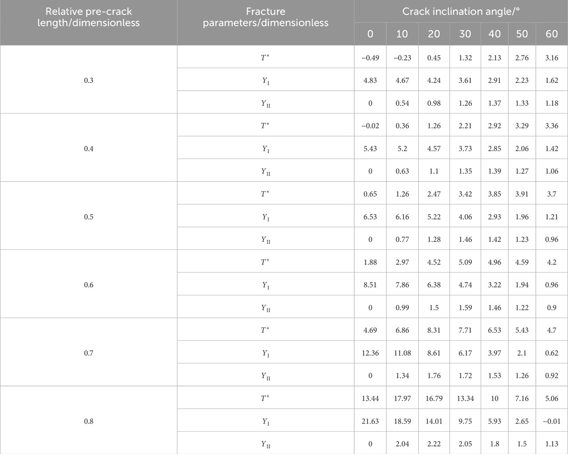
Based on the above model, stress intensity factors K and T-stress T were calculated for different crack lengths a, crack angles θ, and support point spacings S. The calculated results are listed in Table 1 and plotted in Figure 10.
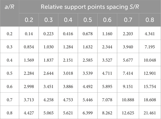
Table 1. Dimensionless stress intensity factor YI for three-point bending semi-circular disc specimen.
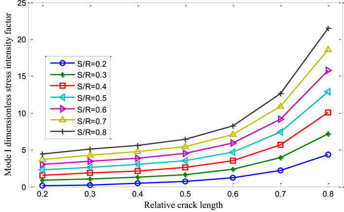
Figure 10. Variation law of the dimensionless stress intensity factor YI for the three-point bending disc specimen with an opening-type crack.
Table 1 and Figure 10 illustrate the variation of the dimensionless stress intensity factor YI for the three-point bend semi-circular disc specimen under pure mode I loading. From these, the following conclusions can be drawn,
(1) For a specific support point spacing S, YI increases with an increase in relative crack length a/R. Similarly, for a specific crack length, YI increases with an increase in support point spacing.
(2) The larger the relative crack length, the greater the increase in YI. However, if the relative crack length becomes too large, it can introduce errors in fracture toughness test results. Therefore, it is recommended to choose a relative crack length between 0.2 and 0.6.
Table 2 and Figure 11 illustrate the variation of the dimensionless T-stress for the three-point bend semi-circular disc specimen under pure mode I loading. From these, the following conclusions can be drawn, (1) When the relative crack length a/R is less than or equal to 0.5, the dimensionless T-stress is negative. (2) With the gradual increase in relative crack length, the dimensionless T-stress of the three-point bend semi-circular disc specimen initially decreases and then increases.
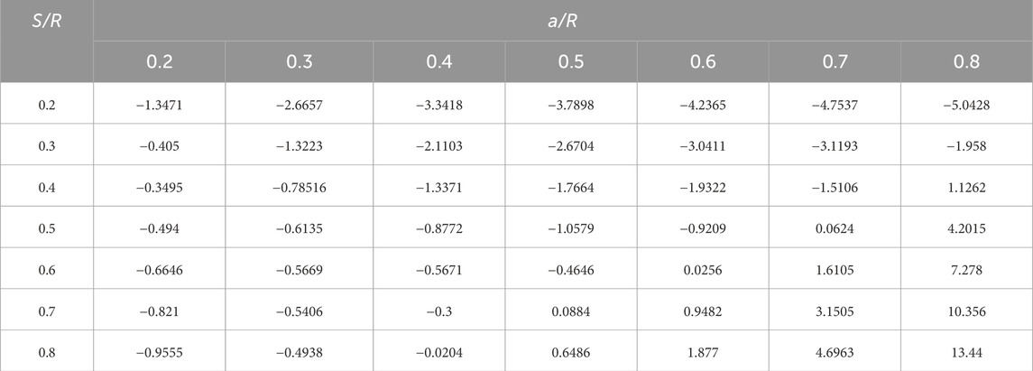
Table 2. Dimensionless T stress for the three-point bending semi-circular disc specimen with a pure mode I crack.
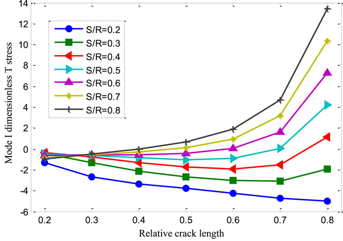
Figure 11. Variation of dimensionless T stress for the three-point bending semi-circular disc specimen with a pure mode I crack.
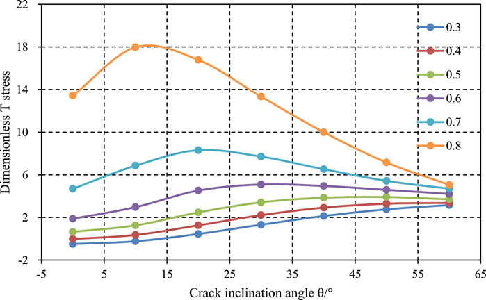
Tables 3, along with Figures 12–14, illustrate the variation trends of fracture parameters (dimensionless stress intensity factors YI and YII、, and dimensionless T-stress T* for the three-point bend specimen with a relative support point spacing of 0.8, concerning the crack angle and relative crack length. From the trend of the dimensionless T-stress, it can be observed that when the relative support point spacing S/R is 0.8, the dimensionless T-stress increases with increasing relative crack length. This suggests that T-stress has a greater impact on rock fracture as the relative crack length increases. Therefore, it is advisable to choose appropriate specimen dimensions to minimize the influence of T-stress on fracture toughness. Additionally, as the crack loading angle increases, the T-stress value also increases. This indicates that under mixed-mode fracture conditions, T-stress has a more pronounced effect on fracture behavior. This is because T-stress is a component of stress parallel to the crack plane, whereas opening mode fracture loads are perpendicular to the crack plane, making the influence of T-stress less significant in purely opening mode fractures.
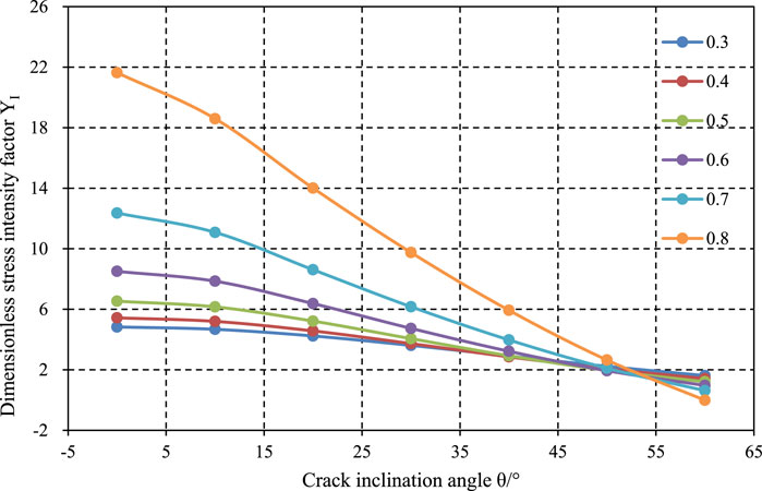
Figure 13. Variation law of dimensionless stress intensity factor YI under relative support point spacing of 0.8.
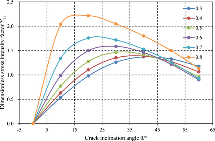
Figure 14. Variation law of dimensionless stress intensity factor YII under relative support point spacing of 0.8.
5 Conclusion
The three-point bending semi-circular specimen is widely recognized for testing rock fracture toughness. However, analytical solutions for the fracture parameters of these specimens are not available. To calibrate the fracture parameters of three-point bending semi-circular specimens, this study develops a model incorporating prefabricated cracks. Numerical calculations provide stress intensity factors and T-stress values for semi-circular specimens with varying crack lengths and spans. The study reaches the following conclusions.
(1) For a specific support distance S, the dimensionless stress intensity factor YI increases with the relative crack length. For a fixed crack length, the dimensionless stress intensity factor YI gradually increases with the support distance.
(2) As the relative crack length increases, the dimensionless stress intensity factor also increases. However, if the relative crack length becomes too large, it may lead to increased error in fracture toughness test results. Therefore, it is advisable to maintain the relative crack length within the range of 0.2–0.6.
(3) When the relative crack length a/R≤0.5, the dimensionless T-stress is negative. As the relative crack length increases, the dimensionless T-stress in three-point bending semi-circular specimens first decreases and then begins to increase.
(4) In I-II mixed-mode fractures, the influence of T-stress is more significant. This is because T-stress is a stress component parallel to the crack plane, whereas the loading in opening mode fractures is perpendicular to the crack plane, rendering the impact of T-stress almost negligible in purely opening mode fractures.
Data availability statement
The original contributions presented in the study are included in the article/supplementary material, further inquiries can be directed to the corresponding authors.
Author contributions
JW: Writing–original draft, Writing–review and editing. HW: Writing–original draft, Writing–review and editing. ZY: Writing–original draft, Writing–review and editing. QL: Writing–original draft, Writing–review and editing. CW: Conceptualization, Data curation, Formal Analysis, Funding acquisition, Investigation, Methodology, Project administration, Resources, Software, Supervision, Validation, Visualization, Writing–original draft, Writing–review and editing.
Funding
The author(s) declare financial support was received for the research, authorship, and/or publication of this article. The research is granted by China Petrochemical Key Laboratory of Geophysics Project, research on Physical Simulation Experiments of Hydraulic Fracturing in Terrestrial Shale and Exploration of Fracture Initiation and Propagation (KLP24030); and Tianshan Talent Training Program, research on Hydrocarbon Accumulation Mechanism and Efficient Exploration Techniques for Deep Marine Carboniferous Volcanic Rocks in the Tuha Exploration Area (2023TSYCCX0002).
Conflict of interest
Author JW was employed by SINOPEC Geophysical Research Institute Co., Ltd.
The remaining authors declare that the research was conducted in the absence of any commercial or financial relationships that could be construed as a potential conflict of interest.
Publisher’s note
All claims expressed in this article are solely those of the authors and do not necessarily represent those of their affiliated organizations, or those of the publisher, the editors and the reviewers. Any product that may be evaluated in this article, or claim that may be made by its manufacturer, is not guaranteed or endorsed by the publisher.
References
Aliha, M. R. M., Ayatollahi, M. R., Smith, D. J., and Pavier, M. (2010). Geometry and size effects on fracture trajectory in a limestone rock under mixed mode loading. Eng. Fract. Mech.77 (11), 2200–2212. doi:10.1016/j.engfracmech.2010.03.009
Atkinson, C., Smelser, R. E., and Sanchez, J. (1982). Combined mode fracture via the cracked Brazilian disk test. Int. J. Fract.18 (4), 279–291. doi:10.1007/bf00015688
Bazant, Z. P., and Chen, E. P. (1997). Scaling of structural failure. Appl. Mech. Rev.50 (10), 593–627. doi:10.1115/1.3101672
Bažant, Z. P., and Kazemi, M. T. (1991). Size dependence of concrete fracture energy determined by RILEM work-of-fracture method. Int. J. Fract.51 (2), 121–138. doi:10.1007/978-94-011-3638-9_9
Dong, S. M., Wang, Y., and Xia, Y. M. (2003). Stress intensity factor under concentrated load of circular crack disc. J. Univ. Sci. Technol. China33 (3), 310–317.
Erdogan, F., and Sih, G. C. (1963). Closure to iscussion of ‘on the crack extension in plates under plane loading and transverse shear’ (1963, ASME J. Basic eng., 85, pp. 525–527). J. Basic Eng.85 (4), 527. doi:10.1115/1.3656899
Fengjiao, W., He, Xu, Liu, Y., Meng, X., and Liu, L. (2023). Mechanism of low chemical agent adsorption by high pressure for hydraulic fracturing-assisted oil displacement technology: a study of molecular dynamics combined with laboratory experiments. Langmuir39 (46), 16628–16636. doi:10.1021/acs.langmuir.3c02634
Fowell, R. J. (1995). Suggested method for determining mode I fracture toughness using Cracked Chevron Notched Brazilian Disc (CCNBD) specimens. Int. J. Rock Mech. Min. Sci. and Geomechanics Abstr.32 (1), 57–64. doi:10.1016/0148-9062(94)00015-u
Huang, Y. G., Wang, L. G., Chen, J. R., et al. (2015). Theoretical analysis of determining rock tensile strength by platform Brazilian split test. Rock Soil Mech.36 (3). doi:10.16285/j.rsm.2015.s1.048
Isrm, ISRM (1978). Suggested methods for determining tensile strength of rock materials. Int. J. Rock Mech. and Min. Sci. and Geomechanics Abstr.15 (15), 99–103. doi:10.1016/0148-9062(78)90025-4
Jia, X. M., and Wang, Q. Z. (2003a). Stress intensity factor calibration of ISRM rock fracture toughness new specimen CCNBD. Chin. J. Rock Mech. Eng.22 (8), 1227–1233. doi:10.3321/j.issn:1000-6915.2003.08.005
Jia, X. M., and Wang, Q. Z. (2003b). Wide range stress intensity factor calibration of the CCNBD brittle rock fracture test specimen. Rock Soil Mech.24 (6), 907–912. doi:10.3969/j.issn.1000-7598.2003.06.009
Kuruppu, M. D., Obara, Y., Ayatollahi, M. R., et al. (2013) “ISRM-suggested method for determining the mode I static fracture toughness using semi-circular bend specimen,” in The ISRM suggested methods for rock characterization, testing and monitoring: 2007-2014. Springer International Publishing, 107–114. doi:10.1007/978-3-319-01928-9_10
Lan, M., Waisman, H., and Harari, I. (2013). A High-order extended finite element method for extraction of mixed-mode strain energy release rates in arbitrary crack settings based on Irwin's integral. Int. J. Numer. Methods Eng.96 (12), 787–812. doi:10.1002/nme.4584
Li, Z. N. (2012). Engineering fracture mechanics. Beijing University of Aeronautics and Astronautics Press.
Liang, Y. L. (2011). Study on the influence of prefabricated crack shape of circular disk specimens on the test of rock fracture toughness[D]. Henan Polytechnic University.
Lin, J., Dong, C., Lin, C., Duan, D., Ma, P., Zhao, Z., et al. (2024a). The impact of tectonic inversion on diagenesis and reservoir quality of the oligocene fluvial sandstones: the upper huagang formation, xihu depression, east China sea shelf basin. Mar. Petroleum Geol.165, 106860. doi:10.1016/j.marpetgeo.2024.106860
Lin, Q., Cao, P., Wen, G., Meng, J., Cao, R., and Zhao, Z. (2021). Crack coalescence in rock-like specimens with two dissimilar layers and pre-existing double parallel joints under uniaxial compression. Int. J. Rock Mech. Min. Sci.139, 104621. doi:10.1016/j.ijrmms.2021.104621
Lin, Q., Zhang, S., Liu, H., and Shao, Z. (2024b). Water saturation effects on the fracturing mechanism of sandstone excavating by TBM disc cutters. Arch. Civ. Mech. Eng.24, 154. doi:10.1007/s43452-024-00964-z
Maiti, S. K., and Prasad, K. S. R. K. (1980). A study on the theories of unstable crack extension for the prediction of crack trajectories. Int. J. Solids Struct.16 (6), 563–574. doi:10.1016/0020-7683(80)90006-2
Miao, X. T., Zhou, C. Y., Lv, F., and He, X. H. (2017). Three-dimensional finite element analyses of T-stress for different experimental specimens. Theor. Appl. Fract. Mech.91, 116–125. doi:10.1016/j.tafmec.2017.04.018
Mirsayar, M. M. (2015). Mixed mode fracture analysis using extended maximum tangential strain criterion. Mater. and Des.86, 941–947. doi:10.1016/j.matdes.2015.07.135
Sih, G. C. (1974). Strain energy density factor applied to mixed mode crack problems. Int. J. Fract.10 (3), 305–321. doi:10.1007/bf00035493
Sih, G. C., Paris, P. C., and Irwin, G. R. (1965). On cracks in rectilinearly anisotropic bodies. Int. J. Fract. Mech.1 (3), 189–203. doi:10.1007/bf00186854
Wang, F., Xu, H., Liu, Y., Meng, X., and Liu, L. (2023). Mechanism of low chemical agent adsorption by high pressure for hydraulic fracturing-assisted oil displacement technology: a study of molecular dynamics combined with laboratory experiments. Langmuir39 (46), 16628–16636. doi:10.1021/acs.langmuir.3c02634
Wang, Q. Z. (1998). Stress intensity factors of the ISRM suggested CCNBD specimen used for mode-I fracture toughness determination. Int. J. Rock Mech. and Min. Sci.35 (7), 977–982. doi:10.1016/s0148-9062(98)00010-2
Wang, Q. Z., and Jia, X. M. (2002). Determination of elastic modulus, tensile strength and fracture toughness of brittle rocks by platform Brazilian disc specimens - Part 1: analytical and numerical results. Chin. J. Rock Mech. Eng.21 (9), 1285–1289. doi:10.3321/j.issn:1000-6915.2002.09.003
Wei, M. D., Dai, F., Xu, N. W., Liu, Y., and Zhao, T. (2017). Fracture prediction of rocks under mode I and mode II loading using the generalized maximum tangential strain criterion. Eng. Fract. Mech.186, 21–38. doi:10.1016/j.engfracmech.2017.09.026
Wen, J., Yin, Y., and Zhang, M. (2024). Experimental study on fracture toughness of shale based on three-point bending semi-circular disk samples. Processes12 (7), 1368. doi:10.3390/pr12071368
Wu, L. Z., Wang, Q. Z., and Jia, X. M. (2004). Determination of rock fracture toughness and its scale law by Brazilian disc (CCNBD) specimen. Chin. J. Rock Mech. Eng.23 (3), 383–390. doi:10.3321/j.issn:1000-6915.2004.03.015
Wu, X., and Li, X. (1989). Analysis and modification of fracture criteria for mixed-mode crack. Eng. Fract. Mech.34 (1), 55–64. doi:10.1016/0013-7944(89)90242-7
Xie, H. P., Gao, F., Ju, Y., et al. (2012). Unconventional theory and technical ideas for shale reservoir fracturing reconstruction. J. Sichuan Univ. Eng. Sci. Ed.44 (6), 1–6. doi:10.15961/j.jsuese.2012.06.001
Xie, Y., Cao, P., Jin, J., and Wang, M. (2017). Mixed mode fracture analysis of semi-circular bend (SCB) specimen: a numerical study based on extended finite element method. Comput. Geotechnics82, 157–172. doi:10.1016/j.compgeo.2016.10.012
Xu, J. G., Dong, S. M., and Hua, W. (2015). Influence analysis of confining pressure on stress intensity factor of Brazilian disc. Rock Soil Mech.36 (7), 1959–1965. doi:10.3724/SP.J.1077.2015.01959
Xu, J. G., Hua, W., and Dong, S. M. (2014). Numerical analysis of the influence of confining pressure on stress intensity factor of Brazilian disc. J. Solid Mech. (S1), 147–152. doi:10.3724/SP.J.1077.2014.00147
Xue, Y., Li, X., Liu, J., Ranjith, P. G., Gao, F., Cai, C., et al. (2024). An experimental study on mechanical properties and fracturing characteristics of granite under high-temperature heating and liquid nitrogen cooling cyclic treatment. Geoenergy Sci. Eng.237, 212816. doi:10.1016/j.geoen.2024.212816
Yao, F. (2004). Rock fracture toughness during hydraulic fracturing extension process. Chin. J. Rock Mech. Eng.23 (14), 2346–2350. doi:10.3321/j.issn:1000-6915.2004.14.041
Zhang, J., Lin, C., Tang, H., Wen, T., Tannant, D. D., and Zhang, B. (2024a). Input-parameter optimization using a SVR based ensemble model to predict landslide displacements in a reservoir area–A comparative study. Appl. Soft Comput.150, 111107. doi:10.1016/j.asoc.2023.111107
Zhang, J., Tang, H., Li, C., Gong, W., Zhou, B., and Zhang, Y. (2024b). Deformation stage division and early warning of landslides based on the statistical characteristics of landslide kinematic features. Landslides21 (4), 717–735. doi:10.1007/s10346-023-02192-7
Zhang, M., Fan, X., Zhang, Q., Yang, B., Zhao, P., Yao, B., et al. (2021a). Influence of multi-planes of weakness on unstable zones near wellbore wall in a fractured formation. J. Nat. Gas Sci. Eng.93, 104026. doi:10.1016/j.jngse.2021.104026
Zhang, M., Fan, X., Zhang, Q., Yang, B., Zhao, P., Yao, B., et al. (2021b). Parametric sensitivity study of wellbore stability in transversely isotropic medium based on poly-axial strength criteria. J. Petroleum Sci. Eng.197, 108078. doi:10.1016/j.petrol.2020.108078
Zhang, M., Fan, X., Zhang, Q., Yang, B., Zhao, P., Yao, B., et al. (2021c). Influence of multi-planes of weakness on unstable zones near wellbore wall in a fractured formation. J. Nat. Gas Sci. Eng.93, 104026. doi:10.1016/j.jngse.2021.104026
Zhang, M., Liang, L., and Liu, X. (2017). Analysis of the influence of different rock shear failure criteria on wellbore collapse pressure. Chin. J. Rock Mech. Eng.36 (S1), 3485–3491. doi:10.13722/j.cnki.jrme.2017.s1.03485
Zhengzheng, C., Xiangqian, Y., Peiding, Z., Zhenhua, L., Feng, D., Wenqiang, W., et al. (2024). Experimental study on the fracture surface morphological characteristics and permeability characteristics of sandstones with different particle sizes. Energy Sci. and Eng.12 (7), 2798–2809. doi:10.1002/ese3.1768
Zhengzheng, C., Xiangqian, Y., Zhenhua, L., Cunhan, H., Feng, D., Wenqiang, W., et al. (2024). Fracture propagation and pore pressure evolution characteristics induced by hydraulic and pneumatic fracturing of coal. Sci. Rep.14, 9992. doi:10.1038/s41598-024-60873-2
Keywords: fracture parameters, stress intensity factors, t-stress, fracture toughness, three-point bending semi-circular specimens
Citation: Wang J, Wang H, Yao Z, Li Q and Wu C (2024) Numerical calibration for fracture parameters of three-point bending semi-circular specimens. Front. Earth Sci. 12:1461736. doi: 10.3389/feart.2024.1461736
Received: 09 July 2024; Accepted: 21 August 2024;
Published: 26 September 2024.
Edited by:
Stelios M. Potirakis, University of West Attica, GreeceReviewed by:
Qibin Lin, University of South China, ChinaZhengzheng Cao, Henan Polytechnic University, China
Copyright © 2024 Wang, Wang, Yao, Li and Wu. This is an open-access article distributed under the terms of the Creative Commons Attribution License (CC BY). The use, distribution or reproduction in other forums is permitted, provided the original author(s) and the copyright owner(s) are credited and that the original publication in this journal is cited, in accordance with accepted academic practice. No use, distribution or reproduction is permitted which does not comply with these terms.
*Correspondence: Zongquan Yao, eXpxQHhqdS5lZHUuY24=; Qi Li, bGlxaUBjdWdiLmVkdS5jbg==
 Jun Wang
 Haoyi Wang2,3
 Chaodong Wu