 S. Calvari1*†
 G. Giudice1†
 R. Maugeri1†
 D. Messina1,2†
 D. Morgavi3†
 L. Miraglia1†
 A. La Spina1†
 L. Spampinato1†
- 1Istituto Nazionale di Geofisica e Vulcanologia, Osservatorio Etneo - Sezione di Catania, Catania, Italy
- 2Dipartimento di Scienze della Terra e del Mare (DiSTeM), Università di Palermo, Palermo, Italy
- 3Department of Earth Sciences (DiSTAR), University Federico II, Complesso Universitario di Monte Sant’Angelo (Ed. 10), Napoli, Italy
Lava tubes are powerful heat insulators, allowing lava to practically keep the initial temperature and travel longer distances than when freely flowing on the ground surface. It is thus extremely important to recognize how, when and where these structures form within a lava flow field for hazard assessment purposes, in order to plan possible interventions should a lava flow approach inhabited areas. Often being formed within thick and complex lava flow fields, lava tubes are difficult to detect, study and explore. In this study, we analyse the 1792–93 Etna lava flow field emplaced on a steep slope (>4°) which comprises several lava tubes located at different distances from the eruptive fissure, at different levels within the lava flow field, and showing various inner morphologies, with peculiar inner features related to their maturity and eruptive history. Our aim is to verify whether it is possible to connect the underground features with features observed on the lava flow surface in order to reconstruct the extension of the tube network and unravel the genetic processes. Our results show that, in the studied lava flow field, a clear correspondence is possible between shallow tubes emplaced late during the lava flow field growth and surface textures. In addition, vertical and horizontal tube capture is very widespread, and might be the primary process for lava tube persistence and long life. Our results might be applicable to other lava tubes on Earth and other rocky planets.
Highlights
• Long–lasting effusive eruptions on steep slopes often form extensive lava flow fields containing lava tubes.
• The insulating effect of lava tubes enables lava flow fields to reach greater lengths.
• Lava tubes may form complex networks of stacked lava tube systems merging laterally and vertically.
• Vertical tube capture undetected during an effusive eruption might cause unexpected hazard by reactivation of distal stalled lava flow fronts.
• Lava tube networks could provide shelters in the exploration of rocky planets.
1 Introduction
Two important external factors are important in governing the shape and size of long–lasting lava flow fields: i) the pattern of the discharge rate curve throughout the eruption (Wadge, 1978; Harris et al., 2007; Wadge, 1981), and ii) the ground slope, which determines the shear strain applied to the lava and ultimately the lava flow morphology and structure (Walker, 1967; Walker, 1971). Most long–lasting eruptions are characterized by a curve of discharge rate that reaches its climax during the first few days and then exponentially declines (Wadge, 1978; Harris et al., 2011). During the initial phases of high discharge rate, one or more arterial lava flows develop, showing mainly a‘ā surface morphology and sheet flows structure. Initially spreading in all directions, sheet flows gradually develop master channels (Lipman and Banks, 1987; Kilburn and Guest, 1993; Guest et al., 2012; Calvari, 2019). If the lava supply is steady enough over time, lava flows mature and master channels may gradually seal to form master tubes (Greeley, 1987; Calvari and Pinkerton, 1998; Calvari and Pinkerton, 1999). When effusion rate declines, these master tubes drain, and if their roofs and inner walls are not completely solidified, they may collapse. Conversely, during temporary surges, or more generally when the inflow into a lava pool is greater than the flow out of the pool, they may inflate to form tumuli (lava moulds caused by the magmastatic pressure of fluid lava beneath the chilled and solid crust; Walker, 1991; Kauahikaua et al., 1998; Thordarson, 2000; Duncan et al., 2004) that feed the opening of secondary ephemeral vents and marginal breakouts (Mattox et al., 1993; Calvari and Pinkerton, 1998), mainly of pahoehoe morphology (Walker, 1991; Kilburn and Guest, 1993). During the declining discharge rate phase, surface breakouts of lava from weak points of the tube occur progressively closer to the vent, consistent with declining efficiency in lava transport (Mattox et al., 1993; Kauahikaua et al., 1996). This results in a much thicker lava flow field close to the main vent than in the distal portions (e.g., Mattox et al., 1993; Fornaciai et al., 2021). The local and temporary overpressure of lava accumulating below a coherent crust causes the formation of tumuli and inflation clefts (Walker, 1991; Hon et al., 1994; Duncan et al., 2004) that are common in the proximal to middle zones of a lava flow field emplaced on steep slopes (more than 4°; Lyell, 1858; Thordarson and Sigmarsson, 2009), given that a decreased effusion rate does not allow these structures to form beyond the margins of the already emplaced lava flow field (Guest et al., 2012). However, it is important to point out that this statement holds for lava flow fields emplaced on steep slopes, and is not pertinent to pahoehoe lava flow fields emplaced on a low slope (less than 4°), such as Laki and Holuhraun in Iceland, where long-lasting effusive events produced lava flow fields extending well beyond the initial high-discharge lava phase, and developed inflation features, such as tumuli, in the distal parts of their flow fields (e.g., Thordarson and Self, 1993; Rossi, 1996; Thordarson, 2000; Thordarson et al., 2003; Thordarson and Sigmarsson, 2009; Pedersen et al., 2017).
The normal progression of a long-lasting, mainly lava flow field emplaced on a steep slope typical of Etna volcano (Kilburn and Lopes, 1988; Kilburn and Lopes, 1991), and of a predominantly pahoehoe lava flow field typical of Kīlauea volcano (Mattox et al., 1993; Kauahikaua et al., 1998), is an initial increase in length, followed by an increase in width, and then by an increase in thickness (Kilburn and Lopes, 1988; Kilburn and Lopes, 1991; Mattox et al., 1993). The overlapping of several lava flows, possibly containing tubes, will generate complex, overlapped and interconnected lava tube systems (Mattox et al., 1993; Calvari et al., 1994; Calvari and Pinkerton, 1998; 1999; Kauahikaua et al., 1998).
Etna volcano in Sicily, southern Italy (Figures 1A, B) is famous for being a typically effusive volcano, with extensive lava flow fields shaping its slopes. The 1792–93 Etna eruption (Figure 1C) is one of the best examples of emplacement of a complex lava flow field emplaced on a steep slope having both a‘ā and pahoehoe surface morphologies.
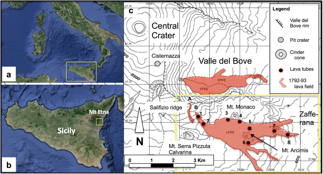
Figure 1. (A) Google Map of Italy, with Sicily inside the yellow rectangle, magnified in (B). (B) Sicily, with the yellow square showing Mt Etna’s position, displayed in (C). (C) The SE flank of Etna volcano with the 1792–93 lava flow fields (in red), modified after Gottini et al. (1980), with the yellow rectangle displaying the area of Figure 3. The black dots mark the entrances of the main lava tubes: 1) Tre Livelli; 2) KTM; 3) Cassone; 4) Coniglio; 5) Acqua Vitale; 6) Mt. Arcimis; 7) Morto; 8) La Fenice. A is the first effusive vent opened along the Salifizio ridge; B is the main effusive vent feeding the lava flow field spreading on the south flank of the volcano. The elevation is in meters above sea level (m a.s.l.). The coordinates of the topographic map are WGS 84.
The 1792–93 lava flow field studied in this paper is one of the two that formed during the eruption. The first field developed within the Valle del Bove depression (Figure 1C) and is now covered by more recent lava flows. The second and still exposed 1792–93 lava flow field extends on a steep slope on the south flank of the volcano between ∼1900 m and 700 m above sea level (a.s.l.), for a total length of ∼6.5 km, reaching the outskirts of Zafferana (Figure 1C). As this lava flow field is crossed along most of its length by the SP 92 road, it has been possible to discover and survey a number of lava tubes (Bella et al., 1982; Balsamo et al., 1994; Calvari and Liuzzo, 1999). This is also one of the few lava flow fields on Etna which offers good exposures of several cavities formed at different distances from the main vent and in different environments, i.e., inside the eruptive fissure, along master a‘ā lava channels, on lateral and distal branches, and on the final pahoehoe lobes and a‘ā channels of the lava flow field. Each of these tubes has distinctive morphologies and structures, which for the shallowest can be related to the surface features observed on the lava flow field.
To unravel the genetic relationships between the features of different tubes, in this paper we present surface and underground observations carried out on eight lava tubes that were discovered and mapped by the CSE (Centro Speleologico Etneo) and CAI (Club Alpino Italiano) speleologists within the 1792–93 lava flow field. We show examples of how the underground features of lava tubes can prove highly useful in understanding the mechanisms of emplacement of their host lava flows, their rheological state and potential hazard. Although these features are typical of the described lava flow field, many of them have also been observed in other compound lava flow fields of Etna (Guest et al., 1984; Guest et al., 2012; Calvari and Pinkerton, 1998; Calvari and Pinkerton, 1999; Duncan et al., 2004), Lanzarote in the Canary Islands (Tomasi et al., 2022), Undara in Australia (Atkinson and Atkinson, 1995; Stephenson et al., 1998), Jeju Island in South Korea (Woo et al., 2019), Saudi Arabia (Németh and Moufti, 2023), Iceland (Jonsson and Hroarsson, 1991; Hroarsson and Jonsson, 1991), and Hawai’i (Peterson and Swanson, 1974; Greeley, 1987; Hon et al., 1994; Peterson et al., 1994; Kauahikaua et al., 1998; Kempe et al., 2006; Orr, 2011), and as such they may represent key examples to interpret other long–lasting basaltic effusive eruptions forming complex lava flow fields with tube networks on Earth and other planets. In fact, due to their insulating effect that could protect people against extreme temperatures and cosmic rays, lava tubes could be used as shelters in the exploration of rocky satellites and planets, such as the Moon or Mars (Blair et al., 2017; Martin and Benaroya, 2023; Carrer et al., 2024).
2 The 1792–93 Etna flank eruption
The summit of Mt. Etna volcano had been inactive for 5 years, when in early May 1792 a column of ejecta was erupted, followed by two lava flows (Gemmellaro, 1858). One was directed westwards and stopped soon, whereas the other expanded eastward into the southern Valle del Bove depression, quickly reaching ∼5 km from the source vent (Figure 1C). This lava flow field is now buried by more recent eruptions (Gottini et al., 1980; Calvari et al., 1994) and is inaccessible. On 25 May 1792 a collapse on the western rim of the Valle del Bove formed a pit-crater named Cisternazza (Figure 1C). On 1 June, the eruptive fissure expanded further SE and crossed the southern rim of the Valle del Bove. A new high discharge effusive vent opened at the Salifizio ridge (A, Figure 1C), producing a small lava flow. The eruptive fissure propagated further eastward along the Salifizio ridge (B, Figure 1C) cutting off the lava supply to the first vent (A, Figure 1C), and forming a flow field with several lava flows spread on the south flank of the volcano, with lava branches surrounding Mt. Arcimis (Figure 1C), and reaching the village of Zafferana (Recupero, 1815). Five master channels expanded in the middle portion of the lava flow field on the south flank of the volcano (Recupero, 1815). The first vent of the second phase of this eruption (A, Figure 1C) stopped soon, whereas the second vent (B, Figure 1C) produced many flows that overlapped each other forming a stacked lava flow field. The eruption ended on 28 May 1793, after almost a year of continuous activity.
The maximum length of the lava flow fields was ∼5 km within the Valle del Bove and ∼6.5 km on the southern flank (Figure 1C), with an average thickness of 10 m (Gottini et al., 1980). The flow field covered a total surface area of 8 km2 and produced a volume of 120 × 106 m3 of lava and ∼100 × 103 m3 of pyroclasts (Gottini et al., 1980). It has an explosive index of 0.0008 (volume of pyroclasts divided by the volume of lava) and a mean eruption rate (MER; Harris et al., 2007) of 3.8 m3 s-1. This 13–month–long eruption was characterized by a continuous and very fluid lava flow output (Abb. Ferrara, cited by Recupero, 1815) spreading along the south slope of the volcano during the start of the second phase at high speed (probably several meters per second). Recupero (1815) described lava flow fronts feeding secondary flows overlapping each other and forming a complex lava flow field up to 300 feet thick (from historical report, ∼91.4 m). Its surface morphology was featured by large hummocks (tumuli), and by portions of the lava channels gradually roofing over (Recupero, 1815). By the start of 1793 the lava flow field was still active, but most of the flowing lava was confined to a system of lava tubes. It was only in May 1793 that the discharge rate declined and the eruption ceased (Recupero, 1815).
At least fifteen lava tubes have been recognised within the 1792–93 lava flow field, although not all of them were attributed to the 1792–93 lava flow field. We surveyed eight of the main tubes of the 1792–93 lava flow field, shown in Figure 1C, with their features listed in Table 1. Two of these were previously related to a lava flow field emplaced in 1634–38, namely, the Coniglio and Acqua Vitale tubes (Brunelli and Scammacca, 1975). Following Tanguy (1981), the 1634–38 lavas are of the “cicirara” type, a local name meaning chickpeas, and as such characterized by centimetre-sized macrocrysts of plagioclase, visible to the naked eye, typical of Etna’s products erupted until 1669 (Lanzafame et al., 2013). Conversely, the 1792–93 lavas contain mm-sized crystals of plagioclase, pyroxene and olivine (Corsaro et al., 2005). The samples that we collected from the Coniglio and Acqua Vitale lava tubes have the same textural features as the 1792–93 lava flow field, thus we attribute these two lava tubes to the 1792–93 eruption.
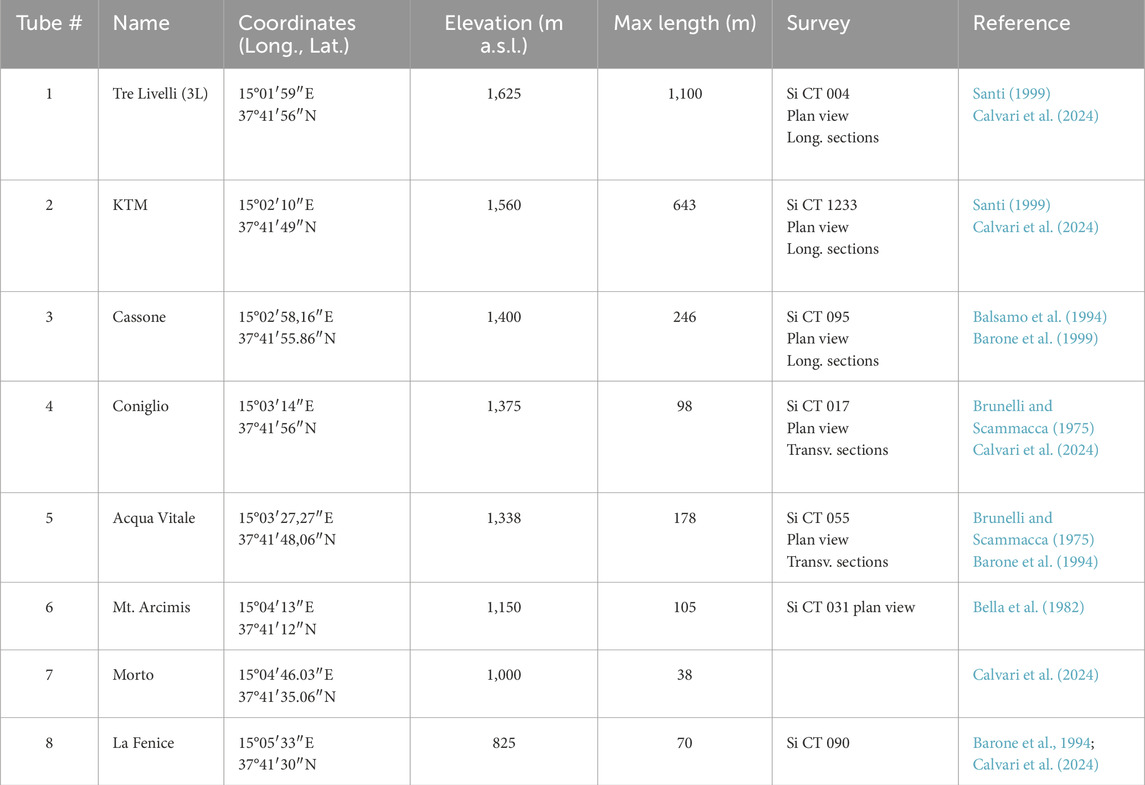
Table 1. List of the main lava tubes recognised within the 1792–93 lava flow field and of their main features. The tube number (#) refers to Figure 1C. The coordinates and elevation refer to the tube entrance.
3 Materials and methods
In this paper, we used field and aerial photographs taken by drones, helicopter photos, Google Map images and field surveys to describe the main features of the 1792–93 lava flow field and its lava tubes. We used published and new unpublished maps of the lava tubes in order to relate the surface features of the lava flow field to the morphology of the tubes inside. This enabled us to recognise the preferential paths of lava tube formation, and to correlate their inner features to the distance from the main vent and thus to the rheology of the lava flowing inside and to the morphology of the lava flow field surface. The original tube surveys carried out in the nineties by the Centro Speleologico Etneo (CSE) were repeated for this study, with care taken in connecting their position to the surface as precisely as possible. One of the described lava tubes (Morto lava tube, Figure 1C) was not previously mapped and its survey is presented here for the first time, whereas for the uppermost part of the Tre Livelli (3L) and the whole Cassone tube that are no longer accessible because of collapses, we present the old maps.
The main problem when surveying lava tubes is that magnetic anomalies can affect the horizontal angle measurements if taken using a compass, in some cases with considerable errors. This is why in the past the surveys were carried out using only angular measurements. The old maps of the lava tubes done in the nineties were carried out using a manual survey using three items: an instrument (squadro agrimensorio) that is a kind of theodolite without its optical part, useful to measure horizontal angles between polygonal survey vertices, with a theoretical resolution of 4,000 points per round angle, and a precision of about 0.1 sexagesimal degree; a clinometer, to measure the vertical angles from the horizontal plane, with resolution of about 1.0 sexagesimal degree; and a metric tape to measure distances.
The new surveys were carried out using a DistoX2 laser system, which is a modified laser rangefinder (https://paperless.bheeb.ch/; accessed on 13 May 2024 at 15.56). The DistoX2 consists of a Leica Disto X310 and an upgrade kit which adds a 3-axes compass and clinometer and a Bluetooth connection able to measure, store and send distance, vertical and horizontal angles (from magnetic north) of the survey to a smartphone app (topodroid; https://www.marcocorvi.altervista.org/caving/speleoapps/speleoapks/topodroid_apk/TopoDroidX-6.2.44-34.apk/; accessed on 13 May 2024 at 16.00). It has a resolution of 0.01 m on the distance measurement, and of 0.1 sexagesimal degrees on the angles. For the new survey using the DistoX2, which is based on an electronic magnetic compass, particular care was made to use it as far as possible from magnetic anomaly sources, such as compact lava blocks or tube walls. From our experience, it is sufficient to place the instrument 30 cm or more from the tube walls in order to obtain reliable measurements, and to alternate measurement stations at the right and left walls or on the ceiling and floor, where possible, thus compensating on average the error due to the magnetic anomalies. Another technique to minimise errors is to also measure the sides of the polygonal backwards. The uppermost portion of the 3L tube is no longer accessible because of collapses. Thus, in order to obtain a reliable map of this tube, the old field data were integrated in the new survey.
To investigate the surface features of the lava flow field and conduct detailed visual observations, we generated the orthophoto of the upper and intermediate part of the lava flow field, where the 3L and KTM tubes are located, using photogrammetric image processing techniques, known as Structure from Motion (SfM), through the use of an unmanned aerial vehicle (UAV) equipped with a digital camera (Westoby et al., 2012; Mancini et al., 2013; Pijl et al., 2019). The ground surface photos were taken with a DJI Mavic 2 Pro quadcopter with a weight of 907 g and a maximum battery life of 31 min. The quadcopter is equipped with a Hasselblad L1D-20c RGB camera with 1″CMOS and 20 MP. Considering the elevation change of the area to be surveyed (from 2000 to 1600 m a.s.l.), four flight plans were carried out at different heights using Pix4Dcapture software (version 4.13.1 for iOS). This procedure and the variations in elevation change generated a variable Ground Sample Distance (GSD). The flight altitude was set at 100 m AGL (Above Ground Level), the frontal overlap at 90%, the lateral overlap at 85% and the acquisition angle at 90° for all photogrammetric flights. These parameters produced a theoretical GSD value of 2.34 cm/pixel with a total of 736 photos acquired.
The UAV used in this study does not have precise navigation instruments. However, since centimetre accuracy on absolute coordinate positioning was not necessary for our purposes, we did not use ground control points (GCPs) for GNSS surveying. We have instead used 3 markers, whose distances were measured with the DistoX2 laser system. These measurements were used to scale the point cloud. Photogrammetric processing was performed entirely within the Agisoft Metashape® v.2. n (Agisoft LLC, St. Petersburg, Russia) through the following steps: (i) importing the dataset; (ii) camera calibration; (iii) image alignment for internal and external orientation and creation of the sparse point cloud; (iv) identification of markers and addition of scale bars; (v) alignment adjustment; (vi) creation of the dense point cloud; (vii) creation of the orthophoto. The lava flow surface below 1600 m a.s.l. and up to the lower end of the flow field (700 m a.s.l.) was investigated using Google Earth and field photos.
4 Lava flow field morphology
The three different phases of the eruption (Gottini et al., 1980) are mirrored by the morphology of the lava flow field, if we exclude the flow field that is no longer accessible. The first effusive vent on the south flank of the volcano opened on the Serra del Salifizio ridge at 2000 m a.s.l. (A; Figure 1C, 2A). From here, a thin and apparently very fluid lava flow poured out (Gottini et al., 1980), and presumably was active for just a few hours. The fluidity of the lava appears evident by the drainage of the flow surface, now located ∼1.5 m below the lateral levees on the uppermost half of the lava flow, and by the thin lateral levees, just 20–30 cm wide. The lava flow expanded south and reached a maximum distance of 1.4 km from the vent, with a lava channel between 15 and 80 m wide and lateral levees up to 1.5 m high (Figure 2A). The surface of the flow has a‘ā morphology and remained isolated on the west margin of the lava flow field (Figure 1C, 2A). No lava tubes formed along this flow. The propagation of the eruptive fissure further down slope and SE resulted in a second line of vents (B; Figure 1C, 2B). The welded spatter, a few meters thick, surrounding the eruptive fissure for several meters length (Figure 2B), testifies to the occurrence of an initial and moderate lava fountain explosive activity, followed by effusive activity from the lower end of the fissure (Vent B). Vent B and its eruptive fissure were responsible for the emplacement of the main part of the 1792–93 lava flow field cropping out on the south flank of the volcano.
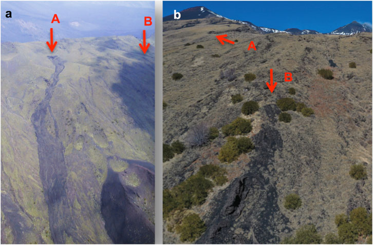
Figure 2. (A) Helicopter photo (S. Calvari) of the first vent (A, red arrow in the foreground) opened on the Serra del Salifizio ridge. The position of the B vent in the background is indicated by B and the red arrow. (B) Drone photo (D. Messina) of the eruptive fissure in the foreground (B, red arrow) opened on Serra del Salifizio ridge. The position of Vent A in the background is indicated by the red arrow.
Following Guest et al. (2012), the lava flow field can be divided into a proximal, middle and distal portion. The proximal and distal portions are mainly characterized by a‘ā surface morphology, whereas the medial portion displays mainly pahoehoe surfaces, featuring tumuli and other inflation-linked surface textures, along with several a‘ā lobe fronts feeding widespread secondary pahoehoe and toothpaste lobes from the inflation clefts. The proximal lava flow field extends from the top of the eruptive fissure at ∼ 1900 m a.s.l. to ∼1500 m a.s.l., below the SP 92 road (Figure 3). It has a length of 1.2 km, an average slope of ∼20° and is mainly a‘ā, with minor pahoehoe lobes in between. Half way along the proximal zone is a skylight that allows access to the upper tube system. This skylight opened at the front of an inflated a‘ā flow lobe, and displays typical features of a tube vertical capture, with the inflated flow front collapsed within the tube underneath (Calvari and Pinkerton, 1998). Another access is from the skylight at the side the SP 92 road (Figure 3). The medial portion of the lava flow field extends from 1500 to 1200 m a.s.l. and between 1.2 and 3.4 km distance from the main vent, has an average slope of ∼8° characterized by many tumuli of various size and shape feeding several small flows with ropy pahoehoe and toothpaste surfaces. These are interpreted as produced by the late-stage emptying of the lava tubes or by marginal breakouts (Mattox et al., 1993; Calvari and Pinkerton, 1998; Calvari and Pinkerton, 1999).
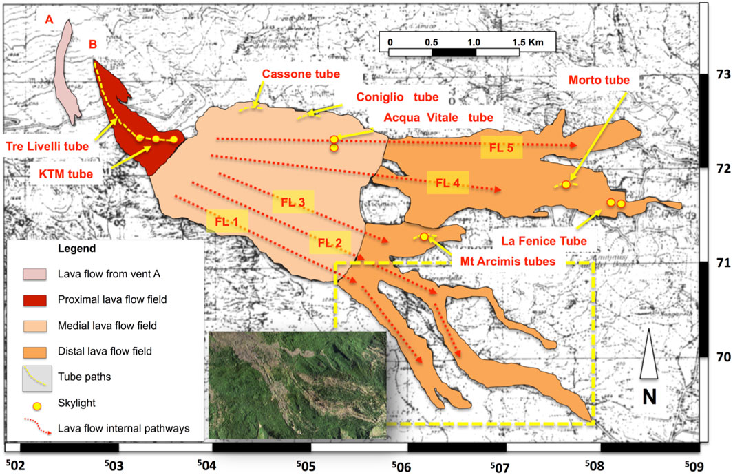
Figure 3. Map of the 1792–93 lava flow field with distinction of the proximal, medial and distal lava flow field, displaying the approximate position of the main lava tubes and skylights. A is the first vent opened on 1 June 1792 along the Salifizio ridge, B is the top of the eruptive fissure. The labels FL (lava flow) 1 to FL 5 indicate the possible path and sequence of the master channels emplaced during the eruption as described by Recupero (1815). The 2018 Google Earth map at the bottom of the figure shows the lava channels at the distal ends of FL 1 and FL 2, whose area is framed by the yellow rectangle. The coordinates of the topographic map are UTM ED50.
The distal portion of the flow field extends south of Mt Arcimis from 1200 to 700 m a.s.l. for a length of 2.7 km and with an average slope of ∼10°. It also features three lava flow branches extending in a SSE direction (FL 1, FL 2 and FL 3; Figure 3). The distal end of the lava flow field is made of a‘ā displaying well–defined lava channels especially to SSE (FL 1 and FL 2; Figure 3). These were probably emplaced during the earlier stages of the eruption when the discharge rate was high. The five red dotted arrows of Figure 3 represent the probable path of the five arterial lava flows emplaced during the early stages of the lava flow field at high rate (Recupero, 1815), and responsible for the most advanced lava flow fronts to the E and SE. It is interesting to point out that the two southernmost flows (FL 1 and FL 2; Figure 3), display at the very end well-defined lava channels and no lava tubes, whereas the number of lava tubes increases in the northern sector of the lava flow field and from FL 3 to FL 5 (Figure 3).
5 Lava tube systems
A number of lava tubes within the 1792–93 lava flow field have been explored and surveyed (Brunelli and Scammacca, 1975; Bella et al., 1982; Balsamo et al., 1994). It is here worth noting that exploration of lava tubes on Etna does not require any permission as at the time of writing this manuscript they are not yet considered geoheritage features. There are at least fifteen lava tubes known in this flow field, but many are small and short (a few meters wide and long). We consider here only the main eight tubes. Listed by increasing distance from the eruptive fissure, these are: Tre Livelli (3L), KTM, Cassone, Coniglio, Acqua Vitale, Mt. Arcimis, Morto and La Fenice (Table 1; Figure 1C, 2, 3). In the following sections, we describe the features observed inside them, seeking to find a connection with the surface morphology and with the emplacement history of the host flow, where feasible.
The proximal lava flow field contains a system of stacked tube networks forming at least three overlapping cavities, comprising the 3L and KTM tube systems (Figure 1C, 3). In the medial portion of the lava flow field, where inflation structures are ubiquitous, are the Cassone, Coniglio and Acqua Vitale tubes (Figure 1C, 3; Table 1). Subordinate pahoehoe surfaces with narrow and braided lava channels and slightly inflated structures characterize the distal flow field area to the south and east of Mt. Arcimis, where the tubes of Mt. Arcimis (FL 3) are located (Figure 3). Flow 3 is the shortest (FL 3; Figure 3), stopping before reaching the base of Mt Arcimis, comprising several small, channel-fed pahoehoe lobes forming at least 2 lava tubes aligned along the same direction, with only the lowest one mapped and split in three branches. It is worth noting here that pahoehoe lava at Etna is different from the Hawaiian counterpart, and has a rough surface which is however much smoother and is distinguishable from the a‘ā texture (Kilburn, 1990; Kilburn, 1993; Kilburn and Guest, 1993). This can be categorized as a pahoehoe type transitional to a‘ā, such as the spiny, slabby, toothpaste, and shark–skin pahoehoe described by Self et al. (1998) and Harris et al. (2017). Thus, when in the following we mention a pahoehoe texture, it is to this transitional type that we refer.
Flow 4 (FL 4; Figure 3) expanded ESE and displays the most distal portion from the vent forming several pahoehoe lava channels with ubiquitous inflation features. Along its main direction of emplacement there are the Morto and La Fenice tubes, the latter of which is located at the lowest eastern end of the lava flow field (Figure 3). Flow 5 (FL 5; Figure 3) is the northernmost branch of the lava flow field, and has five major tubes along its path: the 3L, KTM, Cassone, Coniglio, and Acqua Vitale tubes. The lowest end of Flow 5 (Figure 3) is marked by a‘ā flows with no evidence of lava channels.
5.1 The Tre Livelli - KTM tubes system
The 3L and KTM (3L-KTM) tubes comprise the same tube system interrupted by an undrained passage in between. They developed partly within the eruptive fissure (3L) and partly in the proximal and upper northern part of the lava flow field (KTM) along the FL 5 pathway (Figure 3). The 3L-KTM tube extends between the main vent (B; Figure 1C, 2) and up to ∼1.4 km distance down slope, where the present day surface has an average slope of ∼20° along the eruptive fissure (3L) and ∼10° further down (KTM). The 3L-KTM tube system is at the highest elevation of all of the 1792–93 tubes, ranging from 1850 to 1450 m a.s.l. (Corsaro et al., 1995). It starts just 50 m below the top surface of the eruptive fissure and extends through the proximal portion of the lava flow field in a NW-SE direction (Figures 4A–C). One of the two entrances is located along the SP 92 road (Figure 3A, 4A–C, E), and a secondary entrance a few tens of meters upslope along the eruptive fissure through a skylight (Figures 4A–C, F). The planimetric map (Figure 4A) was done by the CSE during the old survey (Santi, 1999), whereas the longitudinal section (Figure 4B) is from our new survey.
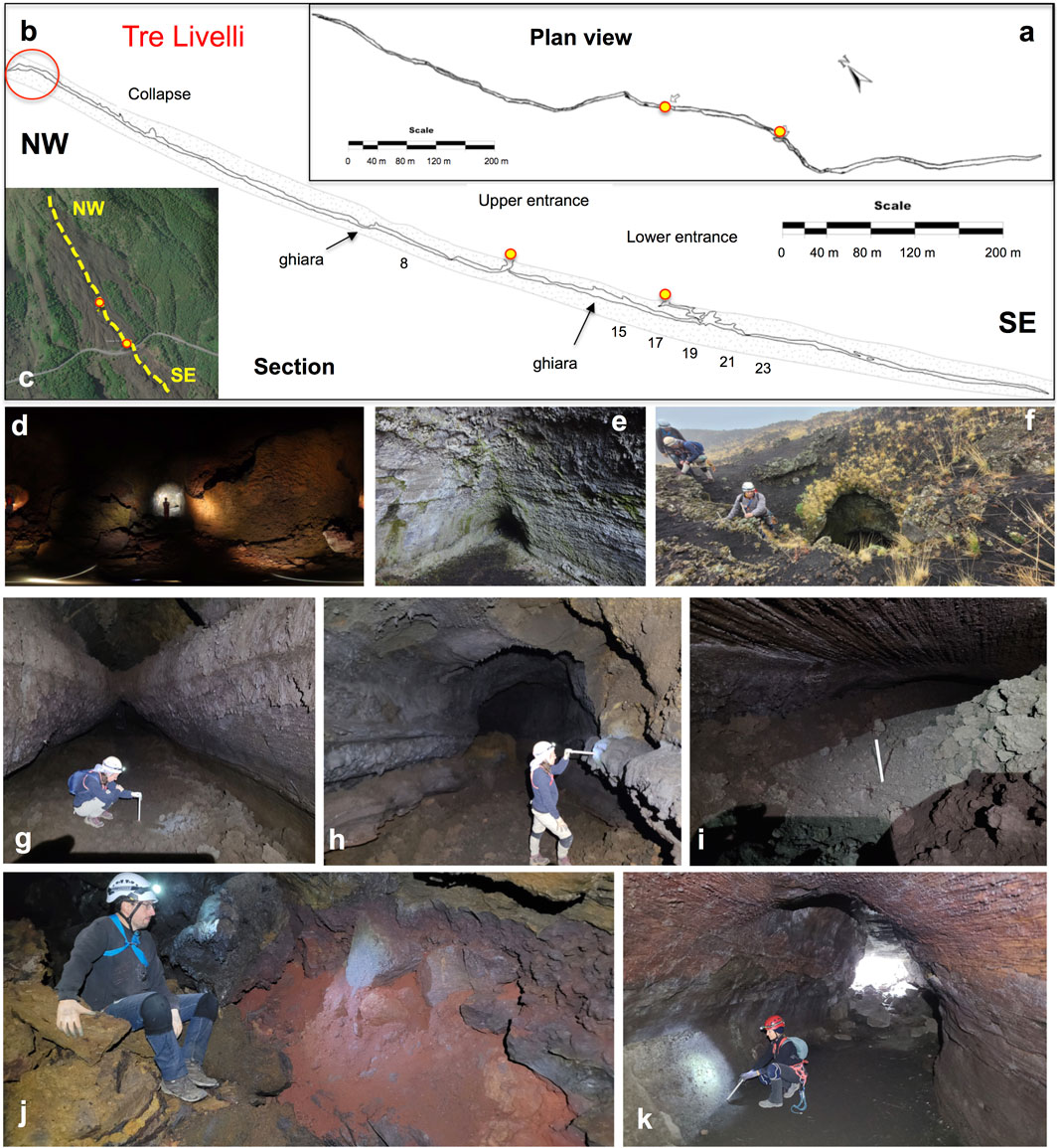
Figure 4. (A) Plan view (survey by Centro Speleologico Etneo), and (B) longitudinal section of the Tre Livelli tube. The red circle displays the horizontal portion of the longitudinal section located within the upper part of the eruptive fissure. (C) Google Earth map of the 1792–93 eruptive fissure and upper lava flow field with the path of the Tre Livelli tube marked by the yellow dotted line. The two yellow circles in (A–C) mark the skylight entrances. (D) Photo of the uppermost portion of the tube looking up at the horizontal surface within the eruptive fissure (red circle in (B)). Note the reddish inner walls. (E) Photo of the tube at the lower entrance along the road, showing a wide chamber with a small vent at the bottom. (F) Photo of the upper entrance of the cave, showing at least three overlapped lava flow units. (G) Photo taken between the points 15 and 19 (see (B)) looking down slope, showing two overlapped tubes joined by vertical capture. (H) Photo taken between the points 17 and 21 (see (B)) looking down slope, showing several lateral benches produced by flow stagnation. (I) Photo taken between the points 19 and 23 (see (B)) looking down slope, showing a narrow chamber and the roof with striations parallel to flow direction. (J) Photo taken close to point 8 (see (B)) showing the “ghiara”, local name for the ground baked by the lava flow erupted during the earlier phases of the eruption. (K) Photo of the lower tube entrance showing horizontal striations on the walls and roof, with the upper half of the cavity showing a reddish colour. The floor of all sections is made of a‘ā rubble. Photos (D, F–K) are by G. Giudice; photo (E) is by R. Maugeri.
The tube extends both upslope of the SP 92 road for about 700 m, reaching almost the top end of the eruptive fissure, and downslope for about 400 m, where it extends along the master pathway feeding most of the eruption. This is the longest lava tube on Etna (Table 1). The name Tre Livelli (Three Layers; 3L) indicates that it is composed by three vertically stacked tubes partially coalescing vertically (Figure 4B, points 17–19 of the transversal section close to the lower entrance), that merge together close to the lower entrance by vertical capture (Calvari and Pinkerton, 1999) through a 6-m-deep pit characterized by vertical grooves along its wall. The stacking of three parallel tubes occurs along 60 m length of the tube and close to the SP 92 road (Figures 4B, C). The upper part of the cavity lies within the eruptive fissure, and starts with a narrow and ∼30 m long horizontal path (Figures 4B, D) typical on Etna of cavities emplaced within eruptive fissures, where the horizontal floor is determined by a ropy pahoehoe surface left by the last lava exiting from the fissure. The short horizontal path soon becomes very steep (Figure 4B) and locally up to ∼35°, thus much steeper than the surface ground (20°), and here the tube has a straight and narrow path following the eruptive fissure (Figures 4A–C). It becomes winding down slope where the ground slope decreases (∼10°). One of the main features of this tube is the reddish coating surface, particularly evident within the eruptive fissure (Figure 4D) and close to the lower entrance (Figure 4K), whereas further down slope within the KTM this reddish surface characterizes only the lower half wall of the tube. The cavity close to the lower entrance next to the road (Figure 4E) has a wide chamber ending a few tens of meters to the north with a small ephemeral vent. By observing the inner features and the surface morphology, the cavity in the uppermost level clearly formed within a small and inflated pahoehoe breakout starting from an inflated a‘ā flow front located a few meters up slope. The vertical capture is evident in many points, and in the upper skylight it is possible to distinguish three overlapped lava flow units on top of the uppermost tube (Figure 4F). Close to the lower skylight (Figure 4G), the tube section has a typical key–hole shape evidencing vertical capture (Calvari and Pinkerton, 1999). Several lateral benches (Figures 4G, H) testify to a prolonged lava flowage at different levels, probably congealed during the declining stage of discharge rate at increasingly lower levels. Where the tube section decreases because the ground becomes steeper (Figure 4I), the roof of the tube displays several parallel striations caused by the a‘ā clinkers floating on the lava surface and scratching the walls while they were still plastic. This lava tube was described by Greeley (1987) as a possible proof of thermal erosion of the substrate at Etna, given that on its inner walls (Figure 4J) it is possible to observe the exposure of the ground (“ghiara”, Figure 4B) below the first lava flows. However, following Calvari and Pinkerton (1999) and our own observation, given that this portion of the lava tube developed within the eruptive fissure, it is possible that the initial ground cracking due to dyke intrusion was responsible for this exposure rather than thermal or mechanical erosion by flowing lava. The uppermost lava tube that formed within pahoehoe flows along the proximal lava flow field and close to the SP 92 road is quite large (3–4 m in diameter, Figures 4E, K) and displays inner features suggesting a lengthy activity, such as several inner coatings of different thickness, gas blisters, lateral striations. The reddish surface that here characterizes the upper half of the tube’s inner walls (Figure 4K) was probably caused by the ingestion of external air within the tube, given the proximity with a skylight. Overall, the tube sections are quite narrow (3–5 m in diameter), and the floor is made of pahoehoe flow only in the upper portion of the tube, passing soon to a‘ā rubble along most of the cavity. The thickness of the rock pile above the tube locally reaches 20 m (Figure 4B), thus along these parts of the tube, the features of the lower tube cannot be compared to the surface morphology of the lava flow field. Several inner coatings of different thickness and roughness characterize the different levels of the tube system, indicating a long history (Calvari and Pinkerton, 1999).
The KTM tube (Figure 5) represents the W-E continuation of the eruptive fissure along FL 5 by a roofed over channel (Figure 3). Compared to the previous maps (Corsaro et al., 1995; Santi, 1999), the new survey rotates to north the position of the tube. The entrance is through a skylight at the western end, and the tube path becomes sinuous (Figure 5C) and deeper going towards east (Figure 5D). At about half way there is a branching that merges a few tens of meters downstream (Figures 5B–D), and the tube path is characterized by a narrow upper half about 2–4 m wide (Figure 5C) and a lower wider portion (3–10 m) where the tube goes down within the lava flow field up to ∼30 m below the ground surface. The features inside the tube display a very fluid lava (Figures 5E,G) coating the inner walls and dribbling along them, and a prolonged life with alternation of overflows particularly evident at the entrance skylight (Figure 5F), inflation clefts coated by a shining and fluid pahoehoe lava (Figure 5H), lava stalactites and striations on the tube roof (Figure 5I). The floor is characterized throughout by a‘ā rubble (Figures 5H–J) and the lower half of the walls has a reddish oxidized colour (Figures 5G, I, J). Locally, the inner coating is partially detached from the walls while still plastic and bent over in the upper part (Figure 5J), and covered at the base by levees left over by the last a‘ā flow that travelled within the tube. Inflated chambers and vertical tube capture occurred at several places along this tube, with the largest inflated chamber formed within the a‘ā flows forming the base of the initial tube, and inflated smaller pahoehoe flow lobes being captured vertically within the lower a‘ā chamber. These upper layers, partially coalescent with the lower level, are mostly inflated pahoehoe lobes, and are displayed along the longitudinal section by at least seven bulges shown on the roof. A thin (∼1 cm) horizontal crust surrounding the entrance skylight (Figure 5F) testifies to a pahoehoe overflow occurring at this site and partially dribbled within the tube (Figures 5E, G, H).
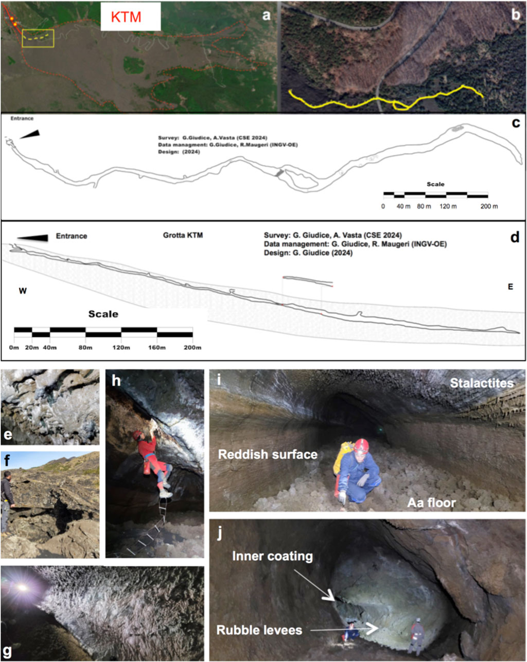
Figure 5. (A) Google map of the 1792–93 eruptive fissure and lava flow field with the path of the Tre Livelli tube displayed by the red line and the two skylight entrances marked by the two yellow circles. The path of the KTM tube is shown with the yellow dotted line and the area magnified in (B) is marked by the yellow rectangle. (B) Google map of the KTM lava tube path shown by the yellow line. (C) Plan view of the KTM lava tube map. (D) Longitudinal section of the KTM lava tube showing the thickness of the lava pile above. The section above the surface refers to the north branch displayed in (C). (E) Photo of the extremely fluid lava coating close to point #7 (see (C)). (F) Photo of the skylight entrance of the KTM tube. (G) Photo showing the grey and fluid coating of the upper half of the tube dribbling down, a small lateral bench, and the reddish surface of the lower half of the wall characteristic of this lava tube. (H) The tube entrance observed from the tube inside, showing the inflation cleft coated by smooth pahoehoe lava, with the floor made of a‘ā clinkers. (I) Photo of the inner coating, with parallel grooves on the roof and lava stalactites. (J) Photo showing a local bend and looking upstream, with a thick inner coating bent over on the upper part, and with the basis buttressed by the rubble levees of the last a‘ā lava flowing inside.
5.2 The Cassone tube
The Cassone tube formed along the path of FL 5 (Figure 3) at ∼ 2.3 km from the main vent, and featured a sustained flow for a substantial time, as testified by the multiple and very thin inner coatings close to the entrance and by the pahoehoe lava flow field extending beyond the end of the tube (Calvari and Pinkerton, 1999). The Cassone tube emplaced in the medial zone of the lava flow field and at its northern margin, where the slope is much lower (∼5°) and inflated flows and tumuli are common, up to ∼200 m in diameter and 10 m thick. The thickness of the lava pile above the tube is very thin, as revealed by the close correspondence between the tube’s inner features and the surface morphology and by the common presence of roots on the tube’s roof, indicating a roof thickness of between 1 and 4 m. The map (Figure 6A) and longitudinal section (Figure 6B) of the Cassone tube are those done with the old survey (Balsamo et al., 1994; Barone et al., 1999) because a collapse at the entrance obstructed the cavity which is no longer accessible. The Cassone tube has a length of ∼250 m and width and height of 4–10 m, and extends in a NE-SW direction (Figures 6A–D). It starts at an ephemeral vent (Figure 6E) that on the surface corresponds to an inflated pahoehoe lobe opened at the base of a large tumulus with central inflation clefts (Figures 6C, D). At the lower end of the tube on the surface to NE there is a shatter ring (Figures 6C, D) that represents the late drainage after having fed several pahoehoe flow lobes downslope (Calvari and Pinkerton, 1999). Despite a relatively constant width (Figure 6A), along the length of the tube the cross-section widens and narrows several times, displaying key-hole sections testifying to flow inflation, ephemeral vent opening at the previous flow front, and vertical tube capture. The last flow inside the tube left a floor with a pahoehoe surface texture only close to the ephemeral vent (Figure 6E), becoming mostly a‘ā for most of the extension of the tube (Figures 6F–H, J). One of the last surges to pass through the tube left very thick inner coatings (5–10 cm thick) that after drainage detached from the walls and rolled over to form the conic structures (Figure 6F). The tube is the result of several flows merged vertically, as can be seen by the key-hole sections testifying to the vertical capture of an upper flow being drained within the lower one (Figure 6G). The ground surface at the time of its emplacement probably had sudden changes in slope that triggered a backward erosion and formed a little lava fall of just 1 m high that can be observed half way (Figures 6A, B, H). Close to the tube entrance the roof is bent down (Figure 6J) as a result of plastic deformation. Close to the entrance the inner lining of the tube is made of several thin coatings, 1–2 mm thick, attesting that the tube had a long life and that several times it was full of fluid lava and drained after the opening of ephemeral vents at its margins, thus feeding the pahoehoe lava flow field observed at its NE lower end on the lava flow field surface. Other features that can be observed inside this tube are lava stalactites close to the entrance, which was probably an old skylight, and lateral benches (Figure 6K) standing half way along the lateral walls and indicating that this tube was active for a long enough time to form these features. Thus, given the size of the tube cross-section and the fact that it was for a long time hosting lava for about half of its height (Figure 6G), it is plausible that this tube was a major feeder of the lava flow field.
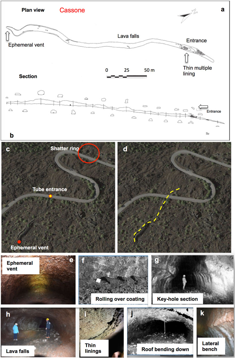
Figure 6. Maps, section and photos of the Cassone tube. (A) Plan view and (B) longitudinal section drawn by Balsamo et al. (1994) and Barone et al. (1999). (C, D) Google maps showing the surface morphology of the lava flow field above the Cassone tube, with the position of the ephemeral vent that generated the tube (full red circle), the tube entrance (yellow circle), the shatter ring beyond the end of the tube (large empty red circle) and the tube’s path (yellow dotted line). (E) Ephemeral vent at the NW end of the tube showing a typical “oven” shape, with a fracture on the ceiling suggesting inflation and embryonic inflation cleft and smooth pahoehoe floor. (F) Right wall of the tube close to the floor of the ephemeral vent in (E), showing thick inner coating detached from the walls and rolled over during the last movement of the flow inside the tube, leaving these conical shapes. Note the white glove for scale and the a‘ā floor. (G) Typical key–hole section (formed by vertical capture of a small upper tube within a lower larger tube; Calvari and Pinkerton, 1999) taken half way within the tube showing vertical capture. (H) Half way along the tube there is a little frozen lava fall evidenced by a smooth and oxidized surface and by a step ∼1 m high. (I) Multiple lining, each about 1 mm thick, observed on the roof close to the tube entrance. (J) Roof of the tube deformed and with a longitudinal fracture attesting plastic deformation. The white tape is 1 m long. (K) Lateral benches with fluid lava coating. Photos (E, H, I, K) are by R. Maugeri, (F, G, J) are by A. Amantia.
5.3 The Coniglio tube
This tube is located at the northern margin of the lava flow field along the FL 5 (Figure 3) and at a distance of ∼2.7 km from the main vent. The lava tube is oriented ∼ N-S and is 98 m long. On the surface, only the upper segment of the tube is represented as an elongated tumulus of pahoehoe with a well-developed central inflation cleft. This inflation cleft is partially collapsed and provides the opening to the cavity (Figure 7). This lobe is part of a wide pahoehoe flow field comprising several lobes extending laterally like fingers (Figure 7A) from the base of a large tumulus. Most of the tube surface is covered by debris and vegetation, being located at the exit of a ravine, and also the floor of the cavity is covered by a thick pile of muddy sediments that conceal the morphology of the floor. The planimetric view (Figure 7B) and longitudinal sections (Figure 7C) are the results of the new survey, whereas the sketch map and transversal sections in Figure 7D are from the old survey (Brunelli and Scammacca, 1975). The Coniglio tube is shallow within the lava flow field, and has a thin roof, as testified by several roots extending within the cavity from the roof fractures, and has the top formed by the upper crust which is up to 5 m thick (Figure 7C). Flow direction inside the tube was from south to north, and the cavity formed by the merging of at least four pahoehoe flow lobes, as can be seen by the four apophysis at the lower end (Figure 7D). The four pahoehoe flow lobes contributed to the inflation of the cavity, which has the inflation cleft at the entrance (Figures 7E, H) and is plastically deformed within the cavity further south (Figure 7F). The merging (horizontal capture; Calvari and Pinkerton, 1999) of a lateral lobe arriving from west and joining the main lava stream is shown by a small cavity standing at a slightly higher level (Figure 7F) that left a ∼1 m high lateral levee and a smooth pahoehoe floor at the junction. Further south, another pahoehoe lobe merged with the main stream (Figure 7G), and after drainage the inner coatings detached from the walls forming two lateral benches joined in the middle. Also here the inflated roof is crossed by a longitudinal fracture colonized by roots and corresponding to the surface inflation cleft.
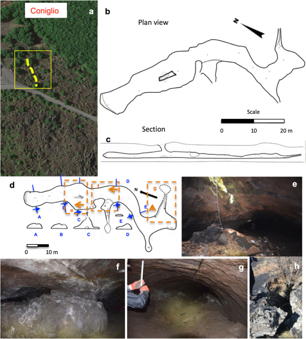
Figure 7. Maps, section and photos of the Coniglio tube. (A) Google Earth map showing the position (yellow square) and direction (yellow dotted line) of the Coniglio tube surrounded by several inflated pahoehoe lava flow lobes with middle inflation clefts. (B) Plan view and (C) longitudinal section (new survey) and (D) old map with transversal sections modified after Brunelli and Scammacca (1975). The directions of the sections are indicated by the blue letters and arrows, the position and viewing directions of the photos (E–G) are indicated by the orange dotted squares and orange arrows. (E) Photo of the entrance from the collapsed roof portion forming inside the cave a thick pile of detritus. (F) Horizontal capture of a lateral pahoehoe lobe into the main stream, with lateral levee, a smooth pahoehoe floor and a longitudinal fracture in the roof. (G) Horizontal capture by a lateral pahoehoe lobe merging into the main stream, with the thick inner coatings detached from the walls and merged together in the middle of the cavity. (H) Tube entrance observed from the surface. Photos (E–H) are by R. Maugeri.
5.4 The Acqua Vitale tube
This is the fourth tube, after the KTM, Cassone and Coniglio tubes, located at the northern margin of the 1792–93 lava flow field and along the FL 5 (Figure 3), at a distance of ∼3.1 km from the main vent. Also this lava tube is very shallow, emplaced partially within an a‘ā and partially within a pahoehoe flow (Figures 8A–C). The tube is oriented N-S and is 178 m long (Table 1), and has two entrances, one from the north and another from the south end, where two collapses offer easy access. The thickness of the tube roof (= lava crust) above is 3–5 m. Using the equation given by Hon et al. (1994), this thickness of the lava crust implies that the tube was active for at least 2.0–5.5 months since, with continuous growth of the crust during emplacement, it implies that the tube was full to the brim for that amount of time. Hence, with this evidence along with its position within the flow field, it seems reasonable to view it as part of the main transport system in the medial sector, at least for lava flow FL 5.
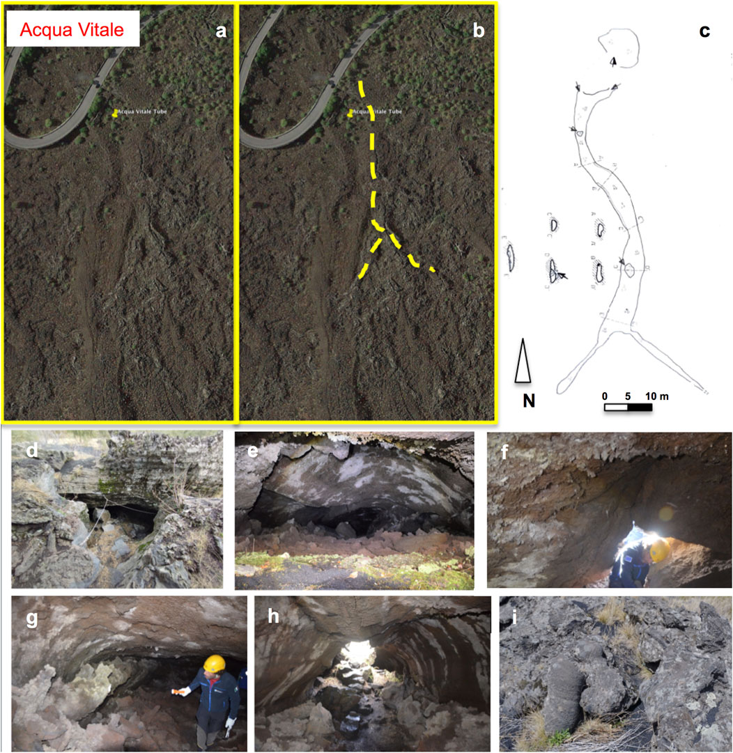
Figure 8. (A) Google Earth map showing the surface morphology of the lava flow field where the Acqua Vitale tube is located, and (B) the same map with the path of the lava tube evidenced by the yellow dotted line. (C) Plan view and transversal sections of the Acqua Vitale tube modified after Barone et al., 1994. (D) North entrance of the tube, showing the inflated a‘ā lava crust (here 2–4 m thick) with inflation clefts. (E) Inner north portion of the tube showing the roof plastically deformed and a longitudinal fracture. Note the a‘ā rubble on the floor. (F) Southern entrance of the tube viewed from the inside showing the upper crust with lava stalactites. (G) Very viscous and thick lateral a‘ā levees inside the tube, upper northern part. (H) Southern part of the cavity, asymmetric where bending SW, with the roof plastically deformed and several massive lava blocks collapsed from the roof. (I) Toothpaste squeeze-outs from the inflation clefts of a tumulus (∼2 m tall) on the ground surface. Photos (D–I) are by R. Maugeri.
The a‘ā lava flow hosting the tube is highly inflated, with central inflation clefts (Figure 8D) from where numerous and large massive blocks detached accumulating on the floor and sides of the cavity (Figure 8E). The inflation clefts on the surface have locally extruded viscous toothpaste lobes ∼50 cm wide (Figure 8F). The highly viscous lava that was transported within this tube is also testified by the rough and high lateral levees left over at the sides of the cavity (Figure 8G) and by the a‘ā surface morphology of the floor (Figure 8H). The inflated and thickened upper crust of the tube formed in many sections sagging (plastically deformed) roof with longitudinal cracks (Figure 8H), locally collapsed to allow access (Figure 8I). The tube is much wider than tall, with the roof going down at places to leave ∼1 m high room and an asymmetric cross-section (Figures 8E, H). This tube is located at the margins of the middle zone of the lava flow field where several large tumuli are located (Figure 3).
5.5 The Mt. Arcimis tubes
The Mt Arcimis lava tubes are a system of braided tubes emplaced mainly within small pahoehoe lava channels extending from the end of FL 3 and to a distance of ∼4.2 km from the main vent (Figure 3, 9). It is a lava tube with two entrances partially closed by a brick wall. The tube comprises four branches (Figures 9A–C), with the south one being the most easily accessible. The roof of the tube has lava stalactites close to the lower entrance and is collapsed in many places (Figures 9A, E). The four branches formed at different topographic levels and times, and reveal a braided flow expanding like a fan. The lava that formed the Mt Arcimis tube system was rather fluid, formed a number of pahoehoe lava channels (Figure 9D), and inflated lobes and tumuli (Figures 9B, C), which are the surface expression of the underground tubes. The four branches numbered in Figure 9B expanded at progressively lower topographic levels, with the branch IV making a small lava fall when joining to branch II; branch I being captured vertically within branch II; and branch II being inflated and later drained within branch III, where eventually also branch IV merged. The inner tube wall in the uppermost and south portion (I) displays vertical striations (Figure 9F) indicating vertical capture through the drainage of the first tube sector to a lower level (II). The second tube branch formed from this to the north (Figure 9A: third arrow top right and beyond), then the third tube branch formed down to the east (III) forming the branch in the lower part of Figure 9A expanding NE. The last branch (IV) is a lateral tributary that on merging to the second (II) and spreading SE formed a small lava fall.
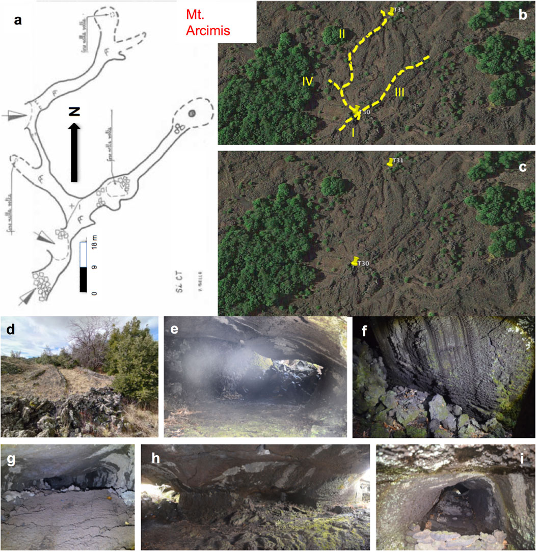
Figure 9. (A) Plan view (modified after Bella et al., 1982) of Mt Arcimis lava tube, with the white and black arrows indicating the entrances. (B) Google Earth map with the yellow dotted lines showing the four branches of the tube, numbered progressively. (C) Google Earth map with the yellow pins showing the position of T30 (initial tumulus) and T31 (final tumulus), respectively connected to the emplacement of this lava tube network. (D) Pahoehoe lava channel, 1–3 m wide, just upslope of the branch I of the Mt Arcimis tube. (E) Southern entrance of the Mt Arcimis tube with collapsed lava blocks obstructing its southern end. (F) Close-up view of the wall on the right of photo (E) showing striations by vertical tube capture. (G) Asymmetric section of the tube inside branch IV with pahoehoe floor. (H) Branch II showing pahoehoe floor, lateral levee where tube bends, and a longitudinal fracture along the roof. (I) Branch III. Photos by R. Maugeri.
5.6 The Morto tube
The Morto lava tube formed within inflated pahoehoe at the distal south-east margins of FL 4 (Figure 3, 10), at a distance of ∼5.1 km from the eruptive fissure. This lava tube is oriented W-E and has not been mapped before. The entrance of the tube (Figures 10A, B) opens as a collapse at the side of the tube and is very narrow, but soon it becomes wider and higher through an inflated chamber (point #2 in the longitudinal section, Figure 11B). The maximum length is 38 m (Table 1), width is 1–4 m, height is 1–2 m, and flow direction is from west to east. The thickness of the lava crust above the tube is up to 5 m, and increases from the western entrance to the eastern end of the tube. The lava tube is located below a pahoehoe lava channel 2–5 m wide with a flat surface. At the entrance, the roof shows lava stalactites (Figure 10D), suggesting us that the flowage within the tube lasted for long enough to allow their formation, and that the entrance collapse was probably a skylight. The floor of the tube is formed by a‘ā clinker, and was probably left over by the last viscous flow that partially drained the cavity and accumulated at its lower end (Figure 10E). The roof lining is a few cm thick (Figure 10F), but close to the entrance a very thick coating (∼0.5–1.0 m thick) partially detached from the roof (Figure 10C) confirms that the last lava occupying the cavity was rather viscous, leaving lateral levees (Figure 10G) partially detached from the walls.
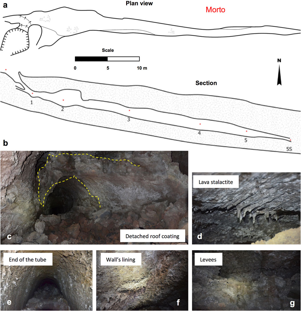
Figure 10. Grotta del Morto lava tube. (A) Plan view and (B) longitudinal section of the lava tube. (C) Inner coating of the roof (marked by the yellow dotted line) up to 1 m thick, partially detached from the roof on the left. (D) Lava stalactites up to 3 cm long on the tube’s roof close to the entrance. (E) End of the tube, showing the a‘ā lava rubble of the floor merging with the roof. (F) Thin lava linings (each ∼ 2–4 mm thick) close to the tube entrance. (G) Lateral a‘ā rubble levees left over by the last a‘ā lava flow travelling within this tube.
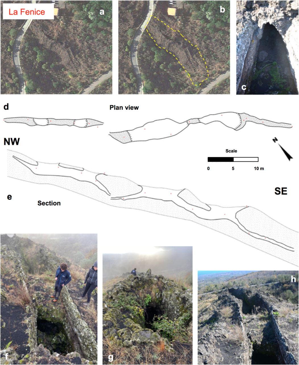
Figure 11. (A, B) Google Earth maps of the surface where the La Fenice lava tube is located, indicated by the yellow dotted outline in (B). (C) Middle portion of the channel where a roof formed, showing two inner coatings ∼5 cm thick. (D) Plan view of the La Fenice lava tube, new map. In white, the cavities, with the indent towards the empty space. (E) Longitudinal section of the La Fenice lava tube. (F) Lava channel partially roofed over in the middle with lateral levees and inner coatings. (G) Middle a‘ā inflated lava flow front collapsed at the front to merge with the flow below by vertical capture, a feature apparently similar to a cinder cone. (H) Middle portion of the La Fenice a‘ā lava tube where a temporary obstruction formed a roof and caused two lateral pahoehoe overflows.
The shape of the tube is simple and it has no lateral branches, indicating that the life of the tube was rather short, coherent with its position at the most advanced part of FL 4 (Figure 3). Inside we have observed only two inner coatings, with the innermost partially detached from the roof, and the outermost much thinner, thus less viscous. These thicknesses are evidence of an increasing viscosity of the lava flowing within the tube, consistent with its distance from the eruptive fissure and with its short life. One section of the tube in the middle has a box shape and a flat roof, apparently related to the flat surface caused by slabby pahoehoe forming the surface of the lava flow. The floor of the tube is an a‘ā that eventually, at the lower end of the tube, obstructs the cavity (Figure 10E).
5.7 The La Fenice tube
At the very end of the lava flow field (∼6.1 km from the eruptive fissure) and along the most distal portion of FL 4 (Figure 3) there is the La Fenice tube, which is a partially sealed a‘ā lava channel, that emplaced on quite a steep slope gradient (∼15°–20°), presumably during the latest stages of lava flow front advance, when cooling increased lava flow viscosity and supply was intermittent. The floor is not visible due to the vegetation. Interestingly enough, this a‘ā lava channel displays lateral pahoehoe overflows, indicating that this channel was at some stage fed by a more fluid lava. This is a 70–m–long a‘ā lava channel partially roofed over in three sections (Figure 11), with evidence of lava stalling at the flow front and overflowing laterally behind an obstruction of the channel. Up to three lava coatings have been detected in the middle half of the channel, with thickness of 4–6 cm, suggesting a rather viscous lava flowing within the channel when compared to the several 1–2 mm thick coatings of the Cassone tube entrance (Calvari and Pinkerton, 1999). The number of coatings within the channel matches with the number of pahoehoe lobes extending beyond the lava flow front, suggesting that each coating is the result of the channel being full of lava and draining once a breakout at the front or margins had drained the flow interior feeding a secondary flow.
The steep ground slope here favoured vertical capture of the inflated a‘ā lava flow front below a previously emplaced flow (Figure 11G), whereas temporary obstructions of the lava channel caused the spreading of thin pahoehoe lava overflows from the two sides of the channel (Figure 11H). This is the second tube located along FL 4 (Figure 3), with the Morto tube being more proximal and La Fenice tube the most distal one.
6 Discussion
6.1 Relationship between lava surface morphology and tube features
Lava tubes have been considered for a long time to form exclusively within pahoehoe lava flows and at low discharge rate (Peterson and Swanson, 1974; Guest et al., 1984; Hallworth et al., 1987), whereas at Etna they are very common also within a‘ā lava flows and with discharge rate spanning three orders of magnitude (Calvari and Pinkerton, 1998; Calvari and Pinkerton, 1999). This apparent discrepancy arises from the observation that the surface of long–lasting lava flows (containing tubes) is commonly characterized by pahoehoe texture, even if during the initial phases of the eruption there were extensive a‘ā flows. In order to unravel the process of lava tube formation also into a‘ā lava flows we need to consider the emplacement of long–lasting lava flow field with its surface textures and tube growth, considering their relationships with discharge rate. Long–lasting effusive eruptions result in the emplacement of complex and compound lava flow fields (Walker, 1978) that may comprise different lava flow morphologies and several lava flow structures (Walker, 1991; Murcia et al., 2014). The common pattern followed by long–lasting effusive eruptions with a supply rate steady enough to produce lava tubes is to show an initial peak in the discharge rate within the first week of the eruption, and a long, slow and gradual decline of the discharge rate until the end (Wadge, 1978; Calvari et al., 1994; Calvari et al., 2003; Harris et al., 2011; Calvari, 2019). The result is the emplacement of arterial a‘ā lava flows during the earlier stages of the eruption causing a significant lengthening of the lava flow field (Kilburn and Lopes, 1988; Kilburn and Lopes, 1991; Mattox et al., 1993). Along these arterial a‘ā flows a master channel and then a tube may form if magma supply is steady for long enough to form a stable cool crust (Greeley, 1987; Calvari and Pinkerton, 1998). If the eruption continues for long enough and there is a decline in the discharge rate, then several ephemeral vents and breakouts may open at the margins of the lava flow field contributing first to its widening and lately to its thickening (Kilburn and Lopes, 1988; Kilburn and Lopes, 1991; Mattox et al., 1993; Pedersen et al., 2017). With the drop in the discharge rate the active vents normally move closer to the eruptive fissure (Mattox et al., 1993; Kauahikaua et al., 1998; Guest et al., 2012), producing a much thicker lava flow field in the proximal to middle part than at its margins (Calvari et al., 1994; Fornaciai et al., 2021). The lower discharge rate leads to formation of small pahoehoe or toothpaste lava lobes oozing from the cracks and fractures of the earlier a‘ā lava flows, that may inflate to form tumuli, and inflation clefts (Walker, 1971; Hon et al., 1994).
Thus, long–lasting effusive eruptions forming complex lava flow fields can display surface features that are not related to the deep-seated lava tubes (Byrnes and Crown, 2001), because the surface records only the last stages of pahoehoe emplaced at low discharge rate during the final stages of the eruption. In addition, the extent to which these small and late pahoehoe flows may enter the former, deeper and more extensive tube system was previously unknown, and in this paper we have shown that even small pahoehoe lobes, when covering inflated a‘ā lava flows whose roof is not completely hardened, might contribute to feed the extensive tube systems formed during the initial phases of the eruption. This process was observed at several locations of the 1792–93 lava flow field, but was especially common within the tubes that developed in the proximal and middle regions of the lava flow field, such as the 3L-KTM and the Cassone tubes (Table 2). Table 2 summarises the main features of the lava tubes described in this paper in order to offer a schematic overview.

Table 2. The main lava tubes of the 1792–93 lava flow field and their most representative features described in this paper. The tube numbers (#) refer to Figure 1C.
6.2 Reconstruction of the lava flow field emplacement
We can reconstruct the pattern of the 1792–93 eruption discharge rate using the maximum length reached by a single flow unit (Walker, 1971; Calvari and Pinkerton, 1998; Wright et al., 2001). Assuming that the initial expansion of the lava flows within the Valle del Bove reached ∼5 km in length in a few days, and using the empirical formula proposed by Calvari and Pinkerton (1998) and published in the correct form by Wright et al. (2001) [L=103.11 E0.47, where L is the final length of the lava flow in meters and E is the mean discharge rate in m3 s-1], we estimate an initial effusion rate of ∼18 m3 s-1. The first flow emplaced when the eruptive fissure crossed the Serra del Salifizio ridge (A; Figure 1C), forming a simple channel and no lava tubes. Considering its size (maximum lava flow length 1.4 km) and using again the same empirical formula (Calvari and Pinkerton, 1998; Wright et al., 2001), it was emplaced at 1.2 m3 s-1. The other possibility is that this flow emplaced at high rate but was volume-limited (Guest et al., 1987; Wright et al., 2001; Applegarth et al., 2010; Rhéty et al., 2017), and stopped when the supply was cut off by the eastward expansion of the eruptive fissure (Recupero, 1815). No tubes formed along this flow, and we relate this to the fact that it was not fed for long enough to allow tube development (Greeley, 1987; Calvari and Pinkerton, 1998; Calvari and Pinkerton, 1999). Finally, hypothesizing that the five arterial flows emplaced from vent B (Figure 1C) as single flow units up to the lower end of the lava flow field for a total length of ∼5 km, the discharge rate of this phase should have increased again up to ∼18 m3 s-1. The most advanced lava flow fronts to the E and SE of this lava flow field were fed by lava tubes (FL 3, FL 4 and FL 5, Figure 3), thus at this stage the discharge rate declined, but the presence of lava tubes allowed the final lava flow field to expand for ∼1.5 km beyond the outline defined by the part emplaced as single flow units. The sequence of lava flows emplacement building up this lava flow field is very similar to the 2014–15 Holuhraun eruption in Iceland described by Pedersen et al. (2017) and to the 1999 Etna eruption that built up the Eastern lava flow field (Calvari et al., 2003).
The flow field fed by the B vent was active for about 1 year, and comprises most of the 1792–93 lava flow field. This extends over an area of ∼5.2 km2, is ∼6.5 km long and 4.5 km wide. During the lengthening of the lava flow field, it is likely that the five arterial a‘ā lava flows emplaced (red dotted arrows in Figure 3), spreading S, SE and E from the eruptive fissure, and possibly following a time sequence from FL 1 to FL 5. The two southernmost flows display an a‘ā channel surface in the most advanced flow fronts (FL 1 and FL 2, Figure 3), indicating that they were probably active for a short time, given that there are no lava tubes along their path. The steep slope of the eruptive fissure favoured the emplacement of a narrow lava channel in the proximal region of the lava flow field that soon roofed over (Calvari and Pinkerton, 1998; Calvari and Pinkerton, 1999) forming the 3L-KTM master tube system. As the lava encountered a gentler slope below the SP 92 road (Figure 3), the advance of the lava slowed down and the flow thickened as a result of both inflation and overlapping of flow lobes. Continuous supply of lava to this region and an accompanying decrease in magma discharge from the vents formed staked tube systems. Merging of flowing lava sometimes occurred when the roof of the previous flow was not completely sealed, and this favoured the vertical capture shown by the key–hole sections and vertical pits joining different levels observed along parts of these tubes (Figure 4B, 5D, 6G; Table 2). Incomplete roof sealing or later collapses caused the two skylights used to access the upper and middle 3L tube (Figure 4B). Another process that might cause the vertical capture is the drainage of the lower tube. In fact, when a lava tube is full, it is pressurized either by lava static pressure or by lava accumulating beneath the crust and causing inflation. This situation provides support to the roof, while maintaining its growth from below (Hon et al., 1994; Thordarson and Self, 1993; Thordarson and Sigmarsson, 2009). At this stage, the roof comprises an upper brittle horizon, weakened by the formation and growth of cooling joints, and a lower viscous/visco-elastic horizon, which has strength enough to hold up the whole roof. As soon as the crust forms, the level of lava within the tube drops (Dragoni et al., 1995), to such an extent that the lava is separated from the roof within some tube-chambers/pools to form a free surface, while it is still in contact with the roof in the chutes. This process results in cooling of the roof above these chambers/pools below the brittle temperature of the lava. The cooling joints extend through the roof and weaken the roof accordingly (e.g., Kauahikaua et al., 1998), enough for it to collapse into the moving lava. This is the process that caused the collapse of the connected a‘ā flow fronts comprising the La Fenice tube. However, based on our observations, it does not matter whether the lava is pahoehoe or a‘ā; the lava always features an inner horizon of viscous/visco-elastic lava that separates the outer solid boundary layer (i.e., the a‘ā rubble or the coherent pahoehoe crust). The difference between this viscous/visco-elastic layer in pahoehoe versus a‘ā is that in the former it becomes the lower part of a stationary crust, while in the latter it has a tendency to move and deform with the flowing lava, carrying the rubble.
Continuous lava supply, a shallower slope, and an inflow into a tube chamber that exceeds the outflow from it (Thordarson, 2000; Duncan et al., 2004; Thordarson and Höskuldsson 2008; Thordarson and Sigmarsson, 2009), promoted the growth of tumuli in the middle portion of the lava flow field, where the KTM tube formed as a prolongation of the 3L, and at least three secondary lava tubes originated: the Cassone, Coniglio and Acqua Vitale tubes (Figures 6–8; Table 2). The Cassone tube corresponds at the surface to an inflated a‘ā lava lobe elongated in an ∼ E-W direction. Of the three, the Cassone tube appears to have been fed for the longest time, as evidenced by the several mm-thick coatings observed at its entrance, where probably also a skylight was located given that the roof is covered by lava stalactites (Corsaro et al., 2005). The lower end of the tube has a shatter ring on the surface (Figure 6C, red circle), likely resulting from the final drainage of the tube that fed several pahoehoe lava flow lobes extending down slope. The prolonged activity of the Cassone tube is consistent with its position half way along FL 5 that was fed in the proximal region by the 3L-KTM tubes, and in the medial region by the Cassone tube. Further east, the Coniglio tube (Figures 3, 7; Table 2) is the result of the lateral merging of several pahoehoe lava flow lobes probably generated by the several tumuli extending in the middle zone of the lava flow field, whereas the Acqua Vitale tube (Figure 8; Table 2) is probably one of the last flows to expand on the flow surface during the latest phases of effusion. In fact, its host lava flow is very thick via inflation, but did not have the ability to expand further down slope. Conversely, the Mt. Arcimis tubes (Figure 9; Table 2) that formed at the eastern end of FL 3 apparently emplaced early during the eruption, when the lava was rather fluid and able to form several pahoehoe lava channels and tumuli branching and merging both laterally and vertically (Figure 9). The Morto and La Fenice lava tubes (Figures 10, 11; Table 2) display an increasing viscosity, with the Morto tube hosted by pahoehoe but displaying a‘ā as the inner floor of the tube. The La Fenice is more a partially roofed over a‘ā lava channel than a real lava tube, consistent with its most advanced position along FL 4 (Figure 3).
The shape and size of the tube network described in this paper is rather different than its Hawai’ian counterpart (Kauahikaua et al., 1998), probably owing to the different eruptive history, eruption duration, magma composition and viscosity, discharge rate and ground slope. The Hawai’ian lava tubes described by Kauahikaua et al. (1998) in the proximal portion of the lava flow field are very big, being typically 3–25 m wide and up to 20 m high, and decreasing in size towards the distal end of the lava flow field, but the depth of active lava flowing within these tubes is very small and rarely deeper than 1–2 m. This observation is explained by Dragoni et al. (1995), who stated that a channeled flow which is slowed down at its upper surface by cooling, must increase its thickness and inflate in order to maintain the same flow rate. Once the lava tube is formed, the initial flow rate can be achieved by a flow thickness smaller than the vertical size of the tube, with the same viscous dissipation (Dragoni et al., 1995). This may explain why under steady state conditions, the lava level inside a tube is frequently lower than the roof of the tube itself (Dragoni et al., 1995). This aspect has important implications when computing an average volumetric discharge rate based on the full size of the lava tubes, which causes overestimated values (Kauahikaua et al., 1998). Conversely at Etna, the proximal lava tubes established within the eruptive fissures and at high ground slope are much deeper than wider, as a result of the narrow arterial flow emplaced on the steep proximal slope (Walker, 1971), channelized and roofed over.
Downcutting or lowering of the tube floor by thermal and/or mechanical erosion is considered common in Hawai’i (Swanson, 1973; Peterson et al., 1994; Kauahikaua et al., 1998; Greeley et al., 1998). On the contrary, definitive proofs of this process on Etna are yet to be found, and only a tentative hypothesis was raised by Greeley (1987) for the aforementioned outcrop of “ghiara” within the 3L tube (Figures 4B,J). Given this outcrop is located within the eruptive fissure, it is possible that the excavation of the ground was caused by the opening of the eruptive fissure rather than by thermal or mechanical erosion of the tube floor by the flowing lava (Calvari and Pinkerton, 1999).
The 3L-KTM tubes are a good representation of the transport system within the proximal sector of the flow fields, at least for the time the lava transport was confined to a closed system (or a thermally insulated system). However, it is worth pointing out once more that the proximal part of the 1792–3 lava was emplaced on significantly steeper slopes (Table 2) than its Hawai’ian counterpart (Kauahikaua et al., 1998) and this is reflected by the shape and size of the tubes sections, much wider than deeper at Hawai’i, and much deeper than wider at Etna (Figures 4, 5).
The Cassone, Coniglio and Acqua Vitale tubes are all in the medial sector of the flow field (Figure 3; Table 2), the first two very close to the flow field edge, while Acqua Vitale is more internal to the field. The first two, Cassone and Coniglio, originating from large tumuli, could possibly comprise the same distributary system originally connected to the 3L-KTM. They probably formed by successive inflation and drainage of interconnected surface flows, as displayed by their longitudinal sections alternating wide chambers and narrow passages (Figures 4B, 5D, 6B, 7C). Each breakout or overflows from skylights might have caused a secondary distributary to deviate from the original pathway, as observed in Hawai’i (Kauahikaua et al., 1998). It is worth noting here that at the end of the Cassone tube there is a pahoehoe flow field, fed by this lava tube, that appears to have been active for a long time (Calvari and Pinkerton, 1999), and that the Coniglio tube is clearly emplaced within several pahoehoe lobes connected together and located a few hundred meters downslope from the Cassone tube (Figure 3; Table 2). By contrast, the Acqua Vitale tube has features displaying a brief life, a short emplacement history, and formed within a rather viscous lava. This could have originated during the thickening phase of the lava flow field and the last stages of its activity.
The last three tubes, Mt. Arcimis, Morto and La Fenice, are all within the distal part of the 1792–3 flow field (Figure 3; Table 2). Of the three, the Mt. Arcimis lava tube is much closer to the eruptive fissure, and comprises a variety of chambers emplaced within pahoehoe flows and internal features suggesting a low viscosity of the host flow, when compared to the Morto and La Fenice tubes and their host flows (Table 2). This is why we hypothesize that the Mt Arcimis tube systems formed earlier during the eruption, but after the high rate peak that probably emplaced FL 1 and FL 2, which display distal lava channels and no tubes (Figure 3). The phase of the eruption that emplaced FL 3 lasted long enough to accumulate ∼90 m thickness lava pile surrounding Mt Arcimis (Recupero, 1815) with a complex system of pahoehoe lava channels, tumuli, and probably many more tubes built within the lava pile than those that we have described here. This activity eventually caused an inversion of the topography confining the successive flows (FL4 and FL5; Figure 3) further north, a situation very similar to the emplacement of the Holuhraun lava flow field (Pedersen et al., 2017), and of the Etna 1999 Eastern flow field (Calvari et al., 2003).
The Morto and La Fenice lava tubes form the lower end of FL 4 (Figure 3), and display features of highly viscous lava (e.g., thick inner coatings; Table 2) and short-lived lava tubes. La Fenice tube, at the very end of the lava flow field, is not even a real tube, but an a‘ā channel partially roofed over, that probably drained thanks to the high slope. However, it allowed the lava flow field to expand further down slope and threaten the town of Zafferana.
These distal lava tubes are very different from their Hawaiian counterpart described by Kauahikaua et al. (1998), where tubes extending beyond the coastline still have the power to erode the substrate. This difference may arise from the different composition, temperature, crystal content and hence viscosity of the lava erupted by Etna and Kilauea.
In this study on the lava tubes emplaced during the 1792–93 eruption, we have shown how the distribution and features of lava tubes, tumuli, channels and others surface morphology features allowed us to reconstruct the emplacement of the lava flow field. In particular, the lack of lava tubes along FL 1 and FL 2 (Figure 3), characterized by a distal morphology of drained channels, suggests that they probably emplaced during the initial stages of the eruption, when the discharge rate was ∼18 m3 s-1 or higher. These two arterial flows most likely acted as obstacles for the southward spreading of lava, and later arterial flows expanded progressively to the north. The third, shorter arterial flow (FL 3, Figure 3) emplaced when discharge rate was lower but lava was still very fluid, giving rise to several pahoehoe lava channels and tumuli forming the lava tube system of Mt. Arcimis (Figure 9; Table 2). These did not expand the lava flow field very much in length, probably because the discharge rate was declining, but significantly increased its thickness, surrounding Mt. Arcimis by a lava pile that locally reached ∼90 m (Recupero, 1815). The decline in discharge rate and the formation of a proximal master tube system (the 3L-KTM) increased the thickness of the lava pile in the middle part of the lava flow field forming several large tumuli feeding secondary lava flows and tubes such as the Cassone, Coniglio and Acqua Vitale. The last and most distal lava tubes along FL 4 (Figure 3) appear to have been the Morto and La Fenice (Figures 10, 11; Table 2), which are very simple, without branching, and probably lasted a short time.
Our results demonstrate that lava tubes during a long–lasting eruption may form at different stages, as soon as the discharge stabilizes, and may give rise to staked tube systems fed by underground processes of tube capture (Calvari and Pinkerton, 1998; Calvari and Pinkerton, 1999). This mechanism has important implication in hazard assessment, because apparently inactive, small pahoehoe surface flows may feed large and distal flow field margins through flowage into deep master tubes.
6.3 Implications for lava flow hazard
The formation and growth of a lava tube system within complex flow fields significantly increases the hazard posed by lava flow expansion, raising the maximum length that a lava flow can attain (Calvari and Pinkerton, 1998). This is mainly due to the insulating effect of the lava tube, allowing lava to cool ∼0.1°C–1.0°C/km (Swanson, 1973; Keszthelyi, 1995; Kauahikaua et al., 1998; Thordarson and Self, 1993) when compared to the cooling of lava free surface within a channel (up to 90°C/km; Bailey et al., 2006; Harris and Rowland, 2009). An example, showing that insulated transport produces by far longer lava flows than open channel flows, is offered by the fact that single flow units within the 1991–93 Etna lava flow field reached 5 km distance at most, whereas lava tube growth within this lava flow field increased this length up to 8.5 km, threatening again the town of Zafferana (Calvari et al., 1994; Calvari and Pinkerton, 1998). Within the 1792–93 lava flow field, the growth of lava tubes probably caused the 5 km long lava flow field to reach the maximum distance of 6.5 km from the vent.
The description of several lava tubes formed within the 1792–93 Etna lava flow field, comprising both pahoehoe and a‘ā morphologies, exemplified how common tube capture is on Etna during long–lasting eruptions. In particular, pahoehoe flows often display horizontal capture by flow lobes merging laterally and sometimes vertically, whereas a‘ā lava flows more often show vertical capture (Table 2). Vertical capture is also common within pahoehoe flow lobes covering a‘ā lava flows whose roof is not yet completely cooled and hardened (Chen et al., 2016), thus allowing late-stage pahoehoe flows to feed deeper and larger tubes or master tubes formed earlier during the eruption. This process might occur completely undetected, because shallow pahoehoe flows captured by an underlying a‘ā flow retain a stationary solidified surface crust and may appear as being no longer fed, while flowage is going on with the pahoehoe fluid interior feeding the a‘ā lava tube below. This underestimated process might contribute to greatly increase the hazard of apparently stopped distal a‘ā lava flow fronts, which may inflate and reactivate by the continuous supply of the fluid interior coming from the late stage pahoehoe flow lobes and apparently stopping on the flow surface after being captured vertically to a deeper level (Figure 12). This was probably also the cause of the late, sudden and unpredicted expansion of the 1991–93 Etna’s lava flow field contained by the earth dam built up at the exit of the Val Calanna, which managed to protect the town of Zafferana for several months (Barberi et al., 1993). However, a secondary effect of the earth dam was to increase lava flow overlapping, with several small pahoehoe flows covering each other, apparently stopping in a few hours, but probably feeding by vertical capture the deep-sited, large tube network extending eastward (Calvari and Pinkerton, 1998) that was eventually threatening Zafferana.
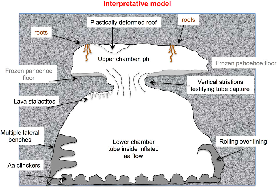
Figure 12. Conceptual model of vertical tube capture between an inflated pahoehoe flow lobe (above) containing an initial tube, and an inflated a‘ā flow (below) with a drained lava tube and several inner features such as lava stalactites, inner linings, lateral benches at different levels, “rolling over” coatings. The upper chamber shows roots penetrating the ceiling across fractures, plastic deformation of the roof, and vertical striations on the walls of the skylight left over where the upper flow merged with the lower one.
6.4 Implications for extraterrestrial environments
Our results are potentially of great interest for the exploration of other planets because of the insulating effect of lava tubes that can protect people from cosmic rays and extreme temperatures, thus offering perfect shelters to human colonies (e.g., Benaroya, 2017). Instead of focusing their efforts only on the exploration of lava tubes extending horizontally at the basis of large pits (e.g., Carrer et al., 2023; Carrer et al., 2024), scientists should also consider the possibility of several stacked chambers, a phenomenon that could be common, especially close to the source vents (Chen et al., 2016). Our results point to the need for further studies on lava flow fields containing lava tubes, possibly extending the exploration using common techniques, for example, very low frequency (VLF) electromagnetic profiles across the single lava tube transporting lava used to determine the cross-sectional area of the molten lava within the tube (Budetta and Del Negro, 1995; Kauahikaua et al., 1996; Al-Oufi et al., 2008). Other emerging techniques might also be useful, such as the electronic total station (Ahn and Hwang, 2008), the electrical resistivity tomography (Al-Amoush and Rajab, 2018), the very high-resolution (VHR) orbital synthetic aperture radar (SAR) imaging systems (Carrer et al., 2023; Carrer et al., 2024), or the microseismic analysis (Torrese et al., 2022) for detecting deep stacked lava tubes within past and still active lava flow fields (e.g., Chappaz et al., 2017). More could be discovered by combining the analysis of lava flow surface morphology with underground surveys of lava tube paths and features.
7 Conclusion
The field survey on the Etna 1792–93 lava flow field and on eight of its major lava tubes revealed the existence of several lava tubes of different size, shape and inner features that were connected to the eruptive processes occurring while the lava flow field was spreading and growing (Table 2). The scientific literature contains several examples of studies carried out during lava tube growth, aimed at reconstructing their process of formation and extent for monitoring and hazard purposes (e.g., Peterson and Swanson, 1974; Mattox et al., 1993; Hon et al., 1994; Peterson et al., 1994; Kauahikaua et al., 1998; James et al., 2012; Orr et al., 2015). However, to the best of our knowledge, this is the first time ever that the distribution of lava tubes and their inner features are used to unravel the emplacement process and growth of a lava flow field. Extending lava tube inner features investigations to just formed lava tubes would help clarify what triggers the process of vertical tube capture and in what conditions it preferentially occurs. In fact, recent effusive eruptions are corroborated by a plethora of information and measurements carried out while the eruption was going on, allowing an ideal connection between the surface processes and those occurring underground. We have reconstructed the discharge rate pattern and a possible sequence of emplacement of the five arterial lava flows described by the contemporary chronicles. We have identified the master tubes (3L-KTM; Figure 3) feeding most of the eruption and located within the eruptive fissure (3L) and in the proximal portion (KTM) of the lava flow field, as well as a secondary distributary (Cassone) responsible for a large pahoehoe lava flow field emplaced on the northern and middle portion of the lava flow field, possibly connected to another system (Coniglio) comprising a few pahoehoe connected chambers. The most advanced lava tubes (Morto and La Fenice) and those formed during the late stage of the eruption (Acqua Vitale) did not manage to expand the flows significantly beyond the lava flow field outline, but caused an increase of ∼1.5 km of the maximum extension of the lava flow field. However, our results demonstrate that horizontal and vertical tube captures are very common processes occurring within long-lasting lava flow fields, with vertical capture involving both pahoehoe and a‘ā flows and representing a significant hazard of reactivation in cases where lava flow fronts have stalled, but inflation is occurring due to continuous supply, and eventually resulting in lateral breakouts.
Data availability statement
The datasets presented in this study can be found in online repositories. The data is publicly available from zenodo, doi: 10.5281/zenodo.11635396).
Author contributions
SC: Conceptualization, Data curation, Formal Analysis, Funding acquisition, Investigation, Methodology, Supervision, Validation, Visualization, Writing–original draft, Writing–review and editing. GG: Data curation, Formal Analysis, Investigation, Methodology, Visualization, Writing–review and editing. RM: Data curation, Formal Analysis, Investigation, Methodology, Visualization, Writing–review and editing. DMe: Data curation, Formal Analysis, Methodology, Writing–review and editing. DMo: Conceptualization, Formal Analysis, Investigation, Supervision, Visualization, Writing–original draft, Writing–review and editing. LM: Investigation, Writing–review and editing. AL: Investigation, Writing–review and editing. LS: Investigation, Writing–review and editing.
Funding
The author(s) declare that financial support was received for the research, authorship, and/or publication of this article. This paper was funded by the project “Understanding lava tube formation and preservation (TUBES)” PRIN2022PNRR, cod. P2022N5C3 - CUPD53D23022910001 European Union-Next generation EU. It also benefitted from funds of the project FIRST - ForecastIng eRuptive activity at Stromboli volcano (Delibera n. 144/2020; Scientific Responsibility: S. C.) INGV-Volcano Department, 2019.
Acknowledgments
We would like to thank M. Cascone, G. Puglisi and R.A. Corsaro for their help in finding the old cave references and maps. We would like to thank Karoly Németh, an anonymous reviewer, and the editor Thor Thordarson for their enthusiastic comments on our paper and for the very useful suggestions, editing and comments that helped us improve a previous version of the manuscript.
Conflict of interest
The authors declare that the research was conducted in the absence of any commercial or financial relationships that could be construed as a potential conflict of interest.
Publisher’s note
All claims expressed in this article are solely those of the authors and do not necessarily represent those of their affiliated organizations, or those of the publisher, the editors and the reviewers. Any product that may be evaluated in this article, or claim that may be made by its manufacturer, is not guaranteed or endorsed by the publisher.
References
Ahn, U. S., and Hwang, S. K. (2008). Interpretation of formation and growth processes of manjang lava tube through detailed surveying with electronic total station. J. Geol. Soc. Korea 44 (5), 657–672.
Al-Amoush, H., and Rajab, J. B. (2018). The use of electrical resistivity tomography to investigate basaltic lava tunnel based on the case study of Al-badia cave in Jordan. Indonesian J. Geoscience 5 (2), 161–177. doi:10.17014/ijog.5.2.161-177
Al-Oufi, A., Mustafa, H. A., Al-Tarazi, E., and Rajab, J. A. (2008). Exploration of the extension of two lava tubes, faults and dikes using very low frequency-electromagnetic technique in NE Jordan. Acta Geophys. 56 (2), 466–484. doi:10.2478/s11600-008-0009-y
Applegarth, L. J., Pinkerton, H., James, M. R., and Calvari, S. (2010). Lava flow superposition: the reactivation of flow units in compound 'a'a flows. J. Volcanol. Geotherm. Res. 194, 100–106. doi:10.1016/j.jvolgeores.2010.05.001
Atkinson, A., and Atkinson, V. (1995). Undara Volcano and its lava tubes. Brisbane, Queensland: Vernon and Anne Atkinson.
Bailey, J. E., Harris, A. J. L., Dehn, J., Calvari, S., and Rowland, S. K. (2006). The changing morphology of an open lava channel on Mt. Etna. Bull. Volcanol. 68, 497–515. doi:10.1007/s00445-005-0025-6
Balsamo, A., Priolo, A., Priolo, G., Sanfilippo, G., and Scammacca, B. (1994). Grotte vulcaniche di Sicilia, notizie catastali: quarto contributo (da Si CT 76 a Si CT 100). Boll. dell'Accademia Gioenia Sci. Nat. Catania 27 (348), 173–212.
Barberi, F., Carapezza, M. L., Valenza, M., and Villari, L. (1993). The control of lava flow during the 1991-1992 eruption of Mt. Etna. J. Volcanol. Geotherm. Res. 56, 1–34. doi:10.1016/0377-0273(93)90048-v
Barone, N., Bonaccorso, R., and Santi, G. (1999). “La Grotta di Cassone,” in “Dentro il vulcano, le grotte dell’Etna”. Centro Speleologico Etneo and ente parco dell'Etna, litografia bracchi, giarre, 294–295.
Barone, N., Priolo, A., Priolo, G., Sanfilippo, G., and Scammacca, B. (1994). Grotte vulcaniche di Sicilia, notizie catastali: terzo contributo (da Si CT 51 a Si CT 75). Boll. Acc. Gioenia Sci. Nat. Catania 27 (346), 367–398.
Bella, V., Brunelli, F., Cariola, A., and Scammacca, B. (1982). Grotte vulcaniche di Sicilia, notizie catastali: secondo contributo (da Si CT 26 a Si CT 50). Atti Accad. Gioenia Sci. Nat. Catania 15 (320), 229–292.
Benaroya, H. (2017). Lunar habitats: a brief overview of issues and concepts. REACH - Rev. Hum. Space Explor. 7–8, 14–33. doi:10.1016/j.reach.2018.08.002
Blair, D. M., Chappaz, L., Sood, R., Milbury, C., Bobet, A., Melosh, H. J., et al. (2017). The structural stability of lunar lava tubes. Icarus 282, 47–55. doi:10.1016/j.icarus.2016.10.008
Brunelli, F., and Scammacca, B. (1975). Grotte Vulcaniche di Sicilia (notizie catastali). Catania: Club Alpino Italiano - Sezione dell'Etna, Gruppo Grotte Catania, 1–85.
Budetta, G., and Del Negro, C. (1995). Magnetic field changes on lava flow to detect lava tubes. J. Volcanol. Geotherm. Res. 65, 237–248. doi:10.1016/0377-0273(94)00108-s
Byrnes, J. M., and Crown, D. A. (2001). Relationships between pahoehoe surface units, topography, and lava tubes at Mauna Ulu, Kilauea Volcano, Hawaii. J. Geophys. Res. 106 (B2), 2139–2151. doi:10.1029/2000jb900369
Calvari, S. (2019). Understanding basaltic lava flow morphologies and structures for hazard assessment. Ann. Geophys. 62 (2). doi:10.4401/ag-8048
Calvari, S., Coltelli, M., Neri, M., Pompilio, M., and Scribano, V. (1994). The 1991-93 Etna eruption: chronology and lava flow field evolution. Acta Vulcanol. 4, 1–14.
Calvari, S., and Liuzzo, M. (1999). Inside volcanoes – IXth international symposium on vulcanospeleology, 46.
Calvari, S., Neri, M., and Pinkerton, H. (2003). Effusion rate estimations during the 1999 summit eruption on Mount Etna, and growth of two distinct lava flow fields. J. Volcanol. Geotherm. Res. 119, 107–123. doi:10.1016/s0377-0273(02)00308-6
Calvari, S., and Pinkerton, H. (1998). Formation of lava tubes and extensive flow field during the 1991-93 eruption of Mount Etna. J. Geophys. Research-Solid Earth 103 (B11), 27291–27302.
Calvari, S., and Pinkerton, H. (1999). Lava tube morphology on Etna and evidence for lava flow emplacement mechanisms. J. Volcanol. Geotherm. Res. 90, 263–280. doi:10.1016/s0377-0273(99)00024-4
Calvari, S., Giudice, G., Maugeri, R., Messina, D., Morgavi, D., Miraglia, L., et al. (2024). Complex Lava Tube networks developed within the 1792-1793 Lava Flow Field on Mount Etna (Italy): Insights for hazard assessment. Supporting Informations: Maps and sections of the lava tubes. doi:10.5281/zenodo.11635396
Carrer, L., Castelletti, D., Pozzobon, R., Sauro, F., and Bruzzone, L. (2023). A novel method for hidden natural caves characterization and accessibility assessment from spaceborne VHR SAR images. IEEE Trans. Geosci. Rem. Sens. 61, 1–11. doi:10.1109/tgrs.2022.3222991
Carrer, L., Pozzobon, R., Sauro, F., Castelletti, D., Patterson, G. W., and Bruzzone, L. (2024). Radar evidence of an accessible cave conduit on the Moon below the Mare Tranquillitatis pit. Nat. Astron. doi:10.1038/s41550-024-02302-y
Chappaz, L., Sood, R., Melosh, H. J., Howell, K. C., Blair, D. M., Milbury, C., et al. (2017). Evidence of large empty lava tubes on the Moon using GRAIL gravity. Geophys. Res. Lett. 44, 105–112. doi:10.1002/2016GL071588
Chen, Z., Liu, Y., Wei, H., Xu, J., and &Guo, W. (2016). Tube coalescence in the Jingfudong lava tube and implications for lava flow hazard of Tengchong volcanism. Int. J. Speleology 45 (3), 219–229. doi:10.5038/1827-806X.45.3.1987
Corsaro, R., Giudice, G., and Puglisi, G. (1995). “Il sistema 3 livelli - ktm: studio comparato di una colata con gallerie di scorrimento lavico,” in Atti del 1° Convegno Regionale di Speleologia della Sicilia. Ragusa.
Corsaro, R. A., Calvari, S., and Pompilio, M. (2005). Formation of lava stalactites in the master tube of the 1792-1793 flow field. Mt. Etna. Am. Mineralogist 90, 1413–1421.
Dragoni, M., Piombo, A., and Tallarico, A. (1995). A model for the formation of lava tubes by roofing over a channel. J. Geophys. Res. 100 (B5), 8435–8447. doi:10.1029/94jb03263
Duncan, A. M., Guest, J. E., Stofan, E., Anderson, S., Pinkerton, H., and Calvari, S. (2004). Development of tumuli in the medial portion of the 1983 aa flow-field, Mount Etna, Sicily. J. Volcanol. Geotherm. Res. 132, 173–187. doi:10.1016/S0377-0273(03)00344-5
Fornaciai, A., Andronico, D., Favalli, M., Spampinato, L., Branca, S., Lodato, L., et al. (2021). The 2004-2005 Mt. Etna compound lava flow field: a retrospective analysis by combining remote and field methods. J. Geophys. Res. Solid Earth 126, e2020JB020499. doi:10.1029/2020JB020499
Gemmellaro, C. (1858). La vulcanologia dell'Etna - La topografia, la geologia, la storia delle sue eruzioni, la descrizione e lo esame de' fenomeni vulcanici. Catania: Tipografia dell'Accademia Gioenia di C.
Gottini, V., Rizzo, S., and Sturiale, C. (1980). I fenomeni eruttivi dell'Etna nel secolo XVIII. Atti Accad. Gioenia Di Sci. Nat. Catania 12 (VII), 67–79.
Greeley, R. (1987). The role of lava tubes in Hawaiian volcanoes. U.S.G.S Prof. Pap. 1350 (2), 1589–1606.
Greeley, R., Fagents, S. A., Harris, R. S., Kadel, S. D., Williams, D. A., and Guest, J. E. (1998). Erosion by flowing lava: field evidence. J. Geophys. Res. 103 (B11), 27325–27345. doi:10.1029/97jb03543
Guest, J. E., Duncan, A. M., Stofan, E. R., and Anderson, S. W. (2012). Effect of slope on development of pahoehoe flow fields: evidence from Mount Etna. J. Volcanol. Geotherm. Res. 219–220, 52–62. doi:10.1016/j.jvolgeores.2012.01.006
Guest, J. E., Kilburn, C. R. J., Pinkerton, H., and Duncan, A. M. (1987). The evolution of lava flow-fields: observations of the 1981 and 1983 eruptions of Mount Etna, Sicily. Bull. Volcanol. 49, 527–540. doi:10.1007/bf01080447
Guest, J. E., Wood, C., and Greeley, R. (1984). Lava tubes, terraces and megatumuli on the 1614–24 pahoehoe lava flow field, Mount Etna, sicily. Bull. Volcanol. 47 (3), 635–648. doi:10.1007/bf01961232
Hallworth, M. A., Huppert, H. E., and Sparks, R. S. J. (1987). A laboratory simulation of basaltic lava flows. Mod. Geol. 11, 93–107.
Harris, A. J. L., Dehn, J., and Calvari, S. (2007). Lava effusion rate definition and measurement: a review. Bull. Volcanol. 70, 1–22. doi:10.1007/s00445-007-0120-y
Harris, A. J. L., and Rowland, S. K. (2009). “Effusion rate controls on lava flow length and the role of heat loss: a review. From,” in Studies in volcanology: the legacy of george walker. Special publications of IAVCEI. Editors T. Thordrson, S. Self, G. Larsen, S. K. Rowland, and A. Hoskuldsson (London: Geological Society), 33–51.
Harris, A. J. L., Rowland, S. K., Villeneuve, N., and Thordarson, T. (2017). Pāhoehoe, ‘a‘ā, and block lava: an illustrated history of the nomenclature. Bull. Volcanol. 79, 7. doi:10.1007/s00445-016-1075-7
Harris, A. J. L., Steffke, A., Calvari, S., and Spampinato, L. (2011). Thirty years of satellite-derived lava discharge rates at Etna: implications for steady volumetric output. J. Geophys. Res. 116, B08204. doi:10.1029/2011JB008237
Hon, K., Kauahikaua, J., Denlinger, R., and Mackay, K. (1994). Emplacement and inflation of pahoehoe sheet flows: observations and measurements of active lava flows on Kilauea Volcano, Hawaii. Geol. Soc. Am. Bull. 106, 351–370. doi:10.1130/0016-7606(1994)106<0351:eaiops>2.3.co;2
Hroarsson, B., and Jonsson, S. S. (1991). “Lava caves in the hallmundarhraun lava flow, western Iceland,” in 6th International Symposium on Vulcanospeleology, Hilo, Hawaii, August 1991, 85–88.
James, M. R., Applegarth, L. J., and Pinkerton, H. (2012). Lava channel roofing, overflows, breaches and switching: insights from the 2008–2009 eruption of Mt. Etna. Bull. Volcanol. 74, 107–117. doi:10.1007/s00445-011-0513-9
Jonsson, S. S., and Hroarsson, B. (1991). “Preliminary speleological investigations in Surtsey,” in 6th International Symposium on Vulcanospeleology, Hilo, Hawaii, August 1991, 89–94.
Kauahikaua, J., Cashman, K. V., Mattox, T. N., Heliker, C. C., Hon, K. A., Mangan, M. T., et al. (1998). Observations on basaltic lava streams in tubes from Kilauea Volcano, island of Hawaii. J. Geophys. Res. 103 (B11), 27303–27323. doi:10.1029/97jb03576
Kauahikaua, J., Mangan, M., Heliker, C., and Mattox, T. (1996). A quantitative look at the demise of a basaltic vent: the death of Kupaianaha, Kilauea Volcano, Hawai‘i. Bull. Volcanol. 57, 641–648. doi:10.1007/s004450050117
Kempe, S., Henschel, H.-V., Shick, H., and Trusdell, F. (2006). Geology and genesis of the kamakalepo cave system in mauna loa picritic lavas, Na'alehu, Hawaii. Assoc. Mexican Cave Stud. Bull. 19, 229–242.
Keszthelyi, L. (1995). A preliminary thermal budget for lava tubes on the Earth and planets. J. Geophys. Res. 100 (20), 20411–20420. doi:10.1029/95jb01965
Kilburn, C. R. J. (1990). “Surfaces of aa flow-fields on Etna, Sicily: morphology, rheology, crystallization and scaling phenomena,” in IAVCEI Proceedings in Volcanology. Vol. 2, Lava flows and domes: emplacement mechanisms and hazard implications. Editor J. H. Fink (Berlin: Springer), 129–156.
Kilburn, C. R. J. (1993). “Lava crusts, aa flow lengthening and the pahoehoe-aa transition,” in Active lavas: monitoring and modelling. Editors C. R. J. Kilburn, and G. Luongo (London: UCL Press), 263–279.
Kilburn, C. R. J., and Guest, J. E. (1993). “Aa lavas of Mount Etna, sicily,” in Active lavas: monitoring and modelling. Editors C. R. J. Kilburn, and G. Luongo (London: UCL Press), 73–105. doi:10.4324/9781003325178
Kilburn, C. R. J., and Lopes, R. M. C. (1988). The growth of aa lava flow fields on Mount Etna, Sicily. J. Geophys. Res. 93 (B12), 14759–14772. doi:10.1002/9781118782064.ch26
Kilburn, C. R. J., and Lopes, R. M. C. (1991). General patterns of flow field growth: aa and blocky lavas. J. Geophys. Res. 96 (B12), 19721–19732. doi:10.1029/91jb01924
Lanzafame, G., Mollo, S., Iezzi, G., Ferlito, C., and Ventura, G. (2013). Unraveling the solidification path of a pahoehoe “cicirara” lava from Mount Etna volcano. Bull. Volcanol. 75, 703. doi:10.1007/s00445-013-0703-8
Lipman, P. W., and Banks, N. G. (1987). “Aa flow dynamics, mauna loa 1984,” in Volcanism in Hawaii (Washington: USGS Professional Paper), 1350, 1527–1567.
Lyell, C. (1858). On the structure of lavas which have consolidated on steep slopes; with remarks on the mode of origin of Mount Etna, and on the theory of “craters of elevation”. Phil. Trans. 148, 703–786+904.
Mancini, F., Dubbini, M., Gattelli, M., Stecchi, F., Fabbri, S., and Gabbianelli, G. (2013). Using unmanned aerial vehicles (UAV) for high-resolution reconstruction of topography: the structure from motion approach on coastal environments. Remote Sens. 5, 6880–6898. doi:10.3390/rs5126880
Martin, R. P., and Benaroya, H. (2023). Pressurized lunar lava tubes for habitation. Acta Astronaut. 204, 157–174. doi:10.1016/j.actaastro.2022.12.013
Mattox, T. N., Heliker, C., Kauahikaua, J., and Hon, K. (1993). Development of the 1990 kalapana flow field, Kilauea volcano, Hawaii. Bull. Volcanol. 55, 407–413. doi:10.1007/bf00302000
Murcia, H., Németh, K., Moufti, M. R., Lindsay, J. M., El-Masry, N., Cronin, S. J., et al. (2014). Late Holocene lava flow morphotypes of northern Harrat Rahat, Kingdom of Saudi Arabia: implications for the description of continental lava fields. J. Asian Earth Sci. 84, 131–145. doi:10.1016/j.jseaes.2013.10.002
Németh, K., and Moufti, M. R. (2023). Lava flow hazard and its implication in geopark development for the active harrat khaybar intracontinental monogenetic volcanic field, Saudi Arabia. Land 12, 705. doi:10.3390/land12030705
Orr, T. (2011). Lava tube shatter rings and their correlation with lava flux increases at Kilauea Volcano, Hawai‘i. Bull. Volcanol. 73, 335–346. doi:10.1007/s00445-010-0414-3
Orr, T. R., Bleacher, J. E., Patrick, M. R., and Wooten, K. M. (2015). A sinuous tumulus over an active lava tube at Kilauea Volcano: evolution, analogs, and hazard forecasts. J. Volcanol. Geotherm. Res. 291, 35–48. doi:10.1016/j.jvolgeores.2014.12.002
Pedersen, G. B. M., Höskuldsson, A., Durig, T., Thordarson, T., Jónsdóttir, I., Riishuus, M. S., et al. (2017). Lava field evolution and emplacement dynamics of the 2014–2015 basaltic fissure eruption at Holuhraun, Iceland. J. Volcanol. Geotherm. Res. 340, 155–169. doi:10.1016/j.jvolgeores.2017.02.027
Peterson, D. W., Holcomb, R. T., Tilling, R. I., and Christiansen, R. L. (1994). Development of lava tubes in the light of observations at mauna ulu, Kilauea volcano, Hawaii. Bull. Volcanol. 56, 343–360. doi:10.1007/s004450050044
Peterson, D. W., and Swanson, D. A. (1974). Observed formation of lava tubes during 1970-71 at Kilauea Volcano, Hawaii. Stud. Speleol. 2, 209–222.
Pijl, A., Tosoni, M., Roder, G., Sofia, G., and Tarolli, P. (2019). Design of terrace drainage networks using UAV-based high-resolution topographic data. Water 11, 814. doi:10.3390/w11040814
Recupero, G. (1815). “Storia naturale e generale dell'Etna,” in Literary remains by A. Recupero, 2 volumes, Catania.
Rhéty, M., Harris, A., Villeneuve, N., Gurioli, L., Médard, E., Chevrel, O., et al. (2017). A comparison of cooling-limited and volume-limited flow systems: Examples from channels in the Piton de la Fournaise April 2007 lava-flow field. Geochem. Geophys. Geosystems 18, 3270–3291. doi:10.1002/2017gc006839
Rossi, M. J. (1996). Morphology and mechanism of eruption of postglacial shield volcanoes in Iceland. Bull. Volcanol. 57, 530–540. doi:10.1007/s004450050110
Santi, G. (1999). “La Grotta dei Tre Livelli,” in “Dentro il vulcano, le grotte dell’Etna”. Centro Speleologico Etneo and ente parco dell'Etna (Litografia Bracchi, Giarre: Publisher), 286–289.
Self, S., Keszthelyi, L., and Thordarson, T. (1998). The importance of pahoehoe. Annu. Rev. Earth Planet. Sci. 26, 81–110. doi:10.1146/annurev.earth.26.1.81
Stephenson, P. J., Burch-Johnston, A. T., Stanton, D., and Whitehead, P. W. (1998). Three long lava flows in north Queensland. J. Geophys. Res. 103, 27359–27370
Swanson, D. A. (1973). Pahoehoe flows from the 1969-1971 mauna ulu eruption, Kilauea volcano, Hawaii. Geol. Soc. Am. Bull. 84, 615–626. doi:10.1130/0016-7606(1973)84<615:pfftmu>2.0.co;2
Tanguy, J. C. (1981). Les éruptions historiques de l’Etna: chronologie et localisation. Bull. Volcanol. 44 (3), 585–640. doi:10.1007/bf02600588
Thordarson, T. (2000). Physical volcanology of Surtsey, Iceland: a preliminary report. Surtsey Res. 11, 109–126. doi:10.33112/surtsey.11.14
Thordarson, T., and Self, S. (1993). The Laki (skaftar fires) and grimsvotn eruptions in 1783-1785. Bull. Volcanol. 55, 233–263. doi:10.1007/bf00624353
Thordarson, T., Self, S., Miller, D. J., Larsen, G., and Vilmundardottir, E. G. (2003). “Sulphur release from flood lava eruptions in the Veidivotn, Grimsvotn and Katla volcanic systems, Iceland,” in Volcanic degassing. Editors C. Oppenheimer, D. M. Pyle, and J. Barclay (London: Geol. Soc. London, Spec. Publ.), 213, 103–121.
Thordarson, T., and Sigmarsson, O. (2009). “Effusive activity in the 1963–1967 Surtsey eruption, Iceland: flow emplacement and growth of small lava shields,” in Studies in volcanology: the legacy of george walker. Special publications of IAVCEI. Editors T. Thordarson, S. Self, G. Larsen, S. K. Rowland, and A. Hoskuldsson (London: Geological Society), 53–84.
Tomasi, I., Massironi, M., Meyzen, C. M., Pozzobon, R., Sauro, F., Penasa, L., et al. (2022). Inception and evolution of La corona lava tube system (Lanzarote, canary Islands, Spain). J. Geophys. Research- Solid Earth 127, e2022JB024056. doi:10.1029/2022JB024056
Torrese, P., Unnitham, V., and Rossi, A. P. (2022). Planetary analogue study using microseismic analysis for near-surface lava tube detection and exploration. Icarus 377, 114912. doi:10.1016/j.icarus.2022.114912
Wadge, G. (1978). Effusion rate and the shape of aa lava flow-fields on Mount Etna. Geology 6, 503–506. doi:10.1130/0091-7613(1978)6<503:eratso>2.0.co;2
Wadge, G. (1981). The variation of magma discharge during basaltic eruptions. J. Volcanol. Geotherm. Res. 11, 139–168. doi:10.1016/0377-0273(81)90020-2
Walker, G. P. L. (1967). Thickness and viscosity of etnean lavas. Nature 213, 484–485. doi:10.1038/213484a0
Walker, G. P. L. (1971). Compound and simple lava flows and flood basalts. Bull. Volcanol. 35 (2), 579–590. doi:10.1007/bf02596829
Walker, G. P. L. (1991). Structure, and origin by injection of lava under surface crust of tumuli, “lava rises”, “lava-rise pits”, and “lava-inflation clefts” in Hawaii. Bull. Volcanol. 53 (7), 546–558. doi:10.1007/bf00298155
Westoby, M. J., Brasington, J., Glasser, N. F., Hambrey, M. J., and Reynolds, J. M. (1012). “Structure-from-Motion” photogrammetry: a low-cost, effective tool for geoscience applications. Geomorphology 179, 300–314. doi:10.1016/j.geomorph.2012.08.021
Woo, K. S., Kim, L., Ji, H., Jeon, Y., Ryu, C. G., and Wood, C. (2019). Geological heritage values of the yongcheon cave (lava tube cave), Jeju island, Korea. Geoheritage 11, 615–628. doi:10.1007/s12371-018-0315-y
Keywords: lava tubes, lava flows, Etna volcano, lava flow fields, lava tube networks, horizontal and vertical tube capture, pahoehoe and a‘ā lavas
Citation: Calvari S, Giudice G, Maugeri R, Messina D, Morgavi D, Miraglia L, La Spina A and Spampinato L (2024) Complex lava tube networks developed within the 1792–93 lava flow field on Mount Etna (Italy): insights for hazard assessment. Front. Earth Sci. 12:1448187. doi: 10.3389/feart.2024.1448187
Received: 12 June 2024; Accepted: 28 August 2024;
Published: 18 September 2024.
Edited by:
Thorvaldur Thordarson, University of Iceland, IcelandReviewed by:
Jan Marie Lindsay, The University of Auckland, New ZealandKaroly Nemeth, Institute of Earth Physics and Space Science (EPSS), Hungary
Copyright © 2024 Calvari, Giudice, Maugeri, Messina, Morgavi, Miraglia, La Spina and Spampinato. This is an open-access article distributed under the terms of the Creative Commons Attribution License (CC BY). The use, distribution or reproduction in other forums is permitted, provided the original author(s) and the copyright owner(s) are credited and that the original publication in this journal is cited, in accordance with accepted academic practice. No use, distribution or reproduction is permitted which does not comply with these terms.
*Correspondence: S. Calvari, sonia.calvari@ingv.it
†ORCID: Sonia Calvari, orcid.org/0000-0001-8189-5499; Gaetano Giudice, orcid.org/0000-0002-9410-4139; Roberto Maugeri, orcid.org/0000-0003-4330-3434; Danilo Messina, orcid.org/0009-0005-2855-2637; Daniele Morgavi, orcid.org/0000-0002-2858-1586; Lucia Miraglia, orcid.org/0000-0001-9383-7683; Alessandro La Spina, orcid.org/0000-0002-5007-613X; Letizia Spampinato, orcid.org/0000-0002-0809-9135