 Tong Li
 Ming Chen3
- 1Yellow River Institute of Hydraulic Research, YRCC, Zhengzhou, China
- 2Research Center on Levee Safety and Disaster Prevention, MWR, Zhengzhou, China
- 3State Key Laboratory of Water Resources and Hydropower Engineering Science, Wuhan University, Wuhan, China
The fragmentation size distribution is an important index to evaluate blasting effect. Based on stress wave theory, a blasting fragmentation distribution model is established, and the key influencing factors were clarified. Then, the distribution characteristics of rock fragmentation in water-coupled blasting and air-coupled blasting were compared and verified by numerical simulation and field test. The results show that the rock blasting fragmentation size is negatively correlated with borehole pressure and unit explosive consumption when blasting rock is determined. The existence of water slows down the attenuation of blasting load, prolongs the duration, and makes the blasting pressure transmitted to hole wall significantly greater than air-coupled one, which is equivalent to increasing the unit explosive consumption. Moreover, the rock fracture development speed and fragmentation degree of water-coupled blasting is significantly higher than air-coupled blasting. Comprehensively determined in same charging parameters, water-coupled blasting compared with air-coupled blasting can improve the degree of rock fragmentation, the average size of rock after blasting is smaller, more uniform particle size distribution. The research results for the control of blasting and optimization of explosive energy utilization have important reference significance.
1 Introduction
Compared with coupling charge, the decoupling charge can effectively reduce the borehole pressure, the excessive crushing of rock, so that more explosive energy can be used for crushing and throwing of rock mass, thus improving the blasting effect. It is the most commonly used charge structure in engineering site (Sher and Aleksandrova, 2007; Ye et al., 2017). Water-coupled blasting and air-coupled blasting refer to the blasting methods in which water or air is used as the coupling medium to fill the gap between the explosive and the borehole wall when the charge is decoupled. Air and water, as common coupling media in radial decoupling charge blasting, have different physical properties and dynamic characteristics in improving the explosive energy transfer and blasting effect (Wang et al., 2020; Shi et al., 2022). Considering that different blasting operations have different requirements on rock blasting fragmentation size, the most commonly used bench blasting is taken as an example, study on the influence of different coupling media on fragmentation characteristics.
Scholars at home and abroad have done a lot of researches on the fragmentation size distribution of rock blasting. Dai et al. (2008) deduced the relationship between fragmentation size distribution and blast borehole pressure through theory, and pointed out that the explosive velocity and unit explosive consumption are the key factors affecting rock fragmentation. Jiang et al. (2015) optimized the relationship between unit explosive consumption and bulk rate and small block rate in rock blastability classification, and identified the improvement direction of optimization of block distribution. Yu et al. (2021) determined the influence characteristics of delay time on spatial distribution of blasting fragmentation by blasting tests, and studied the influence of delay time on various indexes such as different particle size and average size of rock fragmentation. Katsabanis et al. (2020) found that the delay time and complex stress wave interaction in basting play an important role in fracture distribution through damage calculation. Chi et al. (2019) studied the effects of decoupling coefficient, free surface and boundary conditions on blasting fragmentation distribution through small-scale blasting tests of rock cylinders.
In terms of research on the change of rock blasting breakage caused by difference of charge structure, Melnikov (1962) believes that a large part of the explosive energy transferred into rock mass is consumed in crushing zone, which reduces the energy utilization rate of rock breaking. Changing charge structure to control the scope of excessive crushing zone is helpful for optimizing the rock blasting breakage effect. It is of great significance to improve the effective utilization rate of explosive energy. Moxon et al. (1993) and Mead et al. (1993) explored the influence of air interval charge on rock breakage, and the test results showed that air interval charge can change rock fragmentation distribution, and the average fragmentation distribution is directly related to the proportion of air intervals. Based on this study, Liu and Katsabanis (1996) determined the optimal air interval through numerical simulation. Yin et al. (2021) put forward the air interval charging structure at the top of high bench blasting, and research shows that it can improve the bottom rock crushing effect. Jang et al. (2018) pointed out that local rock mass fragmentation can be strengthened by adjusting the distribution position of water in borehole, and therefore proposed water-cushion blasting, which effectively improved the stress distribution in borehole bottom area and reduced the generation of blasting toe. Huang et al. (2014) compared the concrete blasting excavation under complex environment, and believed that water-coupled blasting could give consideration to blasting safety and excavation efficiency. Yan and Yu (2009) compared the rock failure characteristics caused by air-coupled blasting and water-coupled blasting under different charge coefficients, and pointed out the matching relationship between excavation demand and charge structure selection. Yang et al. (2019) studied the changes of stress field in rock mass during blasting with different coupling media through high-speed camera technology, and the results showed that differences in coupling media led to differences in explosive energy transfer efficiency. Wang et al. (2008) and Wang and Li (2005) analyzed the shock wave intensity characteristics in rock induced by blasting under coupled blasting, air-coupled blasting and water-coupled blasting, and showed that reasonable decoupling coefficient could reduce or even disappear the crushing zone range, thus reducing the proportion of small and medium particles in rock fragmentation size distribution after blasting.
At present, the analysis of the influence of borehole coupling medium on fragmentation distribution characteristics of rock blasting is mostly limited to a certain medium or different charge forms with same medium, and the analysis of different coupling medium is not involved. Through theoretical analysis, combined with numerical simulation and field test, this paper will explore the influence of coupling medium changes on rock blasting fragmentation size, and make accurate and scientific evaluation of the difference between two-coupling media, which has important guiding significance for the control and utilization of water-coupled blasting.
2 Influencing factors of rock fragmentation size in bench blasting
Joints and cracks in rock mass develop, and the expansion and convergence of internal cracks under the action of blasting load led to rock mass fracture. Grady (1982) deduced the average fragmentation size of rock mass under brittle fracture conditions based on energy balance theory:
Where △d represents the average fragmentation size; KIC represents the rock fracture toughness; ρc represents the rock wave impedance;
According to Grady model, the rock fragmentation size distribution is directly related to particle strain rate. Under the action of explosion, the borehole wall particles produce extremely high velocity and pressure value in a short time, and initially radiate outward in the form of high-intensity and strong discontinuity shock wave. With the viscous energy dissipation, the destruction energy dissipation and the diffusion of wave (Dong et al., 2006), the shock wave velocity and pressure decrease and gradually decay into stress wave. Under the application of high intensity shock wave and detonation gas, rock mass will produce strong dynamic response. At present, strain rate and load rate are mainly used to measure the degree of dynamic application of materials, especially the strain rate parameter, which directly reflects the dynamic response of materials (Xie et al., 2023). Due to the difficulty in measuring the strain rate of rock near borehole, it is difficult to measure the spatio-temporal variation of strain rate. Therefore, based on the cylindrical wave displacement comodulation equation, the correlation between radial strain rate and vibration velocity in column coordinate system is introduced (Wei et al., 2021):
Where
According to wave theory, stress waves propagating in medium should satisfy the mass and momentum equations.
Where subscript 0 represents parameters before disturbance, and the rest are parameters after disturbance; P, ρ, v and D represent the pressure, density, particle velocity and propagation velocity of shock wave, respectively.
There is a certain relationship between the shock wave propagation velocity and the particle velocity, that is, the Hugoniot equation applicable to rock mass:
Where a and b represent parameters related to lithology, a represents equivalent to the propagation velocity of sound wave in rock mass, b=1∼1.5.
By combining Eqs 3–5, the initial particle vibration velocity vr0 of borehole wall can be obtained as:
Where Pr0 represents the peak pressure of borehole wall, and its calculation method has been determined by many scholars (Chen et al., 2020; Ye et al., 2021).
At present, the attenuation propagation of shock wave and stress wave is usually studied theoretically and simulated numerically. The exponential attenuation formula can better reflect the propagation law of shock wave and stress wave, namely (Zhang et al., 1990):
Where vr represents the peak radial particle velocity at the distance from borehole center r in column coordinate system, α represents the shock wave or stress wave decay index, α=1.5∼3, r0 represents the borehole radius, r represents the distance between the particle and the borehole center (m).
By combining Eqs 2, 6, 7, the variation rule of rock mass strain rate near borehole under column coordinate system is introduced, and the following results are obtained:
Combined Eqs (1, 8) can obtain:
In Eq. 9 where KIC, ρc, a, b are all parameters related to lithology, which are mainly determined by blasting medium itself. When the blasting medium is determined, the influence of blasting parameters is mainly concentrated on the peak borehole pressure Pr0, and the two are negatively correlated, that is, the greater the peak borehole pressure, the smaller the rock fragmentation size.
In engineering blasting, it is easier to change the blasting load on rock by changing charge structure, so as to meet the requirements of different engineering purposes. At the same time, different charge decoupling values can be adopted to realize different blasting charge amounts under constant hole diameter, and then the rock can be subjected to different explosion load values. Dai Jun et al. research shows that there is a following relationship between explosive charge and rock fragmentation size:
Where vc represents the charge volume, ρe represents the explosive density, α = 1.5∼3, q represents the borehole charge, γ represents the pressure expansion attenuation index of detonation product.
According to Eq. 10, there is a negative correlation between the rock fragmentation size and the unit explosive consumption, that is, the greater the explosive consumption, the smaller the rock fragmentation size.
3 The difference of fragmentation characteristics in bench blasting with different coupling media
3.1 Difference induced by changes in borehole pressure
For blasting with different coupling media, the borehole pressure has been determined by many scholars, and the calculation process is not detailed in this paper. Based on the distribution of rock mass types, commonly used blasting parameters and industrial explosive types in actual excavation, taking emulsion explosive blasting in siltstone, limestone and granodiorite three kinds of rock mass with obvious difference in strength properties as an example, a comparative analysis of blasting borehole pressure of two coupling media with typical charging structure is carried out. The unit volume explosive heat of emulsion explosive (ρe=1300 kg/m3, D=4000 m/s) is 4.192e9J/m3. The calculated rock mechanics parameters are shown in Table 1, and the calculated results are shown in Figure 1.
Table 1. Table of calculated rock mass mechanical parameters.
Figure 1. Peak borehole pressure of blasting with different coupling media.
As can be seen from Figure 1, due to large flow viscosity and low compressibility of water compared with air, the shock wave weakens slowly during water-coupled blasting, and the explosion pressure delivered to borehole wall is significantly greater than air-coupled blasting. Combined with above analysis, when blasting medium is determined, the rock average fragmentation size by blasting is negatively correlated with the peak borehole pressure. The greater peak borehole pressure, the smaller rock fragmentation size. It can be concluded that compared with air-coupled blasting, water-coupled blasting can improve the fragmentation degree of rock mass, and the rock average fragmentation size is smaller.
3.2 Difference induced by changes in unit explosive consumption
The energy transferred from explosive to rock mass is related to the properties of explosive, rock mass and charge structure. The author studied and compared the difference of energy transferred to rock mass during blasting with different coupling media (Li et al., 2021). The results show that, compared with air-coupled blasting with same charge amount, water-coupled blasting reduces the attenuation of blasting load in coupling medium and improves the efficiency of explosive energy transfer. The increase factor of energy transfer efficiency is between several times and tens of times, which is related to blasting medium and decoupling coefficient.
Taking the energy transferred into rock as a comparative analysis, water-coupled blasting is equivalent to increasing the explosive charge to a certain extent. In order to facilitate intuitive comparison, air-coupled blasting, which has same energy transmission efficiency as water-coupled blasting, is taken as the equivalent charge structure of water-coupled blasting. Thus, the ratio of actual unit explosive consumption during blasting with two coupling media can be obtained as follows:
Where
From Eq. 11 taking the explosion of emulsion explosive in siltstone, limestone and granodiorite with obvious difference in strength properties as an example, a comparative analysis of actual unit explosive consumption in blasting with different coupling media of typical charge structure was carried out. The calculation results are shown in Figure 2.
Figure 2. Ratio of actual unit consumption in blasting with different coupling media.
It can be seen from Figure 2 that, water-coupled blasting is equivalent to increasing the unit explosives consumption compared with air-coupled blasting, and the improvement coefficient is related to decoupling coefficient. Taking emulsion explosive blasting in granodiorite with decoupling coefficient of 1.28 as an example, the energy of water-coupled blasting transfer into rock is 1.91 times that of air-coupled one, and the actual unit explosive consumption is equivalent to 1.16 times that of air-coupled one, so that more explosive energy is used for rock breaking and the utilization rate of explosive energy is improved. Combined with above analysis, when blasting medium is determined, the rock average fragmentation size by blasting is negatively correlated with unit explosive consumption, that is, the larger unit explosive consumption, the smaller rock fragmentation size. It can be concluded that, water-coupled blasting can effectively increase the unit explosive consumption compared with air-coupled blasting, thus increasing the fragmentation degree of rock mass, and the average fragmentation size is small.
4 Numerical simulation of rock fragmentation in bench blasting
The numerical simulation software used is LS-DYNA, which is widely used in blasting dynamics and other related engineering fields, and can describe the crack growth process more clearly. In order to observe the crack initiation and propagation process of rock mass in bench blasting with different coupling media, a pseudo three-dimensional numerical calculation model is established considering the computational efficiency of real three-dimensional model. This simulation method has been verified to be able to better reflect the actual state of blast hole force (Zhu, 2021). The determination of the model size is based on the conventional excavation footage of the hydropower station slope excavation. The length × height of model is 11 m × 13 m, only one element thickness is taken in thickness direction. The excavation step height is 9 m. The center of borehole is 3 m away from front free surface and 4 m away from the left and right boundaries of model, that is, the width of bench blasting resistance line is 3 m. The step surface and top surface of model are free surfaces, no boundary conditions are applied, and normal constraints are applied in thickness direction to minimize the influence of model size on calculation results. The other parts are non-reflective boundaries, so as to restore the real single-hole bench blasting environment as much as possible.
To ensure that a real explosion effect can be simulated more accurately, the grid size of explosive and coupled medium is controlled at about 2 mm, the size of adjacent rock is approximately the same as explosive/coupled medium. The rock in middle and far region is adopted with a larger size to improve calculation efficiency. The grid of different sizes is gradually transitioned to reduce the influence on calculation accuracy. The model size and mesh division are consistent in different working conditions, and the calculation time step matches the model minimum mesh. The specific model is shown in Figure 3.
Figure 3. Numerical calculation model of bench blasting.
The calculated working conditions are shown in Figure 4. The depth of borehole is 10 m, the bottom ultra-deep is 1 m, the diameter of borehole and charge are 90 mm and 70 mm, respectively. The corresponding decoupling coefficient is 1.28. Water or air is filled between the charge and borehole wall to simulate water-coupled blasting and air-coupled blasting. The fluid-solid coupling algorithm is used to simulate the interaction between detonation product, coupling medium and rock mass.
Figure 4. Numerical simulation of bench blasting.
Emulsion explosive and granodiorite are also used in calculation. LS-DYNA’s own high-energy material model *MAT_HIGH_EXPLOSIVE_BURN is used to represent explosives. At the same time, the relationship between pressure and relative volume during explosive explosion is described by combining the *EOS_JWL state equation. The relationship is as follows:
Where p represents the detonation pressure, V represents the relative volume of detonation product, and the rest is the state equation constant, which is related to explosive type.
A material model with the keyword MAT-NULL can be used to simulate fluids, and the state equations controlled by the keywords *EOS_Linear-Polynomial and *EOS_GRUNEISE can be used to describe the effects of air and water under high pressure, respectively. The relevant calculation parameters of explosives (in Eq. 12), air, and water can be found in references (Chen, et al., 2020; Ye, et al., 2021). RHT damage constitutive model is used to describe the damage characteristics of rocks under blasting load. The RHT model comprehensively considers the strain rate effect, damage softening, failure and other characteristics of materials under dynamic load, and can better describe the damage and failure characteristics of brittle materials such as rock and concrete under dynamic load (Park and Jeon, 2010). The calculation parameters of RHT model for granodiorite are shown in Table 2.
Table 2. Main parameters of the rock RHT model.
The rock fracture process of water-coupled bench blasting is shown in Figure 5. At the explosive initiation, the rock mass is damaged by blasting load applied to borehole wall rapidly through water, as shown in Figure 5A. After detonation at bottom, with the detonation wave upward propagation, the crushing damage of rock around borehole gradually develops upward until the end of detonation process, and a crushing zone is formed, as shown in Figures 5B, C. With time increases, the blasting stress wave at bottom of borehole, which previously acted on rock, propagated to the bench free surface and reflected, resulting in tension damage near slope foot, as shown in Figure 5D. With the transfer of blasting loads in different areas, the reflected tensile stress near bench surface gradually increased, and surface appeared spalling and bulging, as shown in Figure 5E. Under continuous action of blasting load, the rock is thrown along the direction of minimum resistance line, as shown in Figure 5F. In addition, due to the long acceleration time of inner rock under blasting load, the throwing speed is greater than that of the outer rock. During the throwing process, the phenomenon of secondary extrusion collision and crushing between rock blocks appears, as shown in Figure 5G. The development of water-coupled bench blasting is mainly concentrated on the rock in direction of resistance line, and the overall cracking is small due to rock constraint in back rush. The water-coupled bench blasting rock fracture evolution process of numerical simulation is basically consistent with the theoretical fracture throwing process and the development of the 3D model blasting damage (Cho and Kaneko, 2004).
Figure 5. The rock damage evolution development process of water-coupled bench blasting. (A) Detonation. (B) Detonation transmission. (C) Formation of crushing zone. (D) Toe cracking. (E) Spalling and bulging. (F) Initial throwing. (G) Secondary extrusion crushing.
The rock fracture development process of air-coupled bench blasting is basically consistent with water-coupled blasting, so it will not be described here. The comparison of rock mass rupture between water-coupled bench blasting and air-coupled bench blasting with same time is shown in Figure 6. As can be seen, water-coupled bench blasting takes the lead in reflecting tensile failure of free surface and bulging throwing of fractured rock mass. The development speed of rock rupture is significantly better than air-coupled one, and the development of rupture is basically consistent with the damage, which reflects good carrying capacity of water. The experimental results of Li et al. (2009) show that the crack growth speed and extension length are closely related to the dynamic stress intensity factor of crack tip, and generally show the same development trend. The larger the crack growth speed and extension length, the larger the dynamic stress intensity factor of crack tip. From above analysis results, it can be inferred that the dynamic stress intensity factor at crack tip is larger and the disturbance effect on rock is stronger during water-coupled bench blasting. Under the same calculation model and same failure criterion, the difference of blasting crack density can approximately reflect the difference of rock blasting fragmentation size. It can be seen from Figure 6D that at the same time, the crack development degree of water-coupled bench blasting is far higher than air-coupled one, which has a stronger crushing effect on rock, which is conducive to reducing the generation of large blocks after blasting and thus improving construction efficiency.
Figure 6. Comparison of rock rupture in bench blasting with different coupling media. (A) 1.5 ms. (B) 2.2 ms. (C) 3.5 ms. (D) 7.6 ms.
5 Field test
In order to further clarify the difference of fragmentation characteristics of rock blasting with different coupling media, bench blasting tests were carried out on project site.
5.1 Test site and test conditions
The blasting test area is located in right bank slope of Yebatan Hydropower Station. The excavation ladder section and pile number range are EL.2945 ∼ EL.2930 ladder section and 0+85 ∼ 0+155 range. The surrounding environment of test area is shown in Figure 7. The length of blasting area along river is about 70 m, the lateral length is about 15 m, and the blasting area is about 850 m2. The surface of blasting area is undulating, and there are many convex chunks near free surface.
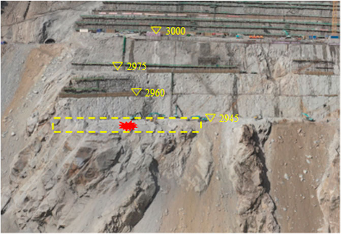
Figure 7. Blasting test area.
A total of 114 main holes were arranged in five rows in test. The hole spacing was 2.5∼3.5 m, and hole array pitch was 2.3–3.2 m. In order to compare the blasting differences of different coupling media, the blasting area is divided into two parts. The upstream side of blasting area is conventional air-coupled blasting, and the downstream side of blasting area is water-coupled blasting. The plane layout of borehole is shown in Figure 8.
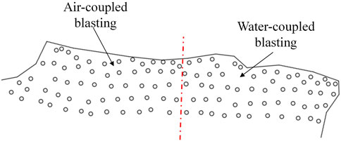
Figure 8. Layout of borehole.
The diameter of main borehole is 115 mm, and the diameter of cartridge is 70 mm or 32 mm. The charge is mainly 70 mm diameter cartridge, and the single hole charge is distributed in 84∼96 kg. The specific blasting parameters are shown in Table 3. In water-coupled blasting area, water is injected into borehole after charging, and secondary water injection is carried out after plugging to ensure the water-coupled environment.
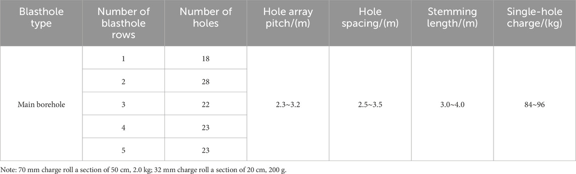
Table 3. Table of blasting parameters.
The borehole adopts continuous charge, and two detonators are arranged in the middle and top of charge section respectively. The detonating network adopts the detonating tube detonator network, and the double-detonating MS13 detonator is set in main borehole, and the MS3 detonator is used to transmit the explosion between segments and the MS5 detonator is used to transmit the explosion between rows.
5.2 Test results
Using UAV to collect blasting block image from the upstream side, downstream side, front and top of blasting pile. The artificial high-definition camera is used to collect blasting block image of blasting pile area near the reserved rock. The typical blasting block image collected is shown in Figure 9.
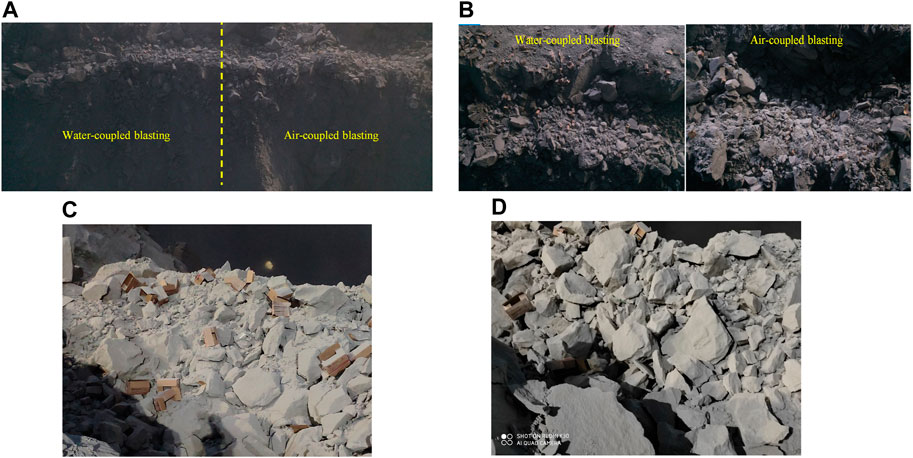
Figure 9. Typical blasting block image. (A) Front of blasting pile. (B) Top of blasting pile. (C) Upstream side of blasting pile. (D) Downstream side of blasting pile.
In order to quantitatively analyze and process the image, the long sides of explosive pack boxes left in different positions of blasting pile are used as the scale, as shown in Figure 10. The actual size of long sides is 50 cm.
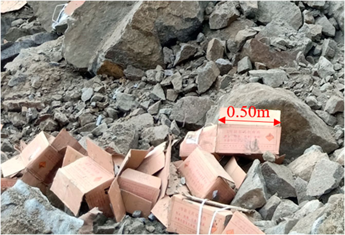
Figure 10. Scale for blasting block analysis.
The upstream side of blasting test is air-coupled blasting area, and the downstream side is water-coupled blasting area. Then, the block analysis of two test areas is carried out respectively. The blasting block image taken when the lens was parallel to blasting pile was selected and guided into WipFrag software, the image scale was set, and the software was used to automatically identify the blocking edge and manually correct the wrong edge. Based on the manually corrected results, WipFrag software automatically generates a single blasting block distribution curve, and finally combines multiple blasting block distribution curves to obtain the lumpiness distribution curves of two blasting areas in test, as shown in Figure 11.
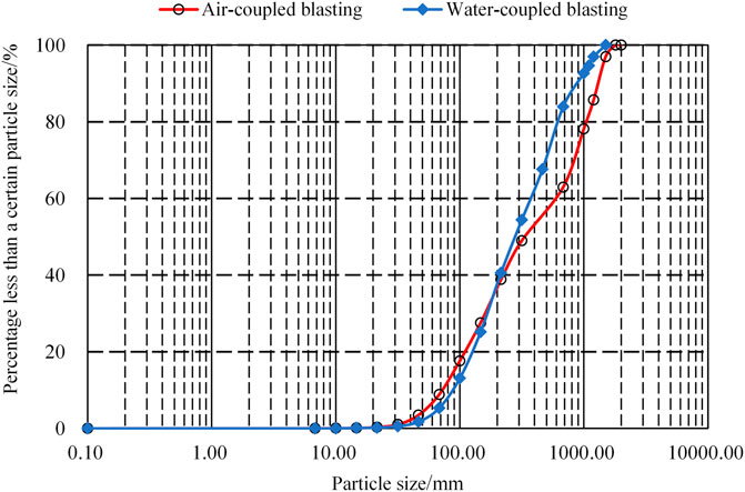
Figure 11. Blasting test block distribution curve.
The most intuitive evaluation index of blasting block distribution curve is the mean diameter x50 and the non-uniformity coefficient Cu of graded material. Cu < 5 indicates uniform particle size distribution, and the larger non-uniform coefficient, the more uneven particle size distribution. The calculation formula of non-uniformity coefficient Cu is as follows:
Where x60 and x10 represent rock sizes with 60% and 10% cumulative rates under minus mesh material, respectively.
The main parameters of blasting block in different test areas obtained by WipFrag are shown in Table 4. From Eq. 13 the mean diameter of rock blocks in air-coupled blasting is 342.36 mm, and the non-uniformity coefficient is 8.10. The mean diameter of rock blocks in water-coupled blasting area is 283.74 mm, and the non-uniformity coefficient is 4.29. The mean diameter in water-coupled blasting area is smaller than that in conventional blasting area. The particle size distribution is more uniform, which is conducive to improving the rock fragmentation efficiency.
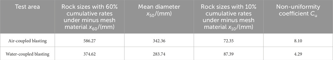
Table 4. Table of fragmentation size distribution parameters of rock after blasting.
6 Conclusion
The main conclusions are as follows:
(1) Based on stress wave theory and variation law of strain rate near borehole area, a distribution model of blasting fragmentation is established considering the effect of rock mass strain rate. When blasting medium is determined, the blasting fragmentation size is negatively correlated with the borehole pressure and unit explosive consumption.
(2) In water-coupled blasting, the existence of water makes the blasting pressure transmitted to hole wall significantly greater than that of air-coupled one, and prolongs the duration of blasting load, improves the work of explosive on rock, and is equivalent to improving the unit explosive consumption. Compared with air-coupled blasting, water-coupled blasting can improve rock fragmentation, and the rock fragmentation size is smaller.
(3) The pseudo three-dimensional numerical simulation of bench blasting with different coupling media was carried out. The rock rupture development speed of water-coupled blasting is obviously better than that of air-coupled one, and the development degree of final cracks is far higher, that is, water-coupled blasting has a stronger crushing effect on rock, which is conducive to reducing the generation of large blocks after blasting.
(4) Field tests of bench blasting with different coupling media were carried out, and the lumpiness distribution curves of rock mass after blasting were obtained. The test results show that the mean diameter of rock in water-coupled blasting area is smaller and the particle size distribution is more uniform.
Data availability statement
The original contributions presented in the study are included in the article/Supplementary Material, further inquiries can be directed to the corresponding author.
Author contributions
TL: Writing–original draft, Writing–review and editing. MC: Resources, Supervision, Validation, Writing–review and editing. B-wG: Writing–review and editing. LS: Writing–review and editing. BF: Writing–review and editing. S-sC: Writing–review and editing.
Funding
The authors declare that financial support was received for the research, authorship, and/or publication of this article. This work is supported by Chinese National Natural Science Foundation (No. 52309156), the Science and technology development fund project of the Yellow River Water Conservancy Research Institute (202306), the Special Items of Basic Business Expenses of Central Public Welfare Scientific Research Institutes (HKY-JBYW-2023-04) and the Science and technology project for outstanding young talents of the Yellow River Commission (HOK-202314).
Acknowledgments
The authors wish to express they’re thanks to the supporter.
Conflict of interest
The authors declare that the research was conducted in the absence of any commercial or financial relationships that could be construed as a potential conflict of interest.
Publisher’s note
All claims expressed in this article are solely those of the authors and do not necessarily represent those of their affiliated organizations, or those of the publisher, the editors and the reviewers. Any product that may be evaluated in this article, or claim that may be made by its manufacturer, is not guaranteed or endorsed by the publisher.
Supplementary material
The Supplementary Material for this article can be found online at: https://www.frontiersin.org/articles/10.3389/feart.2024.1445990/full#supplementary-material
References
Chen, M., Ye, Z. W., Lu, W. B., Wei, D., and Yan, P. (2020). An improved method for calculating the peak explosion pressure on the borehole wall in decoupling charge blasting. Int. J. Impact Eng. 146, 103695. doi:10.1016/j.ijimpeng.2020.103695
Chi, L., Zhang, Z., Aalberg, A., and Li, C. (2019). Experimental investigation of blast-induced fractures in rock cylinders. Rock Mech. Rock Eng. 52, 2569–2584. doi:10.1007/s00603-019-01749-0
Cho, S. H., and Kaneko, K. (2004). Influence of the applied pressure waveform on the dynamic fracture processes in rock. Int. J. Rock Mech. Min. Sci. 41 (5), 771–784. doi:10.1016/j.ijrmms.2004.02.006
Dai, J., and Qian, Q. (2008). Control of size of rock fragmentation by blasting. J. Liaoning Tech. Univ. Nat. Sci. Educ. 27 (1), 54–56. doi:10.3969/j.issn.1008-0562.2008.01.016
Dong, Y., Xia, C., and Duan, Z. (2006). Numerical analysis of plane explosive wave propagation with its attenuation behavior in semi-infinite medium. Eng. Mech. 23 (2), 60–65. doi:10.3969/j.issn.1000-4750.2006.02.011
Grady, D. (1982). Local inertial effects in dynamic fragmentation. J. Appl. Phys. 53 (1), 322–325. doi:10.1063/1.329934
Huang, P., Wu, E. H., and Liu, Q. S. (2014) “The controlled blasting technology of sewage treatment pool concrete wall water hole in complicated environment,” in Manufacturing and Engineering Technology. Boca Raton, FL: CRC Press.
Jang, H., Handel, D., Ko, Y., Yang, H., and Miedecke, J. (2018). Effects of water deck on rock blasting performance. Int. J. Rock Mech. Min. Sci. 112, 77–83. doi:10.1016/j.ijrmms.2018.09.006
Jiang, F., Li, X., Li, G., and Sheng, Y. (2015). Modification on calculation formula of rock mass blastability index based on rough set and nonlinear multiple regession. J. Saf. Sci. Technol. 11 (1), 34–39. doi:10.11731/j.issn.1673-193x.2015.01.006
Katsabanis, P. D. (2020). Analysis of the effects of blasting on comminution using experimental results and numerical modelling. Rock Mech. Rock Eng. 53, 3093–3109. doi:10.1007/s00603-020-02093-4
Li, Q. (2009). Experiment of fracture behaviors and control for crack propagation under blasting load. Beijing: China University of Mining & Technology.
Li, T., Chen, M., Ye, Z., Lu, W., and Wei, D. (2021). Study on the energy transfer efficiency of explosive blasting with different coupling medium. Explos. Shock Waves 41 (06), 4–14. doi:10.11883/bzycj-2020-0381
Liu, L., and Katsabanis, P. D. (1996). Numerical modeling of the effects of air-decking/decoupling in production and controlled blasting. Rock Fragm. by Blasting, Rotterdam, 319–330.
Mead, D., Moxon, N., and Danell, R. (1993). The use of air-decks in production blasting, in Proceedings of the Fourth International Symposium on Rock Fragmentation by Blasting, Vienna, Austria, July 5–8, 437–443.
Melnikov, N. V. (1962). Influence of explosive charge design on results of blasting. Min. Res., 147–155. doi:10.1016/b978-1-4832-8307-4.50017-9
Moxon, N., Mead, D., and Richardson, S. (1993). Air-decked blasting techniques: some collaborative experiments. Int. J. Rock Mech. Min. Sci. &Geomechanics Abstr. 30 (5), 303. doi:10.1016/0148-9062(93)92504-j
Park, D., and Jeon, S. (2010). Reduction of blast-induced vibration in the direction of tunneling using an air-deck at the bottom of a blasthole. Int. J. Rock Mech. Min. Sci. 47 (5), 752–761. doi:10.1016/j.ijrmms.2010.04.011
Sher, E. N., and Aleksandrova, N. I. (2007). Effect of borehole charge structure on the parameters of a failure zone in rocks under blasting. J. Min. Sci. 43 (4), 409–417. doi:10.1007/s10913-007-0040-4
Shi, C., Zhao, Y., Zhao, C., Lou, Y., Sun, X., and Zheng, X. (2022). Water-Sealed Blasting Control Measures of the metro Station undercrossing Existing Structures in Ultra-close Distances: A Case Study. Front. Earth Sci. 10, 848913. doi:10.3389/feart.2022.848913
Wang, J., Yang, J., Wu, F., and Afaisal, S. (2020). Analysis of fracture mechanism for surrounding rock hole based on water-filled blasting. Int. J. Coal Sci. Technol. 7 (4), 704–713. doi:10.1007/s40789-020-00327-y
Wang, W., Li, X., Shi, L., and Fang, Z. (2008). Discussion on decoupled charge loosening blasting in deep rock mass. Rock Soil Mech. 29 (10), 2837–2842. doi:10.1016/S1872-5813(08)60033-X
Wang, Z., and Li, Y. (2005). Numerical simulation on effects of radial water-decoupling coefficient in engineering blast. Rock Soil Mech. 26 (12), 1926–1930. doi:10.1360/biodiv.050084
Wei, D., Chen, M., Ye, Z., Lu, W., and Li, T. (2021). Study on Blasting Failure Zone Based on Rate-dependent Dynamie Characteristics of Rock Mass. Adv. Eng. Sci. 53 (01), 67–74. doi:10.15961/j.jsuese.201900872
Xie, X., Li, J., and Zheng, Y. (2023). Experimental study on dynamic mechanical and failure behavior of a jointed rock mass. Int. J. Rock Mech. Min. Sci. 168, 105415. doi:10.1016/j.ijrmms.2023.105415
Yan, G., and Yu, Y. (2009). Numerical simulation of air and water medium decoupling charge blasting. Eng. Blasting 15 (4), 13–19.
Yang, R., Ding, C., Yang, L., Lei, Z., and Zheng, C. (2019). Study of decoupled charge blasting based on high-speed digital image correlation method. Tunn. Undergr. Space Tech. 83, 51–59. doi:10.1016/j.tust.2018.09.031
Ye, Q., Jia, Z. Z., and Zheng, C. S. (2017). Study on hydraulic-controlled blasting technology for pressure relief and permeability improvement in a deep hole. J. Petroleum Sci. Eng. 159, 433–442. doi:10.1016/j.petrol.2017.09.045
Ye, Z. W., Chen, M., Li, T., et al. (2021). A simplified calculation method of the peak pressure on borehole wall for water-coupling contour blasting. Rock Soil Mech. 42 (10), 2808–2818. doi:10.16285/j.rsm.2021.0094
Yin, Z., Wang, D., Wang, X., Dang, Z., and Li, W. (2021). Optimization and Application of Spacing Parameter for Loosening Blasting with 24-m-High Bench in Barun Open-Pit Mine. Shock Vib. 2021, 1–13. doi:10.1155/2021/6670276
Yu, L., Zhou, L., Hu, Y., and Hu, W. (2021). Experimental study on delay optimization between blasting holes in grade batching mining of lianghekou hydropower station. Blasting 38 (4), 81–88.
Zhang, Q. (1990). Smash districts and expanding of cavities in rock blasting. Explos. Shock Waves 1990 (01), 68–75.
Keywords: rock blasting, decoupling charge, coupling medium, fragmentation size, borehole pressure, unit explosive consumption
Citation: Li T, Chen M, Guo B-w, Song L, Fan B and Cui S-s (2024) Study on fragmentation characteristics of rock mass in bench blasting with different coupling media. Front. Earth Sci. 12:1445990. doi: 10.3389/feart.2024.1445990
Received: 08 June 2024; Accepted: 12 July 2024;
Published: 02 August 2024.
Edited by:
Faming Huang, Nanchang University, ChinaReviewed by:
Yusong Miao, Qingdao University of Technology, ChinaChengyu Xie, Xiangtan University, China
Copyright © 2024 Li, Chen, Guo, Song, Fan and Cui. This is an open-access article distributed under the terms of the Creative Commons Attribution License (CC BY). The use, distribution or reproduction in other forums is permitted, provided the original author(s) and the copyright owner(s) are credited and that the original publication in this journal is cited, in accordance with accepted academic practice. No use, distribution or reproduction is permitted which does not comply with these terms.
*Correspondence: Li Song, aGt5c2wxOTc4QDEyNi5jb20=