 Changfu Huang1,2
 Shaohua Li
- 1China Railway 15th Bureau Group Co., Ltd., Shanghai, China
- 2China Railway 15th Bureau Group No. 5 Engineering Co., Ltd., Tianjin, China
- 3China Railway First Survey and Design Institute Group Co., Ltd., Xi’an, China
Tunnel construction subject to surrounding rock squeezing deformation can induce support cracking, intrusion, and collapse. Herein, the existing Wushaoling tunnel of Lanzhou–Wuwei second line railway and the new Wushaoling tunnel of Lanzhou–Zhangye third and fourth line railways are compared to analyze and discuss the progress in deformation control techniques for railway tunnels surrounded by squeezing rock. Further, a technical system for large deformation control is preliminarily established. The maximum support deformation of the Wushaoling tunnel do not exceed the reserved deformation. The large deformation of tunnel surrounding rock is generally controlled to achieve better support effect. The main control measures are as follows. (1) The section design method based on the deformation classification is suitable for squeezing surrounding rock. (2) The support structure design involves anti-releasing and early controlled releasing, and measures such as increased support stiffness, increased reserved deformation, and multi-layer supports can be employed. (3) The micro-bench method reduces the closure time of the inverted arch to control deformation. (4) To realize quick excavation and support and reduce the disturbance to the surrounding rock, a cantilever excavating machine can be used for excavation and an intelligent arch trolley can be utilized to realize unmanned vertical arch drilling, anchoring, and grouting.
1 Introduction
During tunnel construction, the large deformation of the surrounding rock that squeezes the tunnel is one of the main problems faced by tunnel builders. This squeezing surrounding rock is a type of rock mass that undergoes significant plastic deformation in a certain range around a tunnel in a high geo-stress environment. This type of rock generally has low strength, poor integrity, high geo-stress, and a high strength–stress ratio and undergoes strong deformation. Tunnel excavation often leads to deformation growth, aggravation, and long-term deformation of the surrounding rock. It also causes the deformation of the initial support to exceed the limit, inducing cracking, blocking, steel frame distortion, and even local collapse or secondary lining cracking, which seriously affects the construction safety and progress.
Tunnel engineers commonly encounter large deformations caused by squeezing surrounding rock, which lead to construction problems, such as those occurring at Taoen Tunnel, Turin Tunnel, Alberg Tunnel, Wushaoling Tunnel of Lanwu Second Line, Muzhailing Tunnel of Lanyu Railway, Xinchengzi Tunnel of Lanyu Railway, and Yuelongmen Tunnel of Chenglan Railway. With the construction experiential knowledge gained through the above projects, many achievements have been made in research on tunnels with squeezing surrounding rock in recent years.
Regarding the classification of the rock surrounding and squeezing tunnels, Liu et al. (2008) utilized the field measurement data of the Wushaoling Tunnel of Lanwu second line, combined with theoretical calculations and previous experience with similar tunnels; took the relative deformation of the surrounding rock, strength–stress ratio, original ground stress, and elastic modulus as classification indices; and employed the large deformation classification standard given by the comprehensive index determination method. Li et al. (2015) classified the large deformation of the Lanzhou–Chongqing Railway tunnel with squeezing surrounding rock and studied the large deformation mechanism and law of the tunnel. In the design stage, the authors used the relative deformation and rock strength–stress ratio Rc/p0 for prediction and divided the deformation grades into three levels. In the construction stage, the deformation (u) and deformation rate (v) were used to verify the evaluation and deformation management. Based on the large deformation classification method of Hoek and a large number of stress tests of supporting structures in Chenglan Railway, Guo (2019) divided the deformation of the Chenglan Railway tunnel with squeezing surrounding rock into four grades by using a supporting resistance-to-ground stress ratio of 0.04. Based on the Muzhailing Tunnel Project of Lanzhou–Chongqing Railway, Wang R. et al. (2020) established a displacement management benchmark for carbonaceous slate tunnel supports and a classification standard for large squeezing deformation based on field monitoring measurement data and on-site construction process investigation results. They considered the perspectives of facilitating stress release, controlling support deformation, and reducing the pressure of secondary lining squeezing deformation. In recent years, Chinese scholars have divided the large tunnel deformation caused by squeezing soft rock into four grades: grade I (slight), grade II (medium), grade III (strong), and grade IV (extremely strong) according to the deformation potential. The deformation grade is determined according to factors such as the deformation potential, rock mass strength–stress ratio, and relative deformation (China Railway Corporation, 2019; Liu and Li, 2020). Arora et al. (2023) classified compressive surrounding rock by using the classification system of tunnel radial strain through similar simulation experiments. By analyzing the convergence of the tunnel at different times and under different stress levels, a longitudinal displacement profile model of the tunnel with time was proposed.
Regarding the supporting structure design, Li et al. (2022) combined the construction experiential knowledge obtained through typical railway tunnels with squeezing surrounding rock, such as the Lanzhou–Chongqing, Lanzhou–Xinjiang, and Chengdu–Lanzhou Railway Tunnels in China. They focused on addressing the problems of inaccurate determination of the deformation potential of the squeezing surrounding rock, unclear design load, and unreasonable pre-designed supporting systems and discussed the deformation mechanism and characteristics of the squeezing surrounding rock. Based on the deformation potential and classification standard of the squeezing surrounding rock, a new tunnel design method and deformation control technology were proposed (Yang et al., 2023). To optimize the cross-section shape of a tunnel in squeezing surrounding rock, the cross-section shapes of single- and double-line railway tunnels were derived based on the construction limits of 200 km/h passenger–freight railway tunnels. Through structural safety evaluations, more economical and safe cross-section forms of single- and double-line railway tunnels under different deformation grades were proposed (Wang Y. et al., 2020). Taking the Shenbei New Area Tunnel of the Lanzhou–Chongqing Railway as an example, the initial support displacement and stress of the lining structure under four flat ratios were studied by numerical simulation, leading to the conclusion that the maximum flatness of the cross-section could be adjusted to less than 0.8. He et al. (2021) invented an adaptive steel arch joint suitable for large deformation tunnels in soft rock based on the yield support concept of energy release. The joint realizes yield pressure by sliding, which can significantly reduce the surrounding rock pressure and maximize the performanceof the supporting materials.
To solve the problems of rod fracture and plate yielding of full-length bonded long bolts in the supports of tunnels that undergo large squeezing deformation, Guo et al. (2023) proposed a self-advancing yielding (combined) bolt. By forming an unbonded section on the part of the bolt body with a smooth sleeve, the unbonded section yielded before the bolt system failed, which realized the yielding of the long bolt under the condition of full-length grouting and improved the overall stability of the bolt system. Majumder et al. (2022) utilized the Maneri–Bhali phase I hydropower project (India) as an engineering example to develop a model of a tunnel with squeezing surrounding rock in different construction stages. According to the tunnel convergence, stress component, surrounding rock characteristic curve, and support characteristic curve, the interaction response of the tunnel–support structure was quantified. Wang et al. (2019) took four tunnels in the squeezing mountainous area of Qingling Dam as examples. Focusing on the problems of extreme rock mass deformation, structural cracks, and damage during excavation, a strong support system suitable for tunnels surrounded by squeezing rock was established. The system included key technologies such as supporting bolts, overall strong support measures, and more reserved deformations. Guan et al. (2020) established a theoretical model based on the finite strain method to describe the multiple disturbances of a tunnel face in compressive surrounding rock. The influences of the post-peak behavior of the surrounding rock, surrounding rock conditions, and old temporary supports on the disturbance of the tunnel face were clarified. Xu et al. (2023) took the Qinghe Tunnel of Zhaolu Expressway in Yunnan Province as an example to analyze the application of compressible supports in squeezing surrounding rock. When two symmetrical longitudinal compressible elements were installed in the lining, the support pressure required for balance was greatly reduced, and the support pressure distribution at the contact of rock support was more uniform. Liu et al. (2021) took the Lianchengshan Tunnel as an engineering example and studied the deformation behavior and mechanical mechanisms of primary and secondary lining methods in the squeezing surrounding rock. The double-layer primary lining method was found to be more effective than the single-layer primary lining method in restraining the deformation of the surrounding rock, and the maximum vertical displacement and horizontal convergence were reduced by 67% and 66%, respectively.
In the construction control measures of squeezing surrounding rock tunnel, Li et al. (2019) considered the previous experience of squeezing large deformation tunnel construction and divided the deformation of tunnels with squeezing surrounding rock into three types, namely, stress, structural, and composite, based on the stress field distribution characteristics. According to the total amount of deformation, the deformation potential was classified as conventional, slight, medium, or strong. The deformation potential increased with increasing deformation rate, according to the initial deformation rate of the support, and the strength of the deformation potential and adaptability of the surrounding rock and support system were evaluated. The action mechanisms of long, medium, and short bolts in a tunnel with squeezing surrounding rock were revealed; the construction time of a bolt system was analyzed; and reasonable forms of steel frame and reserved deformation were determined. The construction time of the secondary lining of squeezing surrounding rock was proposed to be controlled to 2–4 mm/d. Ma et al. (2021) summarized the construction practice experience of nearly 10 high geo-stress soft rock tunnels along the Lixiang, Yumo, and Chenglan Railways and expounded the deformation characteristics and key control technologies of large deformation tunnels. Their key findings were as follows: the reserved deformation is an important basis for avoiding the invasion of primary supports after large deformation; for a single-line tunnel with dominant horizontal tectonic stress, increasing the curvature of the side wall can effectively control the convergence of the tunnel side wall; and the combined support of a double-layer primary support and bolt can effectively improve the stiffness of the primary support and reduce the deformation of the surrounding rock. The primary support inverted arch is quickly closed, and the distance between the primary support inverted arch and the working face is controlled to be less than 20 m, which can effectively inhibit the convergence. Appropriate timing of secondary lining construction can effectively control large deformation and reduce the cracking of the secondary lining. Sun (2012) and Li and Li (2018) performed numerous field tests and verifications in the engineering of tunnels with squeezing surrounding rock. The engineering geological characteristics, geo-stress characteristics, deformation characteristics, support pressure, stress characteristics, and support failure characteristics of soft rock tunnels were systematically analyzed. On this basis, a deformation control system considering different deformation levels was proposed. This system increased the reserved deformation and utilized long bolts, double-layer supports, reserved reinforcement spaces, reinforcement radial grouting bolts, short benching, early closure, temporary inverted arches, and other measures. Tian et al. (2021) and Zhou et al. (2024) considered the deformation mechanism of tunnels with squeezing surrounding rock and the principle of active support. They used the concept of active control to improve the stress state, reduce the disturbance, and provide active reinforcement to the surrounding rock. Simultaneously, the authors fully utilized the self-bearing capacity of the surrounding rock and proposed advance supports, prestressed bolts (cables), and shotcrete as the main support means. Thus, they actively improved the mechanical parameters of the surrounding rock or reduced the damage caused by construction to the mechanical parameters of the surrounding rock and implemented active, timely, and effective support forces. The design concept of active support for tunnel deformation control fully mobilizes the self-stability of the surrounding rock. Kang et al. (2021) proposed a new support method of “surrounding rock support + rock modification + pressure relief” for coal mine roadways with squeezing surrounding rock. Ramoni and Anagnostou (2010) studied the thrust of the tunnel boring machine (TBM) method in the construction of tunnels in squeezing surrounding rock and calculated the relevant parameters by performing a finite element simulation. According to the calculation results, reducing the shield length, installing higher thrust, and increasing the over-excavation or lubrication of the shield surface can effectively improve the construction efficiency. Dwivedi et al. (2013) developed a method of predicting tunnel deformation based on regression analysis according to the surrounding rock deformation data of 75 squeezing tunnels in the Himalayan region. This method takes the rock mass quality index, number of rock masses, ratio of horizontal stress to vertical stress, joint coefficient, bearing stiffness, vertical stress, and tunnel radius as control parameters to establish a correlation.
Systematic research on the deformation control technology of tunnels with squeezing surrounding rock in China began with the Wushaoling Tunnel of Lanzhou–Wuhan Second Line (started in 2003), which is one of the landmark projects of railway development in China. The tunnel is a typical high ground stress weak surrounding rock. Deformation control is extremely difficult, and the construction risk is extremely high. Through scientific research, design, construction, and other experiences, various technical problems were finally overcome to ensure the successful construction of the project. However, in the early stage of construction, due to the lack of understanding of squeezing surrounding rock and related experience, the maximum squeezing deformation rate of the surrounding rock exceeded 167 mm/d. The total deformation was up to 120 cm. Some sections even exhibited a secondary lining crushing phenomenon, many times due to deformation or collapse shutdown. The new Wushaoling Tunnel of Lanzhou–Zhangjiakou Third and Fourth Lines was started in 2018. Based on the construction experience of the existing Wushaoling tunnel and other squeezing surrounding rock tunnels, the smooth progress of the project is ensured by adopting reasonable structural design and construction control measures, and the maximum deformation is much smaller than that of the existing Wushaoling tunnel.
This study combines the existing and new Wushaoling tunnel engineering practice to provide an analysis of the design and construction methods of tunnels with squeezing surrounding rock. Approaches for reforming the design methods and deformation control technology of these tunnels are expounded.
2 Overview of the Wushaoling Tunnel project
2.1 Regional geological conditions
The Wushaoling Tunnel is located in the northeastern margin of the Qinghai–Tibet Plateau at an altitude of 2,900–3,600 m and belongs to the Qilian fold system in the tectonic unit. The lithology of the cross-mountain area is complex. Sedimentary, magmatic, and metamorphic rocks are distributed, with sedimentary rocks being the main rock type. The distribution is mainly controlled by regional fault structures. The fault structure is developed in the tunnel site area and is mainly a regional large fault. In a range of nearly 8 km in the ridge section, a wide compressional tectonic belt exists that is composed of four regional large faults (F4–F7) as the skeleton. The secondary faults in the belt are developed due to tectonic action. The cut Paleozoic, Mesozoic, and Caledonian rock masses are overturned on the Pliocene strata, and the geo-stress conditions are extremely complicated. Among them, F7 is a Holocene active fault with a width of 820 m. In the range of faults, especially in the F4 and F7 fault zones and Silurian slate with phyllite sections, the surrounding rock is incredibly broken, the geo-stress level is high, the squeezing effect of the surrounding rock is significant, and the self-stabilization ability of caverns is exceedingly poor.
2.2 Existing Wushaoling Tunnel
The existing Wushaoling Tunnel, built in 2003–2006, is a typical case of a tunnel with large deformation in soft rock and is the longest single-track railway tunnel in China. It is a double-hole, single-line tunnel. The line spacing is 40 m, left and right line tunnel lengths are 20,050 m, design speed is 160 km/h, tunnel elevation is above 2,400 m, design elevation of the tunnel entrance rail surface is 2,662.84 m, design elevation of the exit rail surface is 2,446.80 m, and maximum buried depth of the tunnel is 1,100 m.
The tunnel adopts the route scheme of crossing major faults at a large angle. The cave passes through six sets of soft and hard interactive sedimentary and metamorphic rocks in the Quaternary, Tertiary, Cretaceous, Triassic, Silurian, and Ordovician. Eighteen faults exist in total. The tunnel crosses the regional compressional tectonic belt composed of F4, F5, F6, and F7 regional faults and three hydrogeological zones of medium water-rich, weak water-rich, and water-poor. The measured strength stress ratio Rc/σH of the surrounding rock is 1.2–11.3, in which the strength–stress ratio of the surrounding Silurian phyllite and F7 fracture zone is 0.031–0.063, and the tunnel is in a state of high and extremely high geo-stress. Several problems exist, including complex high geo-stress and deformation of weak surrounding rock in a wide range of tunnel sites, and the geological conditions have a rare level of complexity. The longitudinal section of the tunnel is shown in Figure 1.
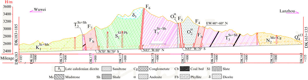
Figure 1. Longitudinal section of the existing Wushaoling Tunnel.
2.3 New Wushaoling Tunnel
The new Wushaoling Tunnel is 17,125 m long. It is a double-line, single-hole tunnel with a design speed of 250 km/h. Construction began in 2018. This tunnel is located on the east side of the existing Wushaoling Tunnel. The distance from the existing right-line tunnel is approximately 213 m (Zhangye end)–576 m (Lanzhou end), and the rail surface elevation is approximately 36 m (Zhangye end)–110 m (Lanzhou end) higher than that of the existing tunnel. The maximum buried depth of the tunnel is 952 m. The new Wushaoling Tunnel is almost parallel to the existing Wushaoling Tunnel, and the geological conditions are basically the same. The design and construction refer to the construction site of the existing Wushaoling Tunnel. The plane position relationship between the existing and new Wushaoling tunnels is shown in Figure 2.
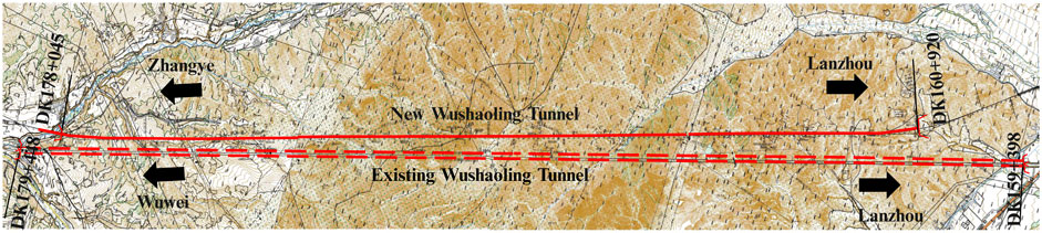
Figure 2. Plane position relationship between the existing and new Wushaoling tunnels.
3 Design and construction of the Wushaoling Tunnel of the Lanwu Second Line
3.1 Tunnel design
The existing Wushaoling Tunnel is made up of two single-line tunnels with cross-sectional areas of approximately 56–100 m2. The tunnel structure in the general section is elliptical with a curved wall and inverted arch lining, and the circular section is adopted in the F7 fault section. Figure 3 depicts the section form and support parameters of the ridge phyllite section, which was constructed by the two-step method.
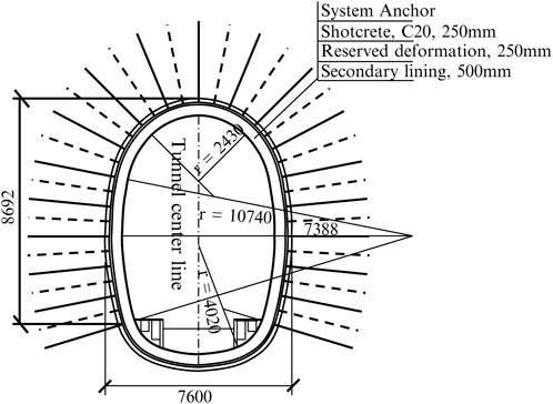
Figure 3. Lining structure of the existing Wushaoling Tunnel in the phyllite cross ridge section.
Figure 4 shows the circular composite lining structure of the F7 fault section. In the 150° range of the arch, the advance pipe roof pre-grouting with a length of 10 m and a diameter of 80 mm is adopted to reinforce the stratum and play a supporting role. The I-16 steel frame is constructed via the step method, and the temporary inverted arch is set at the bottom of the upper step.
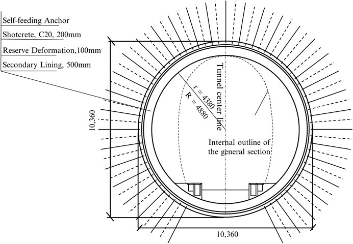
Figure 4. Lining structure of the existing Wushaoling Tunnel in the F7 fault zone section.
3.2 Tunnel deformation
When the tunnel construction entered the ridge F4–F7 squeezing structure zone, different degrees of deformation occurred. Some of the initial support intruded into the secondary lining limit; some of the shotcrete was damaged, cracked, and squeezed; and the steel frame was distorted and even collapsed. Among these problems, the deformation of F7 and the ridge squeezing structure in the Silurian phyllite section is the most serious. The deformation is large, deformation rate is rapid, and deformation control is extremely difficult.
3.2.1 Main belt of F7
After the construction entered the main zone of F7, the deformation rate began to increase. On 5 April 2004, the deformation rate of the initial support was found to exhibit an increasing trend and the initial support exhibited phenomena of falling blocks, cracking, and extrusion failure. Collapse occurred in the DK177 + 571–DK177 + 581 section of the left line tunnel at F7, and large deformation occurred in the DK177 + 409–DK177 + 571 section at 162 m. The deformation rate accelerated, and the deformation increased when the lower half section and invert of the right tunnel were excavated in late March 2004. The YDK177 + 440–YDK177 + 690 section invaded the secondary lining range to varying degrees.
The maximum vault subsidence and horizontal convergence of the tunnel are 1,209 and 1,053 mm, respectively, and generally can reach 300–700 mm. The initial deformation rate is typically 30–35 mm/d. Although measures such as fan-shaped supports and temporary arch suppression are employed, the deformation cannot be effectively controlled. Figure 5 shows the deformation of the main belt support of F7.
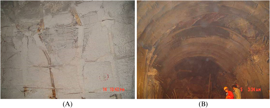
Figure 5. Deformation and failure of primary lining in F7 fault zone section of the existing Wushaoling Tunnel: (A) steel frame twisted and deformed and (B) shotcrete peeling and chipping.
According to the deformation and geological conditions of F7, numerous section forms, section clearance, support forms, and support parameters are optimized. The experimental study was conducted by using single-layer and multiple supports with different cross-section forms (circular, elliptical, and horseshoe). After optimization, a circular double-layer support section was finally adopted for the main section of F7. A layered secondary support (25 + 20 cm) was adopted as the initial support, and an 80 cm reinforced concrete structure was employed as the secondary lining. Simultaneously, a circuitous guide pit was set to release the surrounding rock pressure in advance. Finally, the deformation of the tunnel was reduced to 150–350 mm, the maximum daily deformation was approximately 20 mm/d, and the deformation of the primary support was effectively controlled.
3.2.2 Silurian phyllite strata
The tunnel in the Silurian phyllite stratum is greatly affected by F7 and located in the middle of several large extrusion tectonic belts in the ridge. The buried depth is large, ground stress is high, and phyllite rock is weak. During the construction of the inclined shaft, many shutdowns occurred due to the internal movement of the support, and the maximum internal movement was approximately 1.2 m. After beginning the main tunnel construction, the tunnel deformation was large and the convergence deformation in the phyllite-based strata reached 500–700 mm. Figure 6 shows the deformation of the Silurian stratum support.
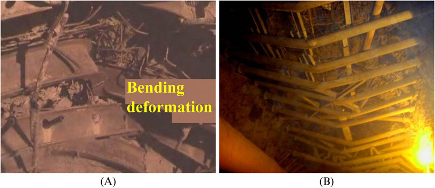
Figure 6. Deformation and failure of primary lining in Silurian strata of the existing Wushaoling Tunnel: (A) steel frame twisted and deformed and (B) temporary brace bent.
In the later stage of construction, according to the large, buried depth of the phyllite stratum in the ridge section, the rock was weak, and large deformation occurred during construction. Based on the original design of the combined support of the elliptical section anchor, shotcrete, and steel frame, measures such as changing the bolt to an anchor pipe, changing the I-steel frame to an H-steel frame, employing the ultra-short step method (three steps), utilizing flexible bolts instead of a temporary transverse support, and using 4–6-m-long system bolts were adopted, and the deformation control effect improved.
3.2.3 Deformation characteristics of the tunnel
1. The large deformation section is unusually long (Zhu et al., 2012). The tunnel passes through a wide active fault with a length of 820 m and a large deformation section of weak surrounding rock with a length of 7,587 m.
2. The deformation is large. The maximum horizontal convergence of the ridge section is 1,053 mm, and the maximum vault subsidence is 1,209 mm. The average accumulation is 90–120, 200–400, and 150–550 mm according to F4, Silurian phyllite, and F7, respectively, which is rare in tunnel engineering.
3. The initial deformation rate is fast. The maximum deformation rate of the ridge section is 167 mm/m, which is 73, 165, and 167 mm/d relative to the F4 fault zone, Silurian phyllite and F7 fault zone, respectively. The time point of the maximum deformation rate generally occurs before and after the excavation of the lower benching or inverted arch.
4. The deformation duration is long. The deformation duration of the large deformation section of the ridge section is generally more than 50 days and can be more than 150 days.
5. The relaxation range of surrounding rock induced by large deformation is considerable. The average accumulation calculated according to the F4 fault zone, Silurian phyllite, and F7 fault zone is 1.5–4.5, 1.4–3.1, and 2.2–7.9 m, respectively.
6. Various forms of support deformation and failure exist, and they are difficult to control. These mainly include vault sinking, sidewall squeezing, and floor heaving. After the support loses stability, collapse occurs immediately.
3.3 Existing problems
Because of the lack of understanding of the large deformation of soft rock in the early stage, corresponding design and construction measures are not in place, resulting in excessive deformation of the initial support, exceeding of the specified limitations, and even cracking of the secondary lining. Collapse or replacement occurred many times during the construction process.
1. The method of determining the surrounding rock pressure was not reasonable.
The load-structure method is widely used in tunnel structure design, and the surrounding rock pressure is the design basis. When calculating the pressure of the rock surrounding a deeply buried tunnel such as Wushaoling tunnel, the empirical formula of the loose pressure of surrounding rock obtained from landslide data is adopted obtained from the Code for design of railway tunnel (Tb10003-2001 Code for design of railway tunnel, 2016). The calculation method takes the grade of the surrounding rock as the main index. The preliminary design of the structure is completed, and it is implemented on site and dynamically adjusted according to the monitoring measurement results. When this method is applied to a tunnel with squeezing surrounding rock, due to the lack of resistance provided by the supporting structure, deformation intrusion, support replacement, collapse, and even secondary lining cracking and failure can occur. These incidents mainly occur because the deformation pressure is the main rock pressure on a tunnel with squeezing surrounding rock, and its value is much larger than that calculated by the statistical formula. Thus, the method of calculating the loose pressure based on the classification of the surrounding rock cannot be used for a tunnel with squeezing surrounding rock, which was not clearly recognized at the beginning of the design process.
2. The shape of the cavern selected at the beginning of the design is unreasonable.
In the early stage, the understanding of the mechanism of large deformation was insufficient, and the characteristics of the stress and deformation of the squeezing surrounding rock tunnel were not clear. At the beginning of the design, the elliptical section was selected, and the force was extremely unreasonable when the section shape was applied to the tunnel with squeezing surrounding rock.
3. The roles of the passive support and bolt are not prominent.
The system grouting bolt (pipe), together with the leading small pipe grouting, forms a unified surrounding rock reinforcement system, which can strengthen, reduce the cracking of, and improve the overall performance of the surrounding rock. Thus, it can control the deformation of the surrounding rock during the initial stage of tunnel excavation. The system grouting bolt (pipe), together with the leading small pipe grouting, forms a unified surrounding rock reinforcement system, which can strengthen the surrounding rock systematically, reduce the cracking of the surrounding rock, and improve the overall performance of the surrounding rock. Thus, it can control the deformation of the surrounding rock during the initial stage of tunnel excavation. In the design and construction process of the Wushaoling Tunnel, the role of the bolt was not fully recognized, resulting in an insufficient length of the pre-designed bolt; in particular, a long bolt was not set. In addition, the construction quality of the bolt due to time limitations is concerning.
4. The benching length is too long, and the support closure was not closed in time.
To utilize the working efficiency of the machinery fully to meet the requirements of the construction schedule, the benching length is often set too long. Consequently, the surrounding rock can easily collapse due to the excessive relaxation of the surrounding rock because of the late closure of the support. Taking the construction of the F7 fault zone as an example, before mid-April 2004, the benching length of the left tunnel was 61 m, and the distance between the tunnel face and the lining was 171 m. The benching length of the right tunnel was 34 m, and the distance between the tunnel face and the lining was 164 m. The main reasons for the increase in the deformation of the F7 tunnel were that the benching of the left and right tunnels were too long, the inverted arch was not closed in time, and the lining was seriously lagging behind.
5. The reserved deformation is insufficient.
The deformation prediction of the tunnel with squeezing surrounding rock is insufficient, resulting in the support deformation far exceeding the reserved deformation and causing the intrusion limit to be reached.
6. The thickness of the secondary lining is insufficient.
The thickness of the secondary lining is too small, resulting in insufficient rigidity and cracking of some secondary lining concrete.
4 Discussion
Because of the close distance between the new and existing Wushaoling tunnels, the geological conditions can be revealed by referring to the construction site of the existing Wushaoling Tunnel. However, due to the large cross-sectional area of the new Wushaoling tunnel, its deformation control is more difficult than that of the existing Wushaoling tunnel. Based on design, scientific research, and field tests and referring to the existing engineering experience, the large deformation control system of classification strengthening, tunnel optimization, support strengthening, moderate release, micro-benching excavation, and mechanized construction was adopted for the new Wushaoling Tunnel.
4.1 Deformation gradation
4.1.1 Deformation classification standard
When the geological conditions of high or extremely high geo-stress, that is, a saturated uniaxial compressive strength not more than 30 MPa and soft rock layer thickness of not more than 10 cm, are satisfied, the rock mass can be judged as compressible surrounding rock. According to the literature (China Railway Corporation, 2019; Liu and Li, 2020), the deformation grade of the compressive surrounding rock can be determined by the deformation potential, strength–stress ratio of the rock mass, and relative deformation. The deformation classification criterion standards are listed in Table 1. The construction stage can be adjusted according to the characteristics of the surrounding rock and the deformation characteristics of the tunnel face.
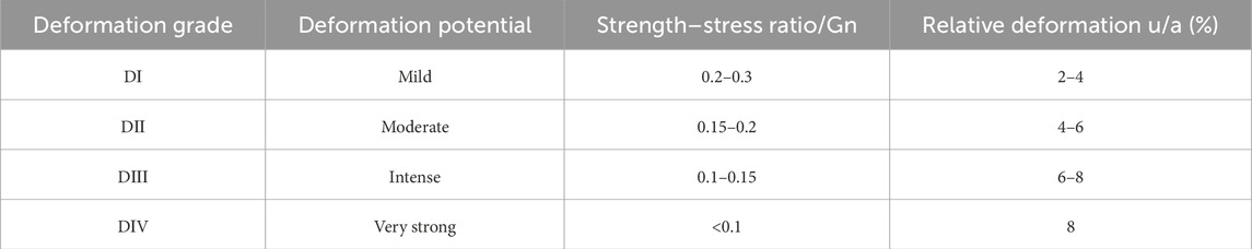
Table 1. Deformation grade division–Classification criteria of large deformation of ground squeezing tunnels.
4.1.2 Deformation grading results
During the construction of the existing Wushaoling Tunnel, the F4 and F7 fracture zones and Silurian phyllite and slate strata had different degrees of large deformation of the surrounding rock. Based on the survey and construction experiential knowledge of the existing Wushaoling Tunnel and Lanzhou–Chongqing Railway and the characteristics of the surrounding rock and geo-stress, large deformation may occur in the F4, F5, F6, and F7 fault zones of the new Wushaoling Tunnel with a total length of 1,555 m and in the Silurian strata with a length of 3,630 m. According to the deformation classification standard, the aforementioned deformation sections with a total length of 5,185 m can be divided into deformation grades. Among them, the section of grade I large deformation is 265 m long, accounting for 5.11%; that of grade II large deformation is 2,300 m long, accounting for 44.36%; that of grade III large deformation is 1815 m long, accounting for 35.0%; and that of grade IV large deformation is 805 m, accounting for 15.53%. The deformation classification results of the new Wushaoling Tunnel are summarized in Table 2 and Figure 7.
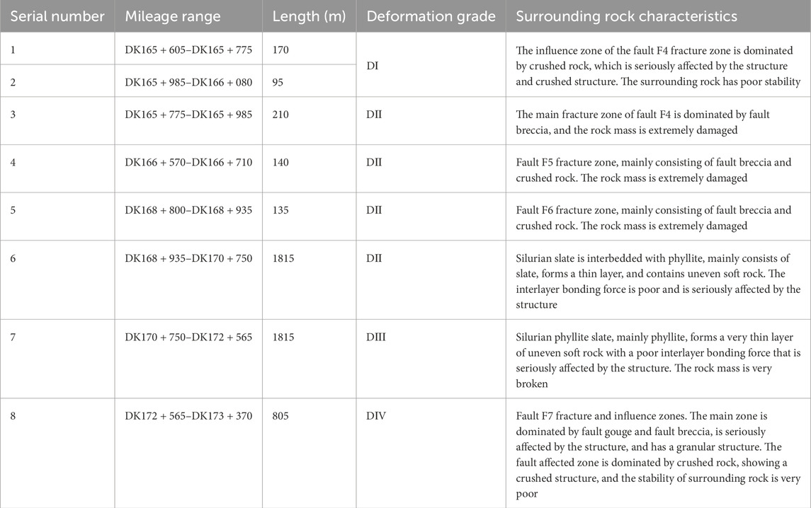
Table 2. Large deformation classification of rock surrounding the new Wushaoling Tunnel.
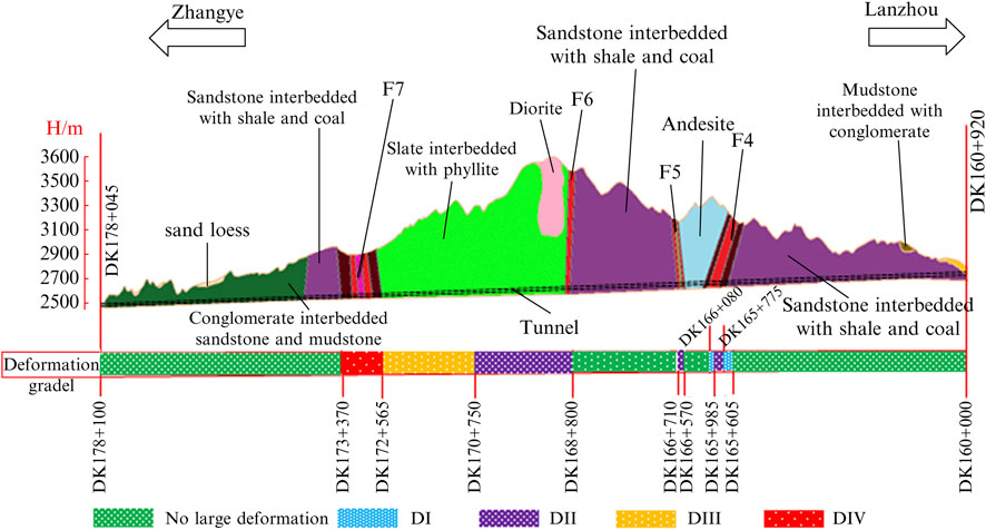
Figure 7. Deformation classification results of the new Wushaoling Tunnel.
4.2 Cross-section design based on deformation classification
4.2.1 Method for calculating the pressure of rock surrounding and squeezing a tunnel
The vertical uniform pressure (Equation 1) is dependent on the effects of the tunnel excavation span, buried depth, deformation grade of the squeezing surrounding rock, and natural constant. The lateral pressure coefficient is calculated according to the deformation grade when the horizontal uniform pressure is evaluated and can be obtained by applying the calculation method proposed by Liu and Li (2020).
Vertical uniform pressure:
where q is the vertical uniform pressure (MPa); b is the tunnel excavation span (m); h is the depth of the tunnel (m); S is 1, 2, 3, or 4, corresponding to deformation grades DI, DII, DIII, and DIV, respectively, of the surrounding compressive rock; and e is a natural constant.
The value standard of horizontal uniform load is shown in Table 3.

Table 3. Lateral pressure coefficient.
4.2.2 Tunnel shape
Flat or oval structural cross-sections are difficult to adapt to the extrusion environment. At present, the general practice worldwide is to use circular or near-circular cross-sections in severely deformed areas, such as the Sedrun section of the Swiss New St. Gotthard Tunnel with circular cross-sections and the F7 section of the Wushaoling Tunnel, ridge section of the Muzhailing Tunnel, and strong extrusion sections of the Japanese Huinashan Tunnel and Austrian Taoen and Alberg tunnels with near-circular cross-sections (Wang R. et al., 2020).
The load structure method was used to compare and analyze the stress and deformation characteristics of tunnel structures with different cross-section shapes under different deformation levels. The cross-section optimization of the new Wushaoling Tunnel was performed. Considering the reasonable space utilization rate, the four-center circular cross-section design was finally adopted. The lining section design of the large deformation section of the newly built Wushaoling Tunnel is shown in Figure 8, and the cross-sectional area of the tunnel is approximately 150–200 m2. Figure 8A depicts the lining section for a general section with grade V surrounding rock. In Figure 8B, sections VI and VII are suitable for a grade II large deformation section. In Figure 8C, section VIII is suitable for a grade III large deformation surrounding rock section. Finally, in Figure 8D, section VIV (double-layer support) is suitable for a grade IV large deformation section (F7 main belt). To adapt to the squeezing surrounding rock in a large deformation section more effectively, the curvature of the inverted arch can be further adjusted, the depth of the inverted arch can be deepened, and the rise-span ratio of the inverted arch can be increased. In this study, the grade I, II, and III large deformation sections were deepened by 60 cm; the inverted arch of the lining inner contour of the grade IV large deformation section was deepened by 110 cm; and the net width was widened by 50 cm (25 cm on each side) compared to the original design.
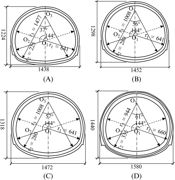
Figure 8. Section shape of lining in the large deformation section of new Wushaoling Tunnel (unit: cm): (A) general cross-section of Grade V surrounding rock; (B) cross-section of VDⅠ and VDⅡ; (C) cross-section of ⅤDⅢ; and (D) cross-section of VDⅣ.
4.3 Structural design
The deformation control of railway tunnels surrounded by squeezing rock is based on the principles of edge control, edge resistance, moderate release, active reinforcement, and strengthening support. Therefore, in the structural design, measures such as strengthening the advanced supports; utilizing a combination of long, medium, and short bolts; increasing the support stiffness; employing a reasonable reserved deformation; and using multiple supports are implemented.
4.3.1 Strengthening advanced supports
The advanced supports in the main F4 and F7 fault zones are φ89 roof pipes and φ42 small pipes. The advanced supports in the F4, F5, and F6 influence zones and F7 influence zone are double-layer φ42 small pipes. The grouting range of grades I and II is 144° in the arch, and that of grades III and IV is 180° in the arch.
4.3.2 Long, medium, and short bolt system
Bolts are among the key measures to control the large deformation of tunnels in squeezing surrounding rock. The bolts should be strengthened in the design, and the deformation of the surrounding rock is controlled by reasonable selection of the bolt type, special mechanized construction, bolt parameter optimization, combination of longer and shorter bolts, quick anchoring, and early bearing. In the grade DI deformation section, 4-m-long system bolt grouting is used to reinforce the surrounding rock; in the grade DII deformation section, in addition to 4-m-long system bolts, 6-m-long R32n self-advancing bolts are added to the side wall; in the grade DIII deformation section, 4.5-m-long system bolts are used to reinforce the surrounding rock, and 8-m-long R32n self-advancing bolts are added to the side wall; and 10-m-long R32n self-advancing bolts are added to the grade DIV deformation section.
4.3.3 Large rigidity support
To suppress the huge extrusion and impact of the squeezing surrounding rock, a large-stiffness steel frame is used to bear the deformation pressure of the surrounding rock. For different deformation levels, gradually increasing the stiffness of the steel arch in the initial support and reducing the spacing of the steel frames can not only effectively control the deformation of the surrounding rock, but also moderately release the load. I22a steel frames are used in the whole ring of the grade DI large deformation section, with a spacing of 0.8 m H175 steel frames are used in the deformation sections of grade DII, DIII, and DIV, with spacings of 0.8, 0.6, and 0.6 m, respectively. Grade IV deformation section adopts double-layer support, each layer is 30 cm.
4.3.4 Double-layer support
The multiple-support method adopts the principle of “putting while resisting,” which enables the deformation of the surrounding rock to release some stress through layered support, but it can also limit the excessive deformation of the surrounding rock. In the main zone of F7 with grade IV deformation, the primary support is a double-layer support, and I16 “M” connecting steel is added at the joint of the steel frame. Two 1.5-m-long φ42 fixed anchor pipes are set at each joint in the second layer of the supporting steel frame.
4.3.5 Increasing the reserved deformation amount
In a tunnel surrounded by squeezing rock, due to the high geo-stress, the reserved deformation must be increased to achieve high geo-stress release. Utilizing a reasonable reserved deformation is an effective means of releasing stress from tunnels surrounded by squeezing rock. At the beginning of the design of the new Wushaoling Tunnel, the reserved deformation of the primary supports in the large deformation section was increased. That of grade DI is 30 cm, grade DII is 50 cm, grade DIII is 60 cm, and grade DIV is 30 cm in the first layer and 25 cm in the second layer. During the construction process, the reserved deformation can be dynamically adjusted by monitoring the measurement results. The support parameters of composite lining in the large deformation section are summarized in Table 4.
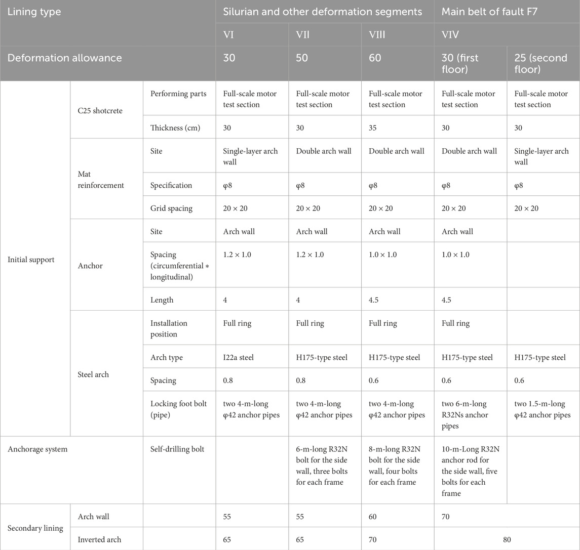
Table 4. Composite lining support parameters of double-line tunnel in large deformation section.
4.3.6 Large-stiffness secondary lining
The secondary lining adopts large stiffness reinforced concrete, the arch wall is 55–70 cm, the inverted arch is 65–80 cm thick, and the thickness of the inverted arch is greater than 10 cm of the arch wall.
4.4 Construction control measures
During the construction process, the deformation control of a tunnel surrounded by squeezing rock can be implemented by using micro-bench excavation to control the stress release, rapid non-blasting excavation while reducing the disturbance to the surrounding rock, rapid support of unmanned vertical arch drilling and bolting and grouting integration operation, timely grasping of the support deformation and stress situation through monitoring and measurement, and timely implementation or adjustment of deformation control measures.
4.4.1 Excavation by micro-bench method
Reducing the benching length can shorten the closure time of an inverted arch and help control the deformation. The large deformation section adopts the micro-bench method, deformation sections I and II adopt the three-bench temporary support method, and deformation sections III and IV adopt the three-bench temporary inverted arch method. The excavation should be performed manually with a machine (cantilever road header) as much as possible, and the core soil can be reserved if necessary. The benching length should be 3–5 m, and the distance between the initial support of the inverted arch and the face of the tunnel should not be more than 15 m.
1. The grade V surrounding rock of each excavation cycle and support footage of the upper bench should not be greater than the spacing of one steel frame, and the excavation support footage of each cycle of side wall should not be more than two pieces.
2. Before the excavation of the inverted arch, the steel frame lock foot anchor pipe must be completed, and the excavation footage per cycle should not be greater than 3 m.
3. The distance between the closed position of the inverted arch and the tunnel face should not be more than 35 m, and the distance between the secondary lining and the tunnel face should not be more than 70 m.
4.4.2 Cantilever boring machine milling construction technology
1. Construction process
In the construction of a tunnel surrounded by squeezing rock, the traditional drilling and blasting method is generally used for excavation. This method causes great vibration damage to the surrounding rock, especially to the loose circle of surrounding rock. The deformation of the surrounding rock in the later stage is difficult to control. Excessive support deformation occurs, arches exceeding the specified limitations must often be changed, and the excavation process is cumbersome, making the construction progress uncontrollable. Further, many workers are present at the tunnel face during blasting excavation construction, and the safety risk is high.
To ensure construction safety, quality, and progress, the large deformation section of the new Wushaoling Tunnel was excavated by using a cantilever boring machine. Through the advanced geophysical exploration and drilling of the working face, the condition of the rock surrounding the working face could be understood. In addition, considering the site construction conditions, the corresponding cantilever road header was selected to cut and excavate the upper benching. In the rear, the excavator, loader, and slag truck were used to receive the material directly, and the cut slag material was transported to the designated position. After the excavation of the upper benching had been completed, the lower was cut and excavated (with synchronous completion of slag discharge), and the operation of the upper benching arch frame, setting of the advanced support, and locking of the foot were conducted simultaneously. After the excavation of the lower benching had been completed, the road header was returned to the parking area. During the construction of the inverted arch excavation, the initial support and monitoring measurement of the lower benching were continued, so as to complete the excavation construction of the entire large section tunnel. The on-site construction of the cantilever road header is shown in Figure 9.
① When the self-stability of the rock surrounding the working face is determined to be relatively good, the upper benching is divided into two parts for excavation. According to the rotation direction of the cutting head, the cutting sequence is strictly performed according to the scheme, and cutting at will is not allowed. The cutting head of the cantilever road header rotates clockwise, and the cutting is performed in a bottom-up order. If the joint fissure is more developed in the surrounding rock, it should be selected to cut gradually along the rock joint. After cutting the main part of the lofting contour, the contour line is cut and trimmed.
② When the self-stability of the surrounding rock of the tunnel face is poor, the core soil is reserved for the excavation of the upper benching. The reserved size is generally 3–3.5 m in the transverse direction, 3–4 m in the longitudinal direction, and 3.5–4 m high. The front end of the cutting head of the cantilever road header to the front end of the shovel plate is approximately 2.2 m (when the cutting arm is flat), and the range from the top of the core soil to the vault is 2 m using a crushing hammer. Both sides of the core soil and the core soil itself are constructed by a cantilever road header. The core soil is excavated from the bottom to the top, and the footage should not be more than 1 m at a time. The crushing hammer breaks the rock by adjusting the striking force and the machine frequency.
2. Advantages
① The milling excavation method involves going back and forth, layer by layer, from left to right by cutting picks. An operation cantilever can realize accurate excavation according to the design contour, and the overbreak and underbreak can be easily controlled (to 10–15 cm). Compared to drilling and blasting, mechanical cutting disturbs the surrounding rock less, and the range of the loose circle of surrounding rock is small, which is beneficial to the deformation control of the surrounding rock.
② In large-section mechanized construction, the construction progress is fast, the number of face workers and labor intensity can be reduced, and safety can be enhanced.
③ Excavation, slag discharge, and dust reduction can be performed simultaneously to save process conversion time and ensure efficient construction processes in the tunnel.
④ Compared with the drilling and blasting method, the cantilever road header can significantly improve the construction efficiency index.
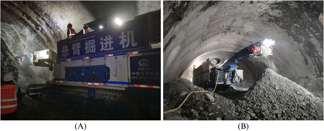
Figure 9. Photographs of upper benching cantilever road header construction: (A) excavation of upper benching and (B) rapid slag discharge.
4.4.3 Unmanned vertical arch drill bolt-grouting integrated operation
Tunnel support is a high-risk link in the construction of large deformation tunnels. The traditional manual construction method has the disadvantages of low operation efficiency and great potential safety hazards to the operators. During the construction process, phenomena such as falling blocks and collapses can occur due to untimely support. To reduce construction safety hazards, reduce labor intensity, improve work efficiency, and improve construction quality, an SCDZ134 intelligent arch trolley was used for upper benching support during the construction process and tunnel construction operations such as arch installation, integrated construction of drilling, anchoring, grouting, locking foot and anchor pipes, automatic and accurate positioning, 3D contour scanning, automatic identification of overbreaks and under-breaks, intelligent arch installation, information management, explosive loading, auxiliary skidding, auxiliary measurement, equipment installation, ventilation pipe operation, quality inspection, and defect repair were conducted. Figure 10 shows the on-site “unmanned” vertical arch drill anchor-grouting integrated operation.
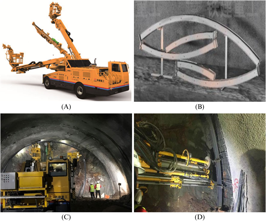
Figure 10. Photographs of “unmanned” vertical arch drilling, anchoring, and injection integrated operation: (A) SCDZ134 intelligent arch truss; (B) steel arches; (C) installation of new steel arch frames; and (D) integrated construction of locking foot steel pipe drilling, installation, and injection.
In unmanned vertical arch construction, by changing the connection mode between the steel arch segments, optimizing the alternative scheme of longitudinal connecting bars and steel mesh, and using a drill-anchor-grouting integrated trolley to implement the vertical arch operations, the requirements of few people and an unmanned vertical arch process can be realized. Thus, the labor intensity and number of workers can be reduced, and steel arches can be set up quickly and safely. Field construction shows that the efficiency of vertical arch construction can be greatly improved using this approach. The number of vertical arch operators can be reduced from 9 to 3, and the time required to install one arch can be reduced from 1.5–2 h–1 h.
4.4.4 Construction time of secondary lining
The squeezing rock surrounding and tunnels has obvious rheological properties, with large deformation, a high deformation rate, and large, long-duration stress on the supporting structure. The squeezing load is carried by the surrounding rock and lining. If the secondary lining is applied too early, the structure will bear too much load and be crushed. If the construction is too late, the primary support may become unstable or even collapse; thus, the construction time of the secondary lining is an urgent and clear problem to be solved on site (Li et al., 2022).
During the construction of the existing Wushaoling Tunnel, the control index of the second lining construction time had a deformation rate of 3–5 mm/d in the F7 and Silurian phyllite section. For the second lining construction of Lanzhou–Chongqing Railway, the deformation rate (not less than the average value over 7 days) is ≤2 mm/d for a double line and ≤1 mm/d for a single line. Combined with the specifications of China Railway Corporation (2019) regarding the timing of the construction of the secondary lining in a tunnel with squeezing surrounding rock, the secondary lining should be constructed after the deformation of the surrounding rock and the primary support is basically stable. The basic stability of deformation should be consistent with the following characteristics: the deformation rate decreases significantly and tends to ease; when there is no experience; the deformation rate (7 days average) can be less than 1 mm/d for small and medium spans and less than 2 mm/d for large spans and above; and the secondary lining can be strengthened.
4.4.5 Deformation management benchmark of the construction process
In contrast to general surrounding rock, the deformation displacement and velocity are used to monitor and measure the squeezing surrounding rock. The grade of deformation management in railway tunnel construction is presented in Table 5, and the deformation management countermeasures are listed in Table 6. When the measured data are close to the values specified in the table, or the concrete surface has obvious cracks, immediate reinforcement measures should be taken, and the construction method or design parameters should be changed.
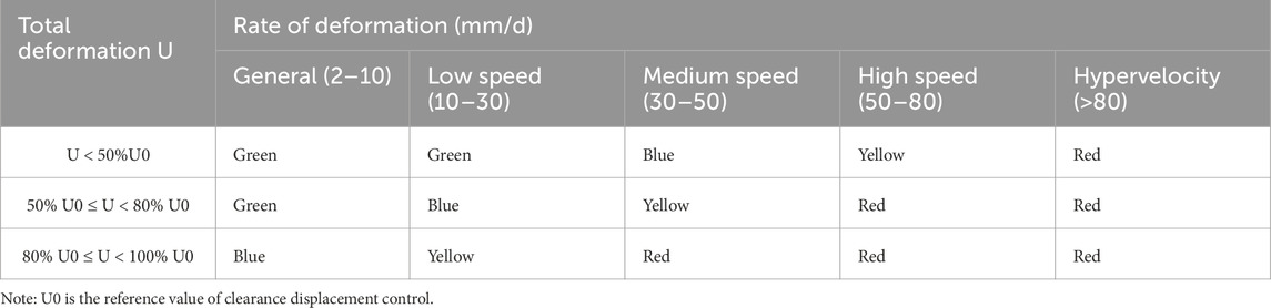
Table 5. Classification of construction deformation management grades of rock surrounding and squeezing a railway tunnel.
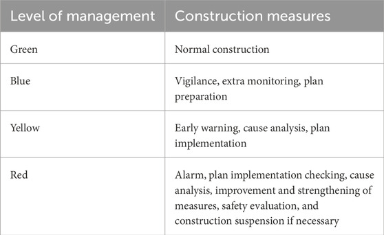
Table 6. Deformation management countermeasures for rock surrounding and squeezing a railway tunnel.
4.5 Deformation control effect
Taking the tunnel deformation as the main investigation target, the layout of the measuring points is shown in Figure 11. The deformation of the tunnel is the largest in the displacement of the middle-benching side wall (S2-1, S2-2). Therefore, the deformation of the new Wushaoling Tunnel was assessed with the displacement of the middle-benching side wall as the target. A typical deformation time history curve is shown in Figure 12. Figure 13 demonstrates that the time–history curve of tunnel deformation conforms to the typical deformation law of rapid growth–deceleration growth–gradual stability. However, as the deformation grade increases, the tunnel deformation and deformation stability time gradually increase. Because of the double-deck timbering and other measures adopted in the section of grade DⅣ deformation, the total deformation is slightly less than that in the section of grade DIII deformation.
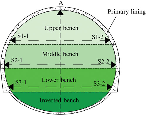
Figure 11. Layout of deformation measurement points.
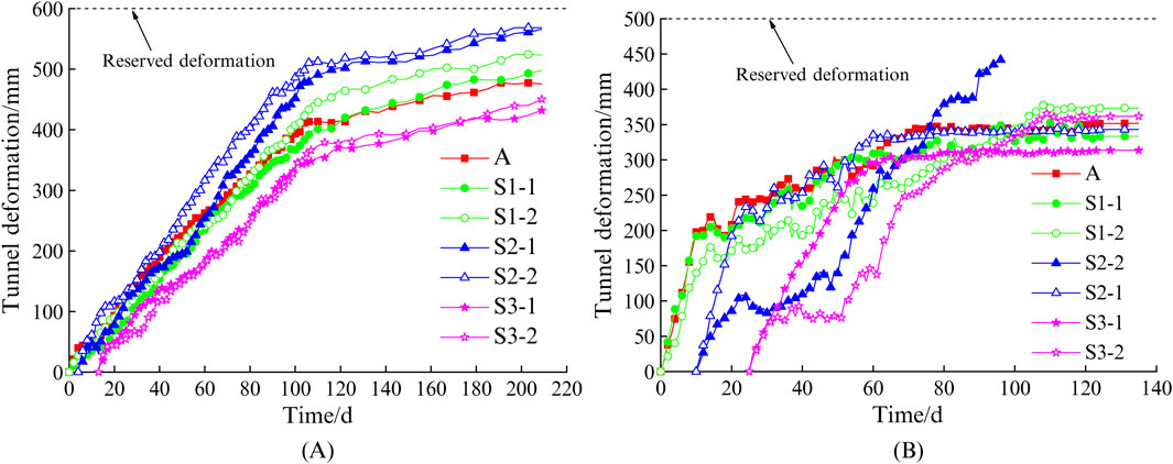
Figure 12. Time history curves of tunnel deformation: (A) DK171 + 525, section of grade DIII deformation, and (B) DK169 + 780, section of grade DII deformation.
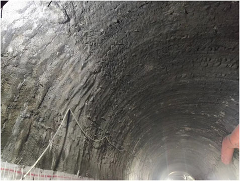
Figure 13. In-situ effect of initial support (Grade DⅢ deformation).
Statistics showed that the maximum deformations of the grade I, II, II, and IV deformation sections of the new Wushaoling Tunnel are 298, 495.6, 589.7, and 536.4 mm, respectively. These findings demonstrate that the reserved deformation of the tunnel has been fully utilized, and no problem of the initial supports exceeding the specified limitations exists. Although some bulging occurs in the initial support, the tunnel deformation is effectively controlled and the support effect is good. Photographs of the initial support on site are provided in Figure 13.
5 Conclusion
Comparative analysis of the design and construction of the new and existing Wushaoling tunnels revealed that for the deformation control of a tunnel surrounded by squeezing rock, the previous problems are mainly inaccurate determination of the deformation potential of the squeezing surrounding rock and an unclear design load, resulting in insufficient support strength. Based on years of construction experience and lessons related to tunnels surrounded by squeezing rock, the new Wushaoling Tunnel adopts the large deformation control technology system of strengthening classification, cavern optimization, support strengthening, moderate release, micro-benching excavation, and mechanized construction to control the deformation of the surrounding rock effectively. The main conclusions include the following points:
1. Based on the classification of surrounding rock deformation, the deformation grade is determined according to the deformation potential, strength–stress ratio of the rock mass, and relative deformation, and the deformation pressure on the structure is determined according to the deformation grade. The load–structure method is used to compare and analyze the stress and deformation characteristics of different section shapes. The results show that the stress state of the structure can be effectively improved by expanding the curvature of the side wall and inverted arch. A four-center circular section can be designed whose cross-section is closer to a circle. By increasing the depth of the inverted arch, it can be applied to tunnels with squeezing surrounding rock of different deformation grades.
2. When designing the supporting structure, it should be based on the principle of an anti-release combination, pre-controlled release, support strengthening, surrounding rock reinforcement, stress release, and other aspects of control. These additional aspects mainly include advanced support strengthening; using a long, medium, and short anchorage system; increasing the support stiffness; increasing the reserved deformation; and utilizing multi-layer supports.
3. The micro-benching method is used to shorten the closure time of the inverted arch, which plays a key role in controlling the deformation. During the construction process, by setting temporary horizontal braces or temporary inverted arches, a temporary closed structure can be formed to control the deformation.
4. According to the characteristics of large squeezing deformation, the principle of quick excavation and quick support should be implemented during construction. Weak blasting or non-blasting methods, such as mechanical excavation by a cantilever road header, are used to reduce the disturbance to the surrounding rock. In addition, an intelligent arch trolley is used to realize the integrated operation of an anchor and the grouting of an unmanned vertical arch drill.
5. The maximum deformations of the supports of the grade DI, DII, DIII, and DIV deformation sections of the new Wushaoling Tunnel are 298, 495.6, 589.7, and 536.4 mm, respectively, which do not exceed the reserved deformation. Although some of the initial supports on site have bulged and cracked, the tunnel deformation is generally controllable and the support effect is good.
Author contributions
CH: Supervision, Writing–review and editing. SL: Investigation, Writing–original draft. GL: Supervision, Writing–review and editing. TY: Investigation, Writing–original draft. XW: Investigation, Writing–original draft.
Funding
The author(s) declare that financial support was received for the research, authorship, and/or publication of this article. This work was supported by the National Natural Science Foundation of China under Grant No. 52178391, the State Key Laboratory of Mechanical Behavior and System Safety of Traffic Engineering Structures under Grant No. ZZ2021-09.
Conflict of interest
Authors CH, SL, TY, and XW were employed by China Railway 15th Bureau Group Co., Ltd. Authors CH, SL, TY, and XW were employed by China Railway 15th Bureau Group No. 5 Engineering Co., Ltd. Author GL was employed by China Railway First Survey and Design Institute Group Co., Ltd.
Publisher’s note
All claims expressed in this article are solely those of the authors and do not necessarily represent those of their affiliated organizations, or those of the publisher, the editors and the reviewers. Any product that may be evaluated in this article, or claim that may be made by its manufacturer, is not guaranteed or endorsed by the publisher.
References
Arora, K., Gutierrez, M., Hedayat, A., and Cruz, E. C. (2023). Time-dependent behavior of the tunnels in squeezing ground: an experimental study. Rock Mech. Rock Eng. 54, 1755–1777. doi:10.1007/s00603-021-02370-w
China Railway Corporation (2019). Q/CR 9512-2019 Code for tunnelling squeezing rocks. Beijing: China Railway Publishing House.
Dwivedi, R. D., Singh, M., Viladkar, M. N., and Goel, R. K. (2013). Prediction of tunnel deformation in squeezing grounds. Eng. Geol. 161, 55–64. doi:10.1016/j.enggeo.2013.04.005
Guan, K., Zhu, W., Liu, X., Wei, J., and Niu, L. (2020). Re-profiling of a squeezing tunnel considering the post-peak behavior of rock mass. Int. J. Rock Mech. Min. Sci. 125, 104153. doi:10.1016/j.ijrmms.2019.104153
Guo, X. (2019). Study on the classification control technology on deformation of soft rock tunnel under high geo-stress and the construction time of secondary lining. Beijing Jiaotong University. [PhD thesis]. [Beijing (China)].
Guo, X., Wang, B., Yu, W., Wang, Z., and Wang, Y. (2023). Experimental study on mechanical characteristics of yielding (combined) bolt in extrusion large tunnel deformation. Chin. J. Highw. 36 (6), 180–189. doi:10.19721/j.cnki.1001-7372.2023.06.016
He, M., Wang, B., Tao, Z., Qiao, Y., and Xiao, Y. (2021). Axial compression behavior of adaptive steel arch joint for large-deformation tunnels. Chin. J. Highw. Transp. 34 (5), 1–10. doi:10.19721/j.cnki.1001-7372.2021.05.001
Kang, H., Jiang, P., Wu, Y., and Gao, F. (2021). A combined “ground support-rock modification-destressing” strategy for 1000-m deep roadways in extreme squeezing ground condition. Int. J. Rock Mech. Min. Sci. 142, 104746. doi:10.1016/j.ijrmms.2021.104746
Li, G., and Li, N. (2018). Discussion of tunnelling in squeezed surrounding rock. Mod. Tunn. Technol. 55 (1), 1–6. doi:10.13807/j.cnki.mtt.2018.01.001
Li, G., Li, N., Ding, Y., and Liu, Z. (2022). Study on identification and design method of squeezing surrounding rock tunnel. J. Chin. Railw. Soc. 44 (3), 24–38. doi:10.3969/J.ISSN.1001-8360.2022.03.002
Li, G., Liu, Z., and Zhu, Y. (2015). On the large squeezing deformation law and classification criteria for the Lanzhou-Chongqing railway tunnels in soft and high geostress rocks. Mod. Tunn. Technol. 52 (1), 62–68. doi:10.13807/j.cnki.mtt.2015.01.009
Li, G., Xiong, C., and Li, N. (2019). Research on the control technology of squeezing surrounding rock tunnel based on deformation potential. J. Railw. Eng. Soc. 36 (10), 77–81 + 106.
Liu, W., Chen, J., Luo, Y., Chen, L., Shi, Z., and Wu, Y. (2021). Deformation behaviors and mechanical mechanisms of double primary linings for large-span tunnels in squeezing rock: a case study. Rock Mech. Rock Eng. 1, 2291–2310. doi:10.1007/s00603-021-02402-5
Liu, Z., and Li, G. (2020). The calculation method of surrounding rock pressure in squeezing rock tunnel. J. Railw. Eng. Soc. 37 (11), 69–76.
Liu, Z., Zhu, Y., Li, W., and Liu, P. (2008). Mechanism and classification criterion for large deformation of squeezing ground tunnels. Chin. J. Geotech. Eng. 5, 690–697. doi:10.3321/j.issn:1000-4548.2008.05.012
Ma, D., Sun, Y., Wang, W., and Jin, L. (2021). Key technologies for controlling large deformation of soft rock tunnels with high geostress. Tunn. Constr. 41 (10), 1634–1643. doi:10.3973/j.issn.2096-4498.2021.10.002
Majumder, D., Viladkar, M. N., and Singh, M. (2022). Numerical modelling of tunnels excavated in squeezing ground condition: a case study. Arab. J. Sci. Eng. 48 (4), 4657–4673. doi:10.1007/s13369-022-07098-5
Ramoni, M., and Anagnostou, G. (2010). Thrust force requirements for TBMs in squeezing ground. Tunn. Undergr. Space Technol. 25 (4), 433–455. doi:10.1016/j.tust.2010.02.008
Sun, S. (2012). Characteristics of soft rock tunnels and large deformation control technology in the Lanzhou-Chongqing railway. Mod. Tunn. Technol. 49 (3), 125–130. doi:10.13807/j.cnki.mtt.2012.03.020
Tb10003-2001 Code for design of railway tunnel (2016). China national railway administration. Beijing, China: China railway publishing house.
Tian, S., Wu, K., Liu, D., Wang, M., and Wang, Z. (2021). Study on active support technology for deformation control of tunnels in soft surrounding rock. J. Chin. Railw. Soc. 43 (6), 158–164. doi:10.3969/j.issn.1001-8360.2021.06.021
Wang, R., Liu, Z., Liu, Y., and Xu, Z. (2020a). Optimization of span-ratio of large-span tunnel in squeezing surrounding rocks. Mod. Tunn. Technol. 57, 713–720. doi:10.13807/j.cnki.mtt.2020.S1.095
Wang, X., Lai, J., Garnes, R. S., and Luo, Y. (2019). Support system for tunnelling in squeezing ground of Qingling-Daba mountainous area: a case study from soft rock tunnels. Adv. Civ. Eng. 2019, 8682535. doi:10.1155/2019/8682535
Wang, Y., Ding, W., Liu, Z., Wang, Z., and Li, W. (2020b). Classification standard of large deformation and construction time of second lining in Muzhailing tunnel. Chin. J. Undergr. Space Eng. 16 (4), 1116–1122.
Xu, J., Xie, X., Tang, G., Zhou, B., Xu, D., and Huang, Y. (2023). A new adaptive compressible element for tunnel lining support in squeezing rock masses. Tunn. Undergr. Space Technol. 137, 105124. doi:10.1016/j.tust.2023.105124
Yang, B., Liu, T., Liu, Z., Li, N., and Duo, S. J. (2023). Cross-section shape optimization design of railway tunnel in squeezing rock based on deformation classification. Tunn. Constr. 43, 344. doi:10.3973/j.issn.2096-4498.2023.S1.040
Zhou, Z., Chen, Z., He, C., Jiang, C., and Li, T. (2024). A solution method for tunnel supporting structure system incorporating the active control of surrounding rock deformation. Int. J. Geomech. 24 (1), 04023243. doi:10.1061/IJGNAI.GMENG-8652
Keywords: tunnel, squeezing surrounding rock, deformation classification, deformation control, micro-bench method
Citation: Huang C, Li S, Li G, Yao T and Wu X (2024) Reform of deformation control technology for railway tunnels with squeezing surrounding rock: case study of the new and existing Wushaoling tunnels in China. Front. Earth Sci. 12:1438425. doi: 10.3389/feart.2024.1438425
Received: 26 May 2024; Accepted: 15 August 2024;
Published: 26 September 2024.
Edited by:
Haizuo Zhou, Tianjin University, ChinaReviewed by:
Xiaoxuan Yu, Tianjin University, ChinaLichen Li, China University of Geosciences Wuhan, China
Copyright © 2024 Huang, Li, Li, Yao and Wu. This is an open-access article distributed under the terms of the Creative Commons Attribution License (CC BY). The use, distribution or reproduction in other forums is permitted, provided the original author(s) and the copyright owner(s) are credited and that the original publication in this journal is cited, in accordance with accepted academic practice. No use, distribution or reproduction is permitted which does not comply with these terms.
*Correspondence: Shaohua Li, enoxNmxpc2hAeWVhaC5uZXQ=