 Lin Zhao
 Lijun Zhang1
 Shuoliang Wang
94% of researchers rate our articles as excellent or good
Learn more about the work of our research integrity team to safeguard the quality of each article we publish.
Find out more
ORIGINAL RESEARCH article
Front. Earth Sci. , 02 July 2024
Sec. Economic Geology
Volume 12 - 2024 | https://doi.org/10.3389/feart.2024.1418821
This article is part of the Research Topic Efficient Exploration and Development of Unconventional Natural Gas View all 8 articles
Using subterranean rock cores as samples, the impact of depletion exploitation and cyclic gas injection on the occurrence and dynamic utilization of condensate oil and the damage to reservoirs were studied. Initially, the internal pore structure of the rock core was analysed using computer tomography (CT), followed by depletion and cyclic gas injection experiments, with in-situ CT scanning of the samples. The results indicate that under different fracture apertures, condensate oil exhibits wave flow and slug flow states. The production effectiveness of cyclic gas injection is significantly superior to depletion exploitation production, with condensate oil saturation decreasing by over 30%. During cyclic gas injection, fractures serve as the main flow channels, with condensate oil being extracted first. In cyclic gas injection, the most significant effect is seen during the first injection, with a decrease in oil saturation of around 3%. Subsequent injections show decreases of approximately 1% and 0.5% in oil saturation respectively. As the gas injection volume increases, the extent of cumulative production rate improvement also gradually increases; however, once the injection volume reaches the reservoir pressure, the rate of cumulative production rate improvement will gradually decrease. These findings provide technical support for optimizing the development mode of condensate gas reservoirs, clarifying the seepage law of condensate oil and gas, and providing technical support for the efficient development of fractured condensate gas reservoirs.
Condensate gas reservoir refers to a special gas reservoir where the formation pressure lies between the critical pressure under original formation conditions and the maximum dew point pressure (Nasriani et al., 2015; Long et al., 2023; Dorhjie et al., 2024). Condensate gas reservoirs exhibit the following characteristics: firstly, they exist in the reservoir in both adsorbed and free states, with various accumulation methods. Secondly, the reservoir contains complex pore structures such as nano-scale intra-granular pores, inter-granular pores, and micro-scale fractures. Lastly, due to the abundant presence of micro-scale fractures, condensate gas reservoirs involve complex multi-scale phase changes, leading to significant differences in phase behavior compared to conventional phase changes (Hosseinzadegan et al., 2023; Wang, 2023). Before reservoir exploitation, condensate gas reservoirs remain in a gaseous state under the influence of formation temperature and pressure. As the gas reservoir is developed, the formation pressure gradually decreases, and when it reaches and falls below the dew point pressure, a gas-liquid two-phase zone appears (Liu et al., 2024). The precipitation of condensate oil increases the permeability resistance of the surrounding reservoir rock, resulting in a sharp decline in the overall gas reservoir production. Therefore, studying the phase behavior of condensate gas reservoirs in formations with continuously changing pressures is of crucial importance for their development.
Choosing the appropriate method for condensate gas reservoir exploitation is crucial for the recoveries of condensate gas and condensate oil, directly impacting the final economic benefits. During the depletion exploitation phase, when the pressure drops to the maximum anti-condensation pressure, the condensate oil saturation reaches its peak. Despite triggering retrograde condensation after dropping to the secondary dew point pressure, the decrease in condensate oil saturation is relatively small (Jing et al., 2023). The production of condensate oil and the increase in saturation lead to a significant decrease in the relative gas permeability of the reservoir, reducing the gas well productivity. At the same time, condensate oil precipitates and accumulates in the wellbore area, complicating the wellbore conditions, reducing production efficiency, and in severe cases, leading to well shutdown (Salmani et al., 2020; Hosseinzadegan et al., 2023). The principle of cyclic gas injection for exploitation involves periodically injecting high-pressure gas (dry gas, surface-separated gas) to displace condensate oil in wet gas, aiming to increase reservoir pressure and prevent retrograde condensation (Kumar et al., 2015; Zhang et al., 2020; Jiang, 2023). When condensate oil reserves are large and content is high, employing pressure maintenance methods can reduce condensate oil losses. The effectiveness and rationality of maintaining formation pressure depend on factors such as condensate oil content, oil and gas reserves, burial depth, pressure, reservoir homogeneity and connectivity, drilling techniques, high-pressure gas injection processes, and other factors (Faramarzi and Sadeghnejad, 2020; Reis and Carvalho, 2022).
The PVT (Production verification test) experiment is currently a common method for simulating the production conditions of condensate gas (Passoni et al., 2024). Guo et al. (2020) studied the effect of different gas injection methods on the flow pattern of condensate gas through PVT experiments. Wang et al. (2022) used a visual PVT device to study the retrograde condensation phenomenon of condensate gas with temperature/pressure changes, revealing that the dew point pressure of condensate gas in the Wenchang 9-2 low-condensate gas field is close to the reservoir pressure. With the development of artificial intelligence technology, Alarouj et al. (2020) established a large database containing over 700 gas-condensate oil samples and a new model for calculating dew point pressure, which significantly outperforms the simulation results of existing state equations in terms of accuracy. Despite the achievements in AI (Artificial Intelligence) prediction, it is still limited by the quality and size of the dataset. Calculation based on state equations is another method to determine the behavioural characteristics of condensate gas phase. Shi et al. (2015) proposed a new equation for gas condensate well deliverability, considering the phase behaviour of gas condensate fluids in the wellbore. The results indicate that neglecting wellbore phase behaviour can lead to inaccurate predictions of gas and condensate production, and validation cases show good agreement between the new model and actual data. Traditional PVT experiments and AI-based methods both fail to consider the impact of porous media on the behaviour of condensate gas phase. Jing et al. (2023) dynamically characterised the phase transition process of condensate gas in porous media during the depressurisation depletion process using real-time CT scanning and digital rock technology, suggesting that the change in condensate oil content within the porous media occurs synchronously throughout the depletion process. These studies demonstrate the influence of porous media on the phase behaviour of condensate gas, yet the phase transition characteristics of condensate gas in fracture and matrix systems have not been considered.
In summary, the research on the phase transition mechanisms of condensate gas in porous media, especially the dynamic phase evolution of condensate oil in complex fracture systems, under different production processes still requires further refinement. This study focuses on the rock cores in the target area, investigating the dynamic evolution of multi-component condensate gas phases in porous media. The condensate gas components in actual condensate reservoirs were blended and subjected to PVT testing. The CT scan data were processed using PerGeos, and the pore structure of the rock core was analysed. Depletion and cyclic gas injection (CGI) experiments were conducted in the rock core, obtaining the distribution of condensate oil and gas at different pressures using an in-situ CT system. Ultimately, the phase characteristics of condensate oil in fractured porous media were described, and the formation process and mechanism were summarised, comparing the effects of different exploitation methods on the development of condensate gas reservoirs.
By combining samples of oil and gas collected on-site from the target blocks, corresponding mixing work was carried out. The composition of the oil and gas samples in the on-site separators is shown in Table 1.
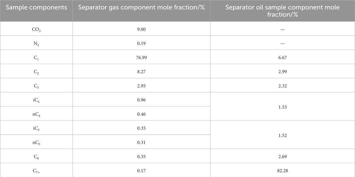
Table 1. Oil and gas components in the separator.
In the research area, the density of rock fractures exhibits diversity, ranging from 1 to 15 fractures per meter. The fractures vary widely in aperture, covering a range from a few micrometers to several hundred micrometers, with a predominance of high-angle fractures followed by vertical ones. Low-angle and horizontal fractures are relatively less abundant (Figure 1). The wettability is water wet, and the contact angle is 67.8°.
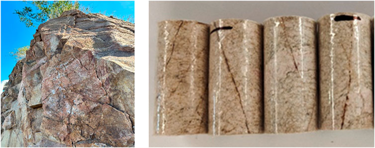
Figure 1. Outcrop rock samples and plunger core samples in the study area.
Field coring and logging results from the target block and adjacent blocks indicate that the upper weathering zone of the target block shows strong dissolution, severe weathering, and mainly irregularly developed weathering mesh fractures, densely interwoven like a spider web. The weathering degree gradually weakens towards the lower part, with strong tectonic stress, mainly developing structurally distributed fractures resembling layers. The reservoir space includes macro fractures, small to medium fractures, micro fractures, as well as intergranular pores, dissolution pores, etc., resulting in a reservoir with multi-scale flow spaces and complex pore-throat structures.
The experimental fluid samples were prepared under formation pressure of 46.90 MPa and formation temperature of 138°C according to the production gas-oil ratio of 1420.89 m3/m3. The sample preparation and PVT analysis method refer to the national standard GB/T26981-2020 “Reservoir Fluid Physical Property Analysis Method.”
(a) Using the mixed reservoir fluid, the actual fractured core was raised to reservoir temperature and maintained for 3–4 h.
(b) Then a system pressure of 50 MPa was established using methane gas.
(c) Methane in the model was replaced with mixed condensate gas to saturate the actual fractured core under reservoir temperature and pressure conditions. Back pressure was slowly reduced at the set pressure drop rate to initiate simulated depletion exploitation.
(d) The production of oil and gas at the outlet was recorded, and the production dynamics were analyzed.
(e) The CT raw data was processed using PerGeos software to determine the distribution of condensate oil in the rock fractures and pores. Condensate oil saturation is the percentage of the ratio of oil volume in the effective pores in the core to the effective pore volume of the rock (Figure 2).
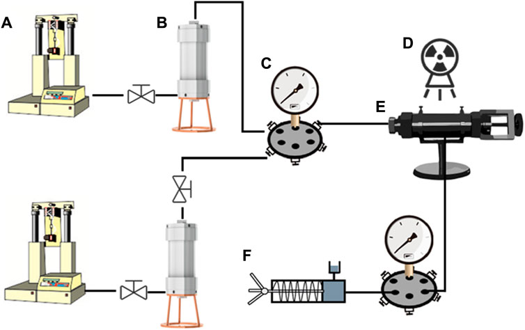
Figure 2. Experimental flow, (A): constant speed and constant pressure pump, (B): intermediate vessel, (C): six-way valve, (D): real-time CT device, (E): gripper, (F): hand pump.
(a) Preparation steps were the same as depletion exploitation.
(b) The experimental fluid in the fractured core was saturated under reservoir temperature and pressure conditions with methane from the mixed condensate gas. Back pressure was slowly reduced at the set pressure drop rate to initiate simulated depletion exploitation until 30 MPa.
(c) Associated gas was injected back to reservoir pressure and maintained for half an hour, then production from two production outlets was simultaneously produced, repeating this process three times.
(d) Post-processing steps were the same as depletion exploitation.
Traditional methods for studying the behavior of condensate gas phase typically involve experiments to determine the relationship between the pressure, temperature, and volume of the condensate gas. Constant Composition Expansion (CCE) and Constant Volume Depletion (CVD) are the most commonly used experimental methods in PVT units, used to simulate the phase behavior changes of condensate gas reservoirs during development. To simulate the fluid component parameters of the target reservoir block, corresponding separator oil and gas samples were mixed. By conducting CCE and CVD under reservoir temperature and pressure conditions, the laboratory mixed fluid samples closely match the PVT experimental results of the target block oil and gas samples (Figure 3). These results indicate that the mixed fluid samples are representative, therefore, subsequent microscopic experiments will use this oil sample for testing.
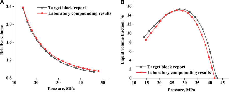
Figure 3. Results of PVT experiments (A) Comparison of CCE experimental results, (B) Comparison of CVD experimental results.
Although these experiments can provide essential high-pressure physical properties of condensate gas, they also have limitations. Traditional PVT experiments typically only provide macroscopic properties of the condensate gas and cannot reveal the behavior of condensate gas at a microscopic scale within porous media. Understanding and predicting the productivity and recovery efficiency of condensate gas reservoirs heavily rely on these microscopic behaviors.
A representative elementary volume (REV) with voxel dimensions of 400 × 400 × 400 was extracted from the CT scan data of the core. However, due to external disturbances during the scanning process, the resulting images had issues such as uneven brightness, low contrast, and high noise levels. To enhance the image quality, brightness, contrast, and filtering processes were required (Wang et al., 2024).
By sequentially stacking multiple layers of 2D grayscale images, a 3D grayscale image consistent with the actual core was obtained. The watershed algorithm was used for image segmentation (Patmonoaji et al., 2020). The traditional watershed algorithm is a morphological segmentation method based on topological theory. In morphological segmentation methods, images are typically treated as terrain surfaces, with each grayscale level corresponding to a contour line. This approach establishes boundaries known as “watersheds” around each local minimum value in the image, making it straightforward to estimate image gradients and locate gradient peaks for segmentation. Given the significant grayscale variations at the phase edges of the core image, the gradient image effectively describes these variations (Wang et al., 2023).
Following the segmentation process, a 3D digital core model is created, as shown in Figure 4. Lower grayscale values represent fractures within the core, while higher values represent rock matrix particles. In the binary 3D digital core model, the matrix is transparent, and the pore space is displayed in blue. The fracture structures with good connectivity within the rock matrix are clearly visible, presenting a sheet-like distribution. Different colours in the 3D pore-fracture spatial distribution map represent different pore clusters.
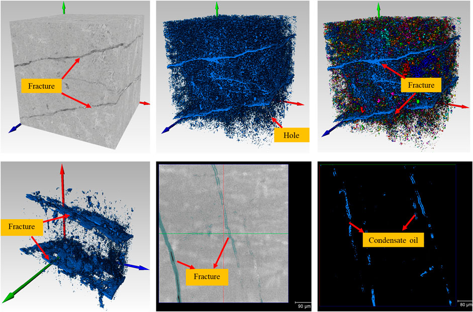
Figure 4. Pore structure analysis and residual oil distribution of 3D and 2D digital cores.
Based on the characteristics of rock pore structure and the flow behavior of fluids within them, the internal structure is defined as a dual-porosity medium, consisting of fractures and matrix as two major systems. By utilizing CT image threshold segmentation to identify the position of fractures, the blue area represents condensed oil. In the 3D residual oil distribution map, the shape of the condensed oil distribution aligns with the shape of sheet-like fractures, indicating that fractures serve as the main flow channels for condensed oil. Additionally, wave-like flow of condensed oil is observed in large fractures (Figure 5).
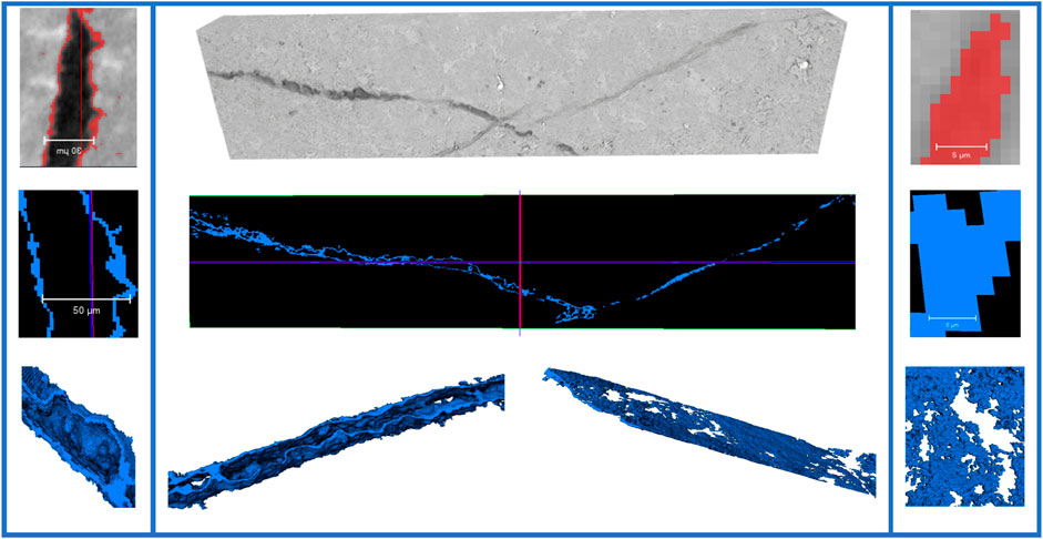
Figure 5. Condensate fugacity flow pattern in fractures in 3D core model (wave flow on the left, segment plug flow on the right).
A rock core region containing two intersecting fractures with different apertures was extracted from the rock core data volume (Table 2), with the aperture range of small fractures being 3–8 μm and wide fractures being 20–50 μm. Within the distribution of condensed oil, distinct phenomena of segmented flow and wave-like flow were observed in fractures, with segmented flow predominantly in small fractures and wave-like flow in wide fractures. Segmented flow in small fractures consists of isolated segments without trailing liquid droplets, with a thin oil film covering the fracture wall and surrounding the segments. On the other hand, wave-like flow in wide fractures was influenced by the interaction forces between oil and gas phases and the fracture wall, resulting in a wave-like shape of condensed oil on the fracture wall with significant differences in film thickness between the top and bottom of the fracture.
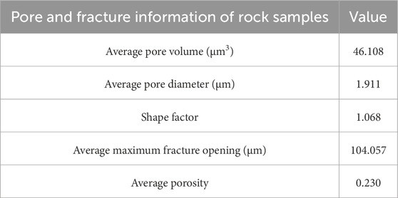
Table 2. Pore-fracture statistical results of digital core.
The existence characteristics of condensed oil in porous media and fractures are based on two fundamental theories: adsorption theory and bound water film theory. Adsorption refers to the continuous accumulation of gas or vapor molecules on the solid surface acting as an “adsorbent” until reaching thermodynamic equilibrium (Dąbrowski, 2001). Bound water refers to a layer of water film adsorbed on the surface of rock particles due to molecular gravity and electrostatic forces, divided into adsorbed water within the water film and thin film water on the outer layer of the water film (Hu et al., 2024).
When the pressure is below the dew point pressure, condensed oil droplets precipitate and adsorb on the surface of rock particles or suspend in the condensed gas. As pressure decreases, the droplets grow and coalesce, transitioning the liquid on the surface into a continuous state and initiating gradual flow. The external layer of condensed oil is influenced not only by molecular forces but also by external forces such as gravity, pressure differential, and friction with gas. Pressure differential has the greatest impact on the flow of condensed oil, where the flow of condensed oil along the outer layer of the pore wall is primarily due to pressure differential, directed towards the pressure drop, resulting in the phenomenon of “wave-like flow” of condensed oil (Nabae et al., 2020).
When an adsorption layer forms on the surface of a wide fracture in a condensed gas system, the thickness of the adsorption layer compared to the pore space can be negligible. However, in nanometer pores or microfractures, the thickness of the adsorption layer cannot be ignored. There is a positive relationship between the aperture of fractures and the ratio of condensed oil volume in fractures to total condensed oil volume, meaning that the smaller the fracture volume, the more difficult it is for the condensed gas to mobilize the condensed oil within the fracture. These condensed oils come into contact, merge, and eventually coalesce under capillary forces, leading to capillary condensation and resulting in the phenomenon of “segmented flow” of condensed oil (Wang et al., 2004).
Depletion exploitation of condensate gas reservoirs has the advantage of requiring less investment and simpler technology. However, a drawback is the loss of a portion of valuable condensate oil resources in the formation. Therefore, when employing depletion methods for exploitation, the abandoned formation pressure of condensate gas reservoirs is higher than that of dry gas reservoirs, resulting in a lower recovery of condensate gas compared to dry gas reservoirs (Abbasov and Fataliyev, 2016). To align with actual field production, the depletion pressure for this simulation was set at 30 MPa.
In Sample 1, as pressure decreased, the saturation of condensate oil increased from 6.17% at 40 MPa to 12.22% at 30 MPa (Figure 6). Condensate oil primarily migrated through fractures, with fractures and pores near fractures retaining more condensate oil. Along the Z-axis, which was the direction of oil and gas movement, the condensate oil content in the pores near the outlet end of the rock core was greater than that at the inlet end.
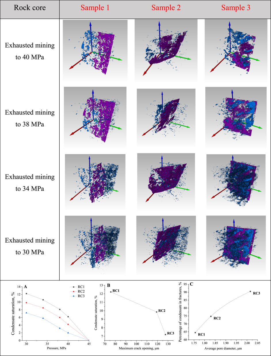
Figure 6. Variation of condensate distribution inside the cores under depletion mining mode, (A) condensate saturation in the three cores, (B) fracture opening versus condensate saturation, (C) pore diameter versus fracture condensate percentage.
In Sample 2, as pressure decreased, the saturation of condensate oil increased from 4.18% at 40 MPa to 9.86% at 30 Mpa. The fracture aperture of Rock Core 2 was nearly twice that of Rock Core 1, allowing condensate oil to almost completely fill the fracture surface at 30 MPa.
In Sample 3, as pressure decreased, the saturation of condensate oil increased from 2.03% at 40 MPa to 7.21% at 30 Mpa. The fracture aperture of Rock Core 3 was slightly larger than that of Rock Core 2, with condensate oil in the fractures forming a complete plane, filling most of the reservoir space with condensate oil. Rock Core 3 had the smallest average pore diameter, and only parts with large pore volumes and connectivity had permeability. Therefore, the condensate oil in the pores of Rock Core 3 was difficult to produce passively, resulting in a relatively high volume fraction of condensate oil in the pores.
In summary, in the three depletion experiments, when the pressure was reduced to 30 MPa, the average saturation of condensate oil inside the rock cores was around 10%, mainly located in fractures. There is a negative correlation between fracture aperture and condensate oil saturation, meaning that larger fracture apertures make it easier for condensate gas to carry away condensate oil, reducing the impact on exploitation efficiency. Yang et al. (2020) found in full-diameter rock core depletion tests that the gas recovery in rapid depletion tests was lower than in slow depletion tests. Conversely, without considering fluid flow in porous media, the condensate oil recovery in rapid depletion tests was higher than in slow depletion tests. This result is consistent with the conclusion of this study, indicating that a faster gas flow rate leads to a higher condensate oil recovery.
For low-saturation condensate gas reservoirs with original formation pressure higher than dew point pressure, pressure maintenance development is suitable. This development method first reduces pressure to near the dew point pressure by depressurization and then conducts cyclic gas injection to maintain pressure during production.
In the cycle gas injection experiment, the pressure was depleted from 45 MPa to 30 MPa and then restored to 45 MPa with dry gas for three cycles. In core sample one, after depletion, condensate oil mainly exists in fractures, predominantly distributed in layers. To characterize the distribution of condensate oil in the core, analysis was conducted at the intersection of fractures. The saturation of condensate oil in the core after depletion was 13.4%, and after three cycles of gas injection, it decreased to 9.8%, 8.6%, and 8.1% (Figure 7).
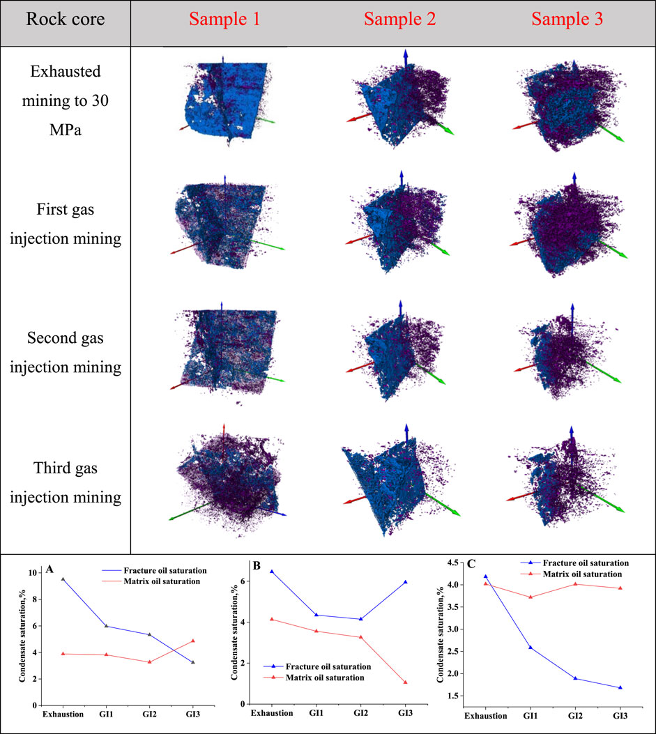
Figure 7. Variation of condensate distribution within the core under multiple cycles of gas injection mode, and the proportion of condensate distribution in the fractures and matrix [(A) Core I; (B) Core II; (C) Core III].
In core sample two, the saturation of condensate oil in the core after depletion was 10.6%, and after three cycles of gas injection, it decreased to 7.9%, 7.4%, and 7.0%. Core sample two has the largest pore diameter, resulting in the most effective utilization of condensate oil in the matrix. After depletion, condensate oil in the matrix accounted for 4.2% of the total porosity, decreasing to 1.1% after the third gas injection.
In core sample three, the saturation of condensate oil in the core after depletion was 8.2%, and after three cycles of gas injection, it decreased to 6.3%, 5.9%, and 5.6%. Core sample three has the largest fracture aperture, resulting in the most effective utilization of condensate oil in the fractures. After depletion, condensate oil in the fractures accounted for 4.2% of the total porosity, decreasing to 1.7% after the third gas injection.
In summary, in the three gas injection experiments, the average condensate oil saturation inside the core was 10% after the initial pressure reduction to 30 MPa, decreasing to 7% after three gas injections. In the condensate gas mixture system, the gas injection process will form a non-equilibrium “gas-gas” coexisting phase characteristic based on the difference in molecular potential energy. When the gas injection pressure approaches the dew point pressure, the injected dry gas will cause the remaining condensate gas system to exhibit a three-phase coexistence phenomenon of dry gas phase, condensate gas phase, and condensate oil phase. However, when the gas injection pressure is higher than the dew point pressure, the system shows a two-phase coexistence state of dry gas and condensate gas (Ganjdanesh et al., 2019; Tang et al., 2021). During the cyclic process, condensate oil in the fractures is first utilized and extracted, with the most significant effect observed during the first gas injection. As the three cycles of gas injection progress, the area of condensate oil in the fractures decreases. The above results are consistent with previous findings, indicating that gas injection can effectively evaporate and push condensate towards production wells, thereby increasing condensate recoveries (Long et al., 2024).
The order of fracture aperture size was Sample 1 < Sample 2 < Sample 3, and the order of pore diameter size was Sample 3 < Sample 1 < Sample 2. After utilizing condensate oil in the fractures, the condensate oil in the matrix was then utilized. Condensate oil in the fractures was more easily evaporated into associated gas and taken away during the production process compared to condensate oil in the pores. In the three cycles of gas injection in core sample three, the first cycle had the best effect, removing condensate oil from the fractures, while the second and third cycles had less impact on the condensate oil in the pores. The smaller the pore diameter, the more difficult it was for the injected associated gas to utilize the condensate oil within. This study aligned with Tang et al.’s (2021) results in multiple cyclic injection experiments in underground gas storage reservoirs of condensate gas fields, showing that condensate oil in some small-scale pores was challenging to utilize.
Two main methods of maintaining pressure during exploitation are full pressure maintenance and partial pressure maintenance. Full pressure maintenance involves keeping the pressure of the entire gas reservoir above the dew point pressure by matching gas production with gas injection until the condensate oil content and production reach their economic limits. Partial pressure maintenance, on the other hand, involves producing more gas than injecting when self-produced gas is insufficient to meet injection requirements. This method helps slow down pressure decline and reduce condensate oil losses.
In the cyclic gas injection experiment with different injection volumes, the pressure was first depleted to 30 MPa, then restored to 40, 45, and 48 MPa in three repetitions, representing fully and partially maintaining reservoir pressure development methods. The results showed that better utilization of condensate oil was achieved when the pressure was restored to higher levels. At pressure restoration to 40, 45, and 48 MPa, the cumulative recovery of condensate oil reached 21.4%, 31.6%, and 34.9% respectively (Figure 8). With increased injection volume, some liquid hydrocarbon components in the remaining condensate oil in the reservoir are extracted and evaporated into the injected gas, resulting in condensate volume contraction. Meng and Sheng (2016) optimized the parameters of gas injection through numerical simulations and found that gas injection was an effective method to increase the condensate oil recovery of shale gas reservoirs, with the optimal injection time being when the pressure in the main condensation area was raised above the dew point pressure.
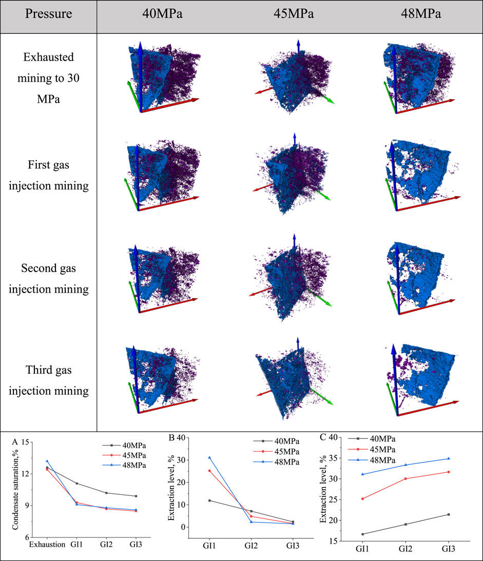
Figure 8. Variation of condensate distribution inside the core under multiple cycle gas injection modes with different injection volumes, (A) variation of condensate saturation inside the core; (B) degree of extraction in a single cycle; (C) degree of extraction in a cumulative cycle.
Under the same injection volume conditions, the effectiveness of condensate oil utilization decreased with each subsequent gas injection. Compared to the other two groups, the effect of the first gas injection was not significant when the gas was restored to 40 MPa. When the gas was restored to 48 MPa, after three gas injections, the best utilization of condensate oil in fractures and matrix was observed, with the saturation of condensate oil in fractures decreasing from 11.04% to 7.4% and in the matrix from 2.62% to 1.1%. As the injection volume increased, the oil production gradually decreased because the injected gas first extracted the light components from the condensate oil. As the injection volume increased, the extraction process became more difficult, leading to a gradual decrease in oil production. Additionally, with increasing injection volume, the cumulative increase in recovery also gradually increased. However, once the injection volume reached a certain value, the rate of cumulative recovery enhancement gradually slowed down.
In this study, during depletion exploitation when the pressure was reduced to 30 MPa, the average condensate saturation inside the core was 10%. Fractures served as the main flow channels, but there were oil film attachments on the walls. Segment plugs formed in fractures with small apertures, making it difficult to mobilise the condensate oil in the matrix. Upon switching to cyclic gas injection exploitation, the majority of the condensate oil in the fractures was effectively mobilised, while the mobilisation effect in the matrix was weaker. The most significant effect was observed during the first gas injection exploitation, with a decrease of around 3% in condensate saturation. In the second and third gas injection exploitations, the condensate saturation decreased by approximately 1% and 0.5% respectively (Figure 9). Cyclic gas injection extraction with full pressure retention ultimately recovered about 10% more of the internal condensate compared to partial pressure retention. These results indicate that compared to depletion exploitation, cyclic gas injection can significantly increase the condensate oil recovery, avoid the decrease of reservoir permeability caused by condensate oil accumulation, with fracture patterns, volume of injections, and injection recovery pressure being important factors influencing the condensate oil recovery.
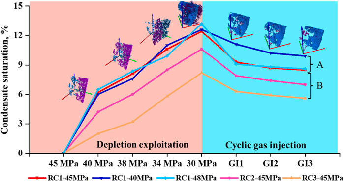
Figure 9. Variation of condensate saturation inside the core during depletion exploitation -cycle gas injection, A: variation of condensate saturation during multiple rounds of cycle gas injection with different injection volumes, B: variation of condensate saturation in different cores under the same cycle gas injection condition.
During the depletion process of condensate gas reservoirs, the decrease in pressure leads to phase change of condensate gas in the porous media, resulting in a reduction of residual condensate oil and thus lowering the recovery. Therefore, studying the dynamic behavior of condensate gas in porous media during different production processes provides an effective way for the seepage mechanism and development optimization of condensate oil and gas, which is of great significance for guiding production.
This study utilised real-time CT scanning technology to dynamically observe and analyse the morphology, occurrence, and characteristics of condensate liquid during depletion and cyclic gas injection processes. The research findings are as follows:
(1) The formation of oil films during the condensation process of condensate gas flowing through rock pores, exhibiting phenomena like “wave flow” and “segmented flow” closely adhering to the inner walls of the pores, is a result of intermolecular gravitational forces.
(2) In the depletion exploitation experiment, when the pressure is reduced to 30 Mpa, the condensate oil saturation in the core is around 10%, mainly present in the fractures. After depletion, with cyclic gas injection, the condensate oil saturation can decrease by over 30%, with the most significant effect seen in the first gas injection, where the passive condensate oil mainly comes from the fractures. After three cycles of gas injection, the saturation of the condensed oil decreased by approximately 3%, 1%, and 0.5% respectively.
(3) In the cyclic gas injection experiment, with pressure restored to 40, 45, and 48 MPa respectively, the cumulative recovery of condensate oil reached 21.4%, 31.6%, and 34.9%, indicating a positive relationship between gas injection volume and condensate oil recovery. However, once the injection volume exceeds the formation pressure, the increase in condensate oil recovery slows down.
(4) Comparing depletion exploitation and cyclic gas injection, cyclic gas injection significantly improves condensate oil recovery and reduces condensate oil damage to the reservoir. Factors such as fracture pattern, volume of gas injections, and recovery pressure are important factors influencing condensate oil recovery.
In future experimental and numerical simulation studies on condensate gas reservoirs, two key areas may require attention:
(1) Scale transformation: How to apply the condensate oil occurrence and flow laws obtained at the microscale to numerical simulations of gas reservoirs to guide the optimization of production schedule. The scale transformation issue is one of the unresolved challenges in oil and gas reservoir development.
(2) Many indoor experiments and mechanistic studies lag behind field practices. Therefore, it is essential to establish micro-scale numerical simulation methods. However, there are still many challenges in micro-scale numerical simulation work on fractured condensate gas reservoirs, such as how to realize the phase transition while flowing. The mass transfer laws between fractures and matrix under these conditions are not clear. Micro-scale numerical simulation of fractured condensate gas reservoirs is also a significant research direction.
The original contributions presented in the study are included in the article/supplementary material, further inquiries can be directed to the corresponding author.
LZ: Data curation, Writing–original draft. LJZ: Data curation, Formal Analysis, Writing–original draft. YS: Data curation, Project administration, Writing–review and editing. XT: Conceptualization, Project administration, Writing–original draft. CL: Methodology, Project administration, Writing–review and editing. SW: Resources, Validation, Writing–review and editing.
The author(s) declare that financial support was received for the research, authorship, and/or publication of this article.
Authors LZ, LJZ, YS, and XT were employed by CNOOC Research Institute Co., Ltd.
The remaining authors declare that the research was conducted in the absence of any commercial or financial relationships that could be construed as a potential conflict of interest.
All claims expressed in this article are solely those of the authors and do not necessarily represent those of their affiliated organizations, or those of the publisher, the editors and the reviewers. Any product that may be evaluated in this article, or claim that may be made by its manufacturer, is not guaranteed or endorsed by the publisher.
Abbasov, Z. Y., and Fataliyev, V. M. (2016). The effect of gas-condensate reservoir depletion stages on gas injection and the importance of the aerosol state of fluids in this process. J. Nat. Gas Sci. Eng. 31, 779–790. doi:10.1016/j.jngse.2016.03.079
Alarouj, M., Alomair, O., and Elsharkawy, A. (2020). Gas condensate reservoirs: characterization and calculation of dew-point pressure. Petroleum Explor. Dev. 47, 1091–1102. doi:10.1016/s1876-3804(20)60120-3
Dąbrowski, A. (2001). Adsorption — from theory to practice. Adv. Colloid Interface Sci. 93, 135–224. doi:10.1016/s0001-8686(00)00082-8
Dorhjie, D. B., Aminev, T., Mukhina, E., Gimazov, A., Babin, V., Khamidullin, D., et al. (2024). The underlying mechanisms that influence the flow of gas-condensates in porous medium: a review. Gas Sci. Eng. 122, 205204. doi:10.1016/j.jgsce.2023.205204
Faramarzi, N., and Sadeghnejad, S. (2020). Fluid and rock heterogeneity assessment of gas condensate reservoirs by wavelet transform of pressure-transient responses. J. Nat. Gas Sci. Eng. 81, 103469. doi:10.1016/j.jngse.2020.103469
Ganjdanesh, R., Yu, W., Fiallos, M. X., Kerr, E., Sepehrnoori, K., and Ambrose, R. (2019). “Gas injection EOR in eagle ford shale gas condensate reservoirs,” in SPE/AAPG/SEG Unconventional Resources Technology Conference, Denver, Colorado, 22–24 July 2019, 4744–4759.
Guo, P., Liu, H., Wang, C., DU, J., Fan, B., Jing, M., et al. (2020). The determination of phase behavior properties of high-temperature high-pressure and rich condensate gases. Fuel 280, 118568. doi:10.1016/j.fuel.2020.118568
Hosseinzadegan, A., Raoof, A., Mahdiyar, H., Nikooee, E., Ghaedi, M., and Qajar, J. (2023). Review on pore-network modeling studies of gas-condensate flow: pore structure, mechanisms, and implementations. Geoenergy Sci. Eng. 226, 211693. doi:10.1016/j.geoen.2023.211693
Hu, X., Pu, L., Ran, A., Xie, J., Li, F., Cheng, Y., et al. (2024). Micro formation mechanism of oil–water inversion in reservoirs based on water film theory—an example from the Dawangzhuang Oilfield in Bohai Bay Basin. Fuel 359, 130501. doi:10.1016/j.fuel.2023.130501
Jiang, T. (2023). Study on the supercritical phase behavior of Yaha condensate gas reservoir in Tarim Basin. Petroleum 9, 390–394. doi:10.1016/j.petlm.2021.11.007
Jing, W.-L., Zhang, L., Li, A.-F., Zhong, J.-J., Sun, H., Yang, Y.-F., et al. (2023). Phase behavior of gas condensate in porous media using real-time computed tomography scanning. Petroleum Sci. 21, 1032–1043. doi:10.1016/j.petsci.2023.11.009
Kumar, A., Gohary, M. E., Pedersen, K. S., and Azeem, J. (2015) “Gas injection as an enhanced recovery technique for gas condensates,” in A comparison of three injection gases. Abu dhabi international Petroleum Exhibition and conference.
Liu, X., Chen, H., Chen, Z., Yang, R., Song, L., Bai, M., et al. (2024). Study on characterization and distribution of four regions of tight sandstone condensate gas reservoirs in the depletion development process. Fuel 358, 130267. doi:10.1016/j.fuel.2023.130267
Long, K., Tang, Y., He, Y., Luo, Y., Hong, Y., Sun, Y., et al. (2024). Full-cycle enhancing condensate recovery-underground gas storage by integrating cyclic gas flooding and storage from gas condensate reservoirs. Energy 293, 130724. doi:10.1016/j.energy.2024.130724
Long, K., Tang, Y., He, Y., Wang, Y., Qin, J., and Tang, L. (2023). Fluid phase behavior during multi-cycle injection and production of underground gas storage based on gas-condensate reservoirs with oil rim. Geoenergy Sci. Eng. 226, 211769. doi:10.1016/j.geoen.2023.211769
Meng, X., and Sheng, J. J. (2016). Optimization of huff-n-puff gas injection in a shale gas condensate reservoir. J. Unconv. Oil Gas Resour. 16, 34–44. doi:10.1016/j.juogr.2016.09.003
Nabae, Y., Kawai, K., and Fukagata, K. (2020). Prediction of drag reduction effect by streamwise traveling wave-like wall deformation in turbulent channel flow at practically high Reynolds numbers. Int. J. Heat Fluid Flow 82, 108550. doi:10.1016/j.ijheatfluidflow.2020.108550
Nasriani, H. R., Borazjani, A. A., Iraji, B., and Moradidowlatabad, M. (2015). Investigation into the effect of capillary number on productivity of a lean gas condensate reservoir. J. Petroleum Sci. Eng. 135, 384–390. doi:10.1016/j.petrol.2015.09.030
Passoni, S., Ferrario, A., Ricotti, M. E., and Mereu, R. (2024). Experimental investigation of two-phase flow in Chevron-type compact plate heat exchangers: a Study on pressure drops and flow regimes visualization. Appl. Therm. Eng. 242, 122542. doi:10.1016/j.applthermaleng.2024.122542
Patmonoaji, A., Tsuji, K., and Suekane, T. (2020). Pore-throat characterization of unconsolidated porous media using watershed-segmentation algorithm. Powder Technol. 362, 635–644. doi:10.1016/j.powtec.2019.12.026
Reis, P. K. P., and Carvalho, M. S. (2022). Pore-scale analysis of gas injection in gas-condensate reservoirs. J. Petroleum Sci. Eng. 212, 110189. doi:10.1016/j.petrol.2022.110189
Salmani, N., Fatehi, R., and Azin, R. (2020). On the liquid condensate vertical migration near the production wells of gas-condensate reservoirs. Eng. Sci. Technol. Int. J. 23, 715–722. doi:10.1016/j.jestch.2020.03.006
Shi, J., Huang, L., Li, X., and Sepehrnoori, K. (2015). Production forecasting of gas condensate well considering fluid phase behavior in the reservoir and wellbore. J. Nat. Gas Sci. Eng. 24, 279–290. doi:10.1016/j.jngse.2015.03.033
Tang, Y., Long, K., Wang, J., Xu, H., Wang, Y., He, Y., et al. (2021). Change of phase state during multi-cycle injection and production process of condensate gas reservoir based underground gas storage. Petroleum Explor. Dev. 48, 395–406. doi:10.1016/s1876-3804(21)60031-9
Wang, H. S., Rose, J. W., and Honda, H. (2004). A theoretical model of film condensation in square section horizontal microchannels. Chem. Eng. Res. Des. 82, 430–434. doi:10.1205/026387604323050137
Wang, C., Yao, J., Huang, Z., Liu, F., and Yang, Y. (2024). Digital core reconstruction based on discrete element and Markov chain-Monte Carlo methods. Geoenergy Sci. Eng. 236, 212422. doi:10.1016/j.geoen.2023.212422
Wang, J., Luo, X., Xu, H., Jiang, H., and Nie, F. (2022). Phase behavior of condensate gas and CO2/CH4 re-injection performance on its retrograde condensation. Arabian J. Chem. 15, 104065. doi:10.1016/j.arabjc.2022.104065
Wang, Q. (2023). Origin of gas condensate reservoir in fuman oilfield, tarim basin, NW China. Petroleum Explor. Dev. 50, 1295–1307. doi:10.1016/s1876-3804(24)60467-2
Wang, S., Zuo, H., Gao, C.-N., Wang, J.-H., Congcong, L., and Wang, S. (2023). Characterization of differential markers among crude oil samples using UPLC-QE-MS/MS and multivariate statistical analysis. Energy & Fuels 37, 11017–11026. doi:10.1021/acs.energyfuels.3c02068
Yang, Y., Lun, Z., Wang, R., and Hu, W. (2020). Non-equilibrium phase behavior in gas condensate depletion experiments. Fluid Phase Equilibria 506, 112410. doi:10.1016/j.fluid.2019.112410
Keywords: in-situ CT, cyclic gas injection, phase behavior, fractured condensate gas reservoirs, depletion exploitation
Citation: Zhao L, Zhang L, Su Y, Tan X, Li C and Wang S (2024) In-situ CT study on the effect of cyclic gas injection and depletion exploitation on the phase behavior of fractured condensate gas reservoirs. Front. Earth Sci. 12:1418821. doi: 10.3389/feart.2024.1418821
Received: 17 April 2024; Accepted: 07 June 2024;
Published: 02 July 2024.
Edited by:
Yu Jing, University of New South Wales, AustraliaReviewed by:
Huazhou Li, University of Alberta, CanadaCopyright © 2024 Zhao, Zhang, Su, Tan, Li and Wang. This is an open-access article distributed under the terms of the Creative Commons Attribution License (CC BY). The use, distribution or reproduction in other forums is permitted, provided the original author(s) and the copyright owner(s) are credited and that the original publication in this journal is cited, in accordance with accepted academic practice. No use, distribution or reproduction is permitted which does not comply with these terms.
*Correspondence: Shuoliang Wang, d2FuZ3NodW9saWFuZ0BjdWdiLmVkdS5jbg==
Disclaimer: All claims expressed in this article are solely those of the authors and do not necessarily represent those of their affiliated organizations, or those of the publisher, the editors and the reviewers. Any product that may be evaluated in this article or claim that may be made by its manufacturer is not guaranteed or endorsed by the publisher.
Research integrity at Frontiers
Learn more about the work of our research integrity team to safeguard the quality of each article we publish.