 Lin Teng
 Menglong Dong
 Xiansen Xing2
 Zujian Liu
94% of researchers rate our articles as excellent or good
Learn more about the work of our research integrity team to safeguard the quality of each article we publish.
Find out more
ORIGINAL RESEARCH article
Front. Earth Sci., 19 June 2024
Sec. Geohazards and Georisks
Volume 12 - 2024 | https://doi.org/10.3389/feart.2024.1405573
This article is part of the Research TopicMechanism, Stability and Mitigation of Large-scale Reservoir LandslidesView all 8 articles
The toppling deformation in bank slope of V-shaped Gorge reservoirs in Southwest China is very common. After the impoundment of the reservoir, geological disasters such as collapse and landslide may occur in toppling bank slope, which poses a threat to the normal operation of hydropower projects and personnel safety. Therefore, it is of great engineering significance to study its genetic mechanism and development law. The trenching of river valley is one of the main factors of bank slope toppling deformation. In the process of river action, the free face is formed on the slope, and the rock mass is unloaded to the free face, resulting in toppling. Taking the bank slope of a reservoir in the V-shaped Gorge area on the edge of the Qinghai Tibet Plateau in Southwest China as an example, this paper studies the relationship between river action and the development of toppling. According to the seven terraces formed on both banks of the river, the trenching of the river valley is divided into seven stages. The toppling development characteristics of each stage are analyzed by discrete element method. According to the development characteristics of toppling deformation category, the toppling deformation is divided into five stages, they are initial toppling deformation stage, toppling development stage, intensified toppling deformation stage, temporary stability stage and failure stage. The research results can help to determine the development type and stage of bank slope toppling deformation in V-shaped Gorge area, so as to predict its further development deformation characteristics.
With the rapid development of technology and abundant water resources reserves, hydropower has gradually become an important power supply system in recent years. Hydropower is a new type of clean energy, but it needs to be reasonably developed and prevented from natural disasters. Due to the continuous uplift and strong regional tectonic activities of the Qinghai-Tibet Plateau in Southwest China, the region has formed a unique deep cutting high mountain canyon landform with deep valleys and steep bank slopes. The construction and operation of hydropower stations in this area are faced with complex and changeable engineering geological problems. The problem of bank slope toppling is particularly common and prominent.
Toppling is a typical instability form of anti-dip slope in V-shaped Gorge area. At present, the recognized toppling types are summarized by Goodman and Bray (1976). Different scholars have different views on the influencing factors of toppling (Wyllie, 1980; Pritchard and Savigny, 1990; Bobet, 1999; Mehdi et al., 2009; Zhao et al., 2016). Goodman and Bray (1976) classified the toppled deformed rock mass into four basic types, namely, bending toppling, block toppling, block bending toppling, and secondary toppling. Mehdi et al. (2009) found that the deformation of toppled rock masses occurs in various types of combinations. Pure bending toppling or pure block toppling is mainly based on theoretical research. Therefore, he proposed a composite mode of block bending toppling failure (Mehdi et al., 2009).
The research methods on influencing factors of toppling mainly include physical model test method and numerical simulation method.
At present, the commonly used physical model test methods include inclined test-bed test method, base friction test method, centrifuge test method and gravity method. Wong and Chiu (2001) developed a three-dimensional tilt test-bed, which can apply different pressures on the side of the model to simulate the gravity conditions of toppling deformation. Aydan and Kawamoto (1992) verified the method of residual toppling force to judge slope stability through base friction test. Chen (1995) developed a large base friction test-bed, which can better simulate flexural toppling. Li et al. (2019); Chena et al. (2020) used shaking table to study the relationship between discontinuity and toppling deformation, as well as the stability changes of anti-dip rock slope with joint development under the influence of external dynamic conditions. Alzoubi et al. (2010); Chen et al. (2015) used the centrifuge method to simulate the conditions of toppling deformation, and combined with the comparative numerical simulation method to study the relationship between the failure depth of toppling deformation and the sliding surface caused by slope deformation. Dong et al. (2020a); Dong et al. (2020b) used the self-weight of the test rock mass and jack load to considered the influence of the development position of the discontinuous structural plane and lithology on the toppling characteristics and laws. Zhu et al. (2020); Tao et al. (2021); Zhu et al. (2021) used physical modelling to study the toppling failure mechanism of anti-dip slope due to excavation.
Limit equilibrium method is the most common analysis method to study toppling slope stability at present. Goodman and Bray (1976) first proposed the toppling stability analysis method based on limit equilibrium theory (G-B method). Lu improved the cantilever beam bending limit equilibrium method proposed by Adhikary and Dyshin (Lu and Zhang, 2012; Li et al., 2019). In addition, many other methods have been used to predict landslide problems caused by toppling deformation in the reservoir area. Zhang et al. (2024) used an ensemble model of SVR to study the prediction of landslides in reservoir areas. Wang et al. (2013) studied the mechanism of landslide formation on the overlying mountain in the goaf of gently inclined coal seams. Zhao et al. (2016) studied the geomechanical model of the formation of gentle anti-dip mining induced landslides.
Because the slope toppling is mainly characterized by the bending and breaking failure of inclined rock columns, the stress-strain analysis method based on discontinuous medium model is a more effective method to analyze the toppling failure of rock slope. In this paper, discrete element method (DEM) developed by Cundall and Hart (1992); Cundall (1998); Itasca (2009) company are used to numerical simulate for discontinuous media.
The existing research results do not have a comprehensive impact on the relationship between the development of toppling deformation of V-shaped canyon reservoir bank slopes and river downcutting. A hydropower station is located on the eastern edge of the Qinghai Tibet Plateau in the west of Yunnan Province, China. The regional tectonic environment is complex. Due to the erosion of the river on the surface for many years, a deep cut V-shaped Gorge landform is formed. The slope lithology of the reservoir area is mainly composed of Jurassic phyllitic sericite slate, metamorphic quartz sandstone, purplish red mudstone and silty mudstone. Frequent tectonic activities in the reservoir area leads to steep bank slope, steep rock stratum, joint fissure development and poor rock mass integrity, which provides good conditions for the development of bank slope toppling. Under special circumstances, the toppling deformation body has the possibility of instability and failure. Once it is unstable, it will affect the normal operation of the hydropower station, increase the project maintenance cost and cause major economic losses.
A thorough analysis of the river’s impact on the formation of toppling deformation bodies offers a sound foundation for the mitigation of toppling and the reduction of disaster risks. The aim of this paper is to explore the influence of river action on the genesis and evolution of toppling, as well as to identify the current stage and future trends of toppling in reservoir bank slopes. This research provides a scientific rationale for ensuring the safe operation and disaster prevention of the reservoir.
Since the Quaternary, the research area affected by the Qinghai Tibet Plateau. The uplift and denudation of the western Yunnan Plateau had been strong, and the uplift of the paleo planation plane reflected the uplift of the earth’s crust. In the canyon area of the reservoir, the elevation of Pliocene planation level is 2,500–2,600 m, the current elevation of ancient planation level is 3,200–3,300 m, and the uplift height of Quaternary is 600–800 m. The elevation of the river valley bottom in this reach is about 1,368 m, and the great height difference means that the depth of the valley undercut is more than 1,000 m. Before the valley was trenched, the cumulative value of in-situ stress was high. When it was trenched to the current valley bottom, the unloading of rock mass was also relatively large. The geological conditions made the river curved, the valley deep, the gullies on both banks developed and the terrain steep, resulting in forming a unique landform of high mountains and deep canyons.
The main topographic conditions of toppling include the followings. The first condition is the river form. At the bend of the valley, the river carries a large amount of sediment, which erodes the rock mass at the foot of the slope under the scouring action of high-speed water flow. The water carries the eroded rock blocks to the downstream sedimentation. Under the long-term scouring action, the slope toe is unstable and the upper rock mass continues to topple. The second condition is the development conditions of gullies. If the gullies are developed on one side or both sides of the slope, the stress is released to the side of the gullies, which provides unique free conditions for toppling deformation. The last condition is the slope shape. The bank slope angle is greater than 40°, the ridge in the middle of the slope is prominent, and the vegetation coverage is low.
Under the action of river trenching and denudation, the deep rock mass rises to the shallow, and the ratio of horizontal stress to vertical stress increases continuously. Before denudation, there is a certain amount of in-situ stress in the rock mass. After denudation, the stress release in the rock mass cannot catch up with denudation, resulting in a much larger stress caused by denudation existing in the slope.
The study area of a hydropower station formed the main formation lithology from Late Triassic to Cretaceous. It includes phyllitic sericite slate, fine sandstone, metamorphic quartz sandstone and slate. Among them, metamorphic quartz sandstone and slate rock mass are hard and belong to brittle rock mass, which will produce interlayer tension cracks under geological action, and then fracture along the cracks, release internal energy and intensify the process of toppling. Such rock mass will form block toppling. Phyllite and phyllitic slate are relatively weak and belong to soft rock. They are prone to bending and wrinkling under geological action. Such rock mass forms flexural toppling.
A series of fold belts were formed in the tectonic movement, which provided material conditions for the formation of toppling.
The evolution of valley landform is divided into peneplain period, wide valley period and canyon period. The location of planation surface reflects peneplain period and wide valley period, and river terrace reflects canyon period. Seven river terraces were developed in the Tu’e reach of Lancang River Basin in the study area. Paleogeothermal method and mass balance method were used to measure the river terrace, and the uplift rate and denudation rate of the seventh terrace of Tu’e section Lancang River are obtained, shown as Table 1.
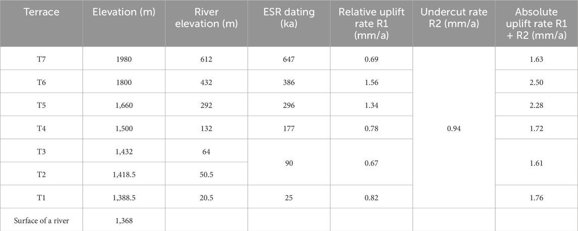
Table 1. Terrace uplift rate of Lancang River.
The terraces of Tu’e reach of Lancang River are shown in Figure 1. During the formation of terrace, the valley was cut down by 612 m, it forms a V-shaped gorge.
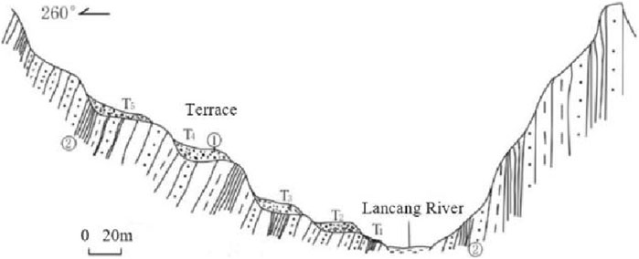
Figure 1. River terrace profile of Lancang River. ①Gravel layer; ②Sandstone slate interbedding.
Taking a toppling slope of Miaowei Hydropower Station as an example, stress concentration occurred at the intersection of steep and gentle terrain in the middle of the slope. In order to further understand the stress distribution pattern in this area in detail, a longitudinal section with X=200 m was selected to plot the maximum principal stress
Research on stress distribution in river valleys has already been conducted in the early stage. From Figure 2A, it can be seen that the overall trend of the maximum principal stress changing with depth is first increasing, then decreasing, and finally stabilizing. The maximum value of the maximum principal stress is 3.0 MPa. The stress values are roughly distributed in three intervals: the 0–40 m stress reduction zone, the 40–80 m stress rise zone, and the 80–120 m original stress zone.
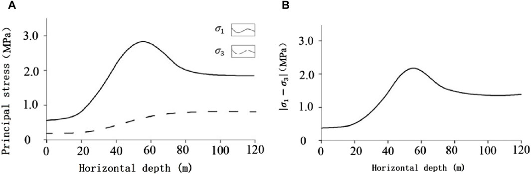
Figure 2. Principal stress (A) Variation of principal stress with horizontal depth; (B) Diagram of stress
Based on the above analysis, draw a stress diagram for the hump of the toppling slope, as shown in Figure 2B. As the valley is cut down, the internal stress of the slope redistributes, and the maximum principal stress gradually develops towards the direction perpendicular to the river. At the same time, the internal stress of the slope gradually decreases. Under the action of tensile stress, tensile cracks gradually appear at the rear edge of the slope, and a gently inclined structural plane is formed in the slope body. Due to the free surface of the slope, it is beneficial for the development and extension of tensile cracks and gently inclined structural planes. Under the action of weathering and water flow, it promotes the relaxation deformation and stress release of the rock mass, leading to the continuous development of slope tilting deformation.
In order to study the relationship between river action and toppling, the state of toppling during the formation period of each terrace was simulated according to the river terrace information of Lancang River Tu’e reach. Numerical simulation is conducted using the two-dimensional discrete element software UDEC from Itasca company.
The Lancang River bank slope has been selected to establish the discrete element geological model. The bottom elevation of the model is 1,116 m, the top elevation is 1,916 m, the height of the model is 800 m, and the length of the model is 1,300 m.
The bottom of the model is constrained by the displacement in the vertical direction, the left and right boundaries are constrained by the displacement in the horizontal direction, and the model is only affected by gravity. The rock mass is endowed with Mohr Coulomb attribute, and the structural plane is endowed with Coulomb slip model.
According to the historical evolution of the river valley, the topographic line of the toppling slope was inferred, and then the elevation of seven grade river valleys were determined from the information in Table 1. When the seven terraces were formed, the cutting depth of the valley was 180 m. Thus, the variation characteristics of toppling in the process of river trenching were simulated. By using the two-dimensional discrete element method software UDEC for analysis. The model shown as Figure 3.
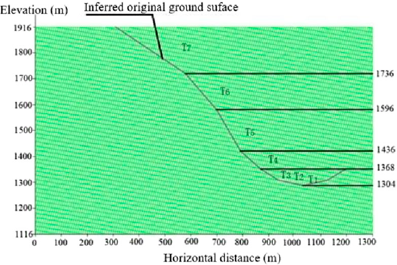
Figure 3. The model of river action.
The parameters of rock mass and discontinuity surface required for simulation were obtained according to the physical test in the study area (combination of indoor test and field test) and relevant engineering geological analogy analysis method.
During the formation of the seventh terrace, the river valley was trenched to the elevation of 1,736 m. Due to the limitation of free surface conditions, the space of rock mass deformation was limited. In the shallow part of the slope, the deformation was mainly unloading rebound deformation. Interlayers were characterized by interlaminar dislocation and compression deformation. The maximum displacement in the X direction was about 1.6 m, and there was no obvious toppling deformation feature in this terrace, shown in Figures 4A, B.
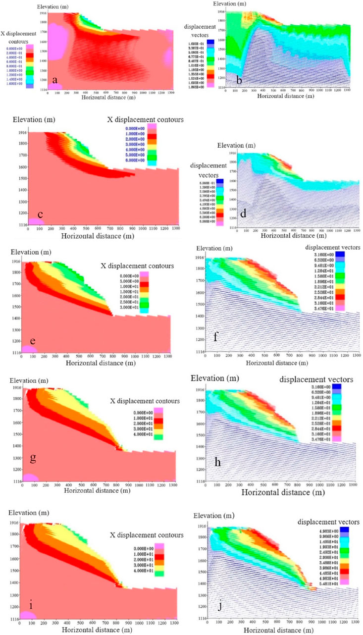
Figure 4. Displacement nephogram and Velocity vector diagram (A) Displacement nephogram in X direction of T7 stage; (B) Velocity vector diagram of T7 stage; (C) Displacement nephogram in X direction of T6 stage; (D) Velocity vector diagram of T6 stage; (E) Displacement nephogram in X direction of T5 stage; (F) Velocity vector diagram of T5 stage; (G) Displacement nephogram in X direction of T4 stage; (H) Velocity vector diagram of T4 stage; (I) Displacement nephogram in X direction of T3, T2 and T1 stage; (J) Figure12 Velocity vector diagram of T3, T2 and T1 stage.
During the formation of the sixth terrace, the valley was trenched to an elevation of 1,596 m. The rock mass had a slow toppling to the free surface, so the unloading deformation occurred at the shallow surface and valley bottom of the slope. The rock block at the top of the slope occurred shear and slide deformation. The maximum displacement in the X direction was about 6 m, shown in Figures 4C, D.
During the formation period of the fifth terrace, the valley was trenched to an elevation of 1,436 m. The back edge of the slope body occurred tension deformation, the tension crack had been grown. The rock mass at the foot of the slope occurred shear slip. The maximum displacement in X direction was about 30 m, shown in Figures 4E, F.
During the formation of the fourth terrace, the valley was trenched to an elevation of 1,368 m. The unloading rebound deformation was intensified, and tensile cracks occurred at the trailing edge of the slope. Under the pressure of the overlying rock mass, the slope toe had obvious toppling and shear slip. The maximum displacement in X direction was about 40 m, shown in Figures 4G, H.
During the formation period of the first to third terraces, the valley was trenched to the elevation of 1,304 m. The deep canyon landform was officially formed, and the horizontal depth of deformation was about 200 m. The trailing edge of the slope was cracked, and the slope toe was sheared. The maximum displacement in X direction was about 58 m, shown in Figures 4I, J.
The relationship between the age of river action and displacement is shown in Figure 5A. With the continuous trenching of the valley and the formation of the river terrace, the slope displacement of the toppling deformed continues to increase, and the cumulative displacement of the slope is about 60 m.
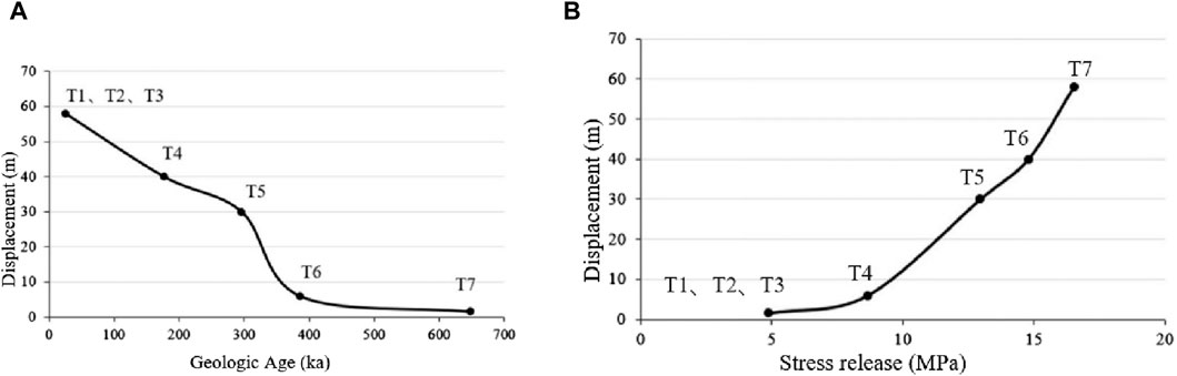
Figure 5. (A) Relationship between geological age and displacement of river action; (B) Relationship between stress release and displacement caused by river action.
The relationship between shear stress and displacement of river valley is shown in Figure 5B. With the increase of stress release, the displacement of toppling increases continuously, and the maximum stress release is about 17 MPa.
According to the analysis of the deformation characteristics, rock mass structure and deformation failure mode of the toppling in the study area, the deformation development process of the toppling was numerically simulated and analyzed by using UDEC software (based on the discrete element method). The genetic mechanism of the toppling was studied at the same time.
A toppling slope of a hydropower station in Lancang river was selected as research background of this paper, and the discrete element calculation model of toppling slope was established (Figure 6A). According to the on-site investigation of the bank slope, a group of rock layer and joint outside the gently inclined slope were set in the model. The physical and mechanical parameters of rock mass were obtained by rock mass mechanical tests on samples of different rock strata and ore bodies. Uniaxial compression test, shear test and tensile test were adopted. Parameters of rock mass and structural plane are shown in Tables 2, 3.
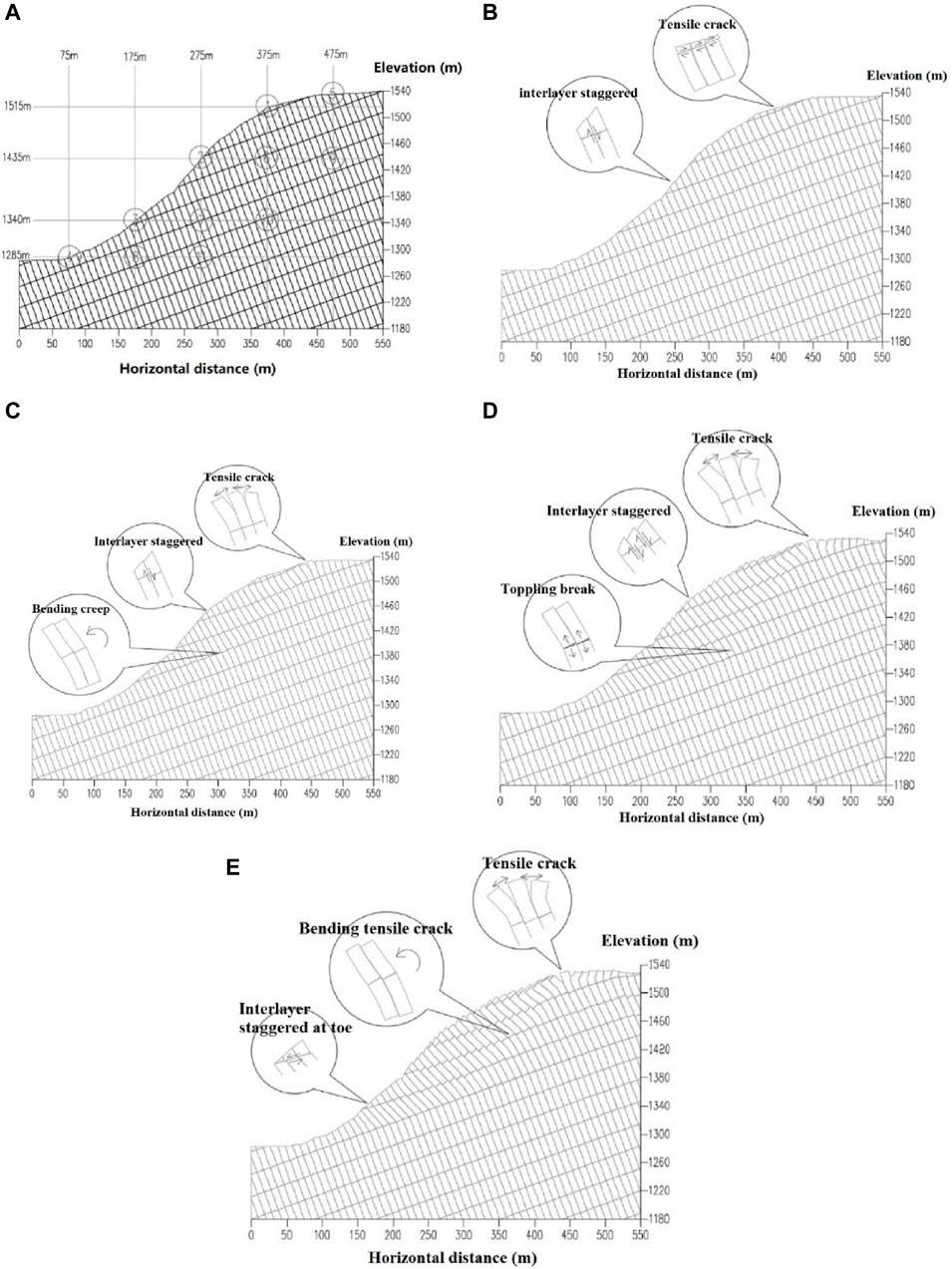
Figure 6. (A) Discrete element model of toppling slope; (B) Toppling development stage; (C) Intensified toppling deformation stage; (D) Temporary stability stage; (E) Failure stage.

Table 2. Mechanical parameters of slope rock mass.
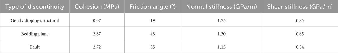
Table 3. Mechanical parameters of discontinuity.
According to the numerical simulation of toppling slope, the development process of toppling deformation is divided into five stages.
Under the action of unloading and the self-weight of rock mass, the tensile cracks will occur on the slope top along the gently inclined structural plane. The distance of tension crack is small, and the tension crack between rock layers is not obvious. Due to the cohesion of the structural plane, interlayer dislocation will occur in the middle of the slope, and the dislocation distance is slight.
Under the continuous action of gravity, the trailing edge rock strata are obviously pulled apart and opened to form reverse steps. Interlaminar dislocation increases gradually, and bending creep deformation will occur in the rock stratum inside the slope. With the increase of calculation time step, the rock creep becomes more and more obvious, the slope toe has slight sliding deformation, and the tensile cracks of the slope body from the inside to the shallow surface are increasing. The deformation of rock mass at this stage is mainly tensile crack and creep. Shown as Figure 6B.
With the aggravation of the bending creep of rock stratum, when the moment acting on the rock mass is greater than the tensile strength, the stress concentration will occur at the root of the slope. The rock stratum will break at the position of tensile stress concentration. The tensile crack at the back edge of the slope continues to expand, and the interlaminar displacement increases obviously. The deformation of rock mass is mainly tensile cracking, bending, toppling and fracturing. Shown as Figure 6C.
At this stage, the tensile crack at the trailing edge of the slope will not increase further, and there is only slight dislocation at the slope toe. The root of the rock mass is bent and broken, but the fracture section is not continuously connected in the slope. With the increase of calculation time step, the displacement of slope will not change significantly. Shown as Figure 6D.
In the long-term geological history, due to the disturbance of internal and external dynamic geological conditions, the slope will enter the failure stage from the temporary stability stage. The instantaneous damage caused by seismic dynamic action makes the slope break quickly, the formed fracture section runs through, and the toppling slope deforms rapidly. Reservoir storage, long-term rainfall and rock weathering reduce the mechanical strength of rock mass and soften the structural plane. When a certain critical value is reached, the slope will be damaged. Due to the excavation of slope toe and other factors, the slope toe loses its support, and the fracture of rock mass increases sharply, forming a continuous through fracture section, causing damage to the free surface. Shown as Figure 6E.
The rear part of the toppling slope is mainly vertical displacement, and the front edge of the slope is deformed in the free direction. The displacement field of slope body changes differently. The shallow surface of the whole slope has a large free face, with obvious toppling deformation. The displacement in the middle decreases, mainly due to bending and toppling deformation. The lower displacement changes little.
The displacement in the middle of the slope is relatively small, which is a weak toppling area of the slope. The toppling in the deep of the slope is weak, the deformation is not obvious. It is the non-toppling area. Shown as Figure 7.
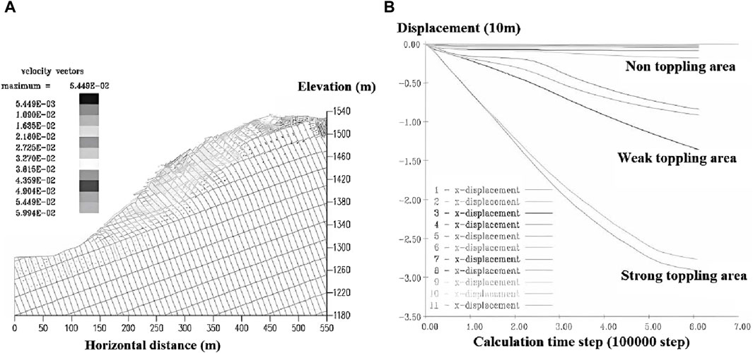
Figure 7. Model displacement and monitoring data (A) Velocity vector diagram of toppling; (B) Displacement curve of monitoring points.
This paper delves into the geological reasons behind bank slope toppling, taking into account factors such as river action, lithological formations, landforms, and more. Over the long-term geological evolution, multi-stage tectonic movements shaped and transformed the rock mass, resulting in a distinctive V-shaped Gorge terrain. Within the study area, Jurassic and Cretaceous slate, phyllite, phyllitic slate, and metamorphic quartz sandstone are present, creating a thin-layered and interbedded rock mass structure along with an anti-dip slope. These geological features, coupled with the long-term erosion of the river valley, continuously adjust the in-situ stress, leading to a strong unloading effect on the slope. This unloading effect provides favorable conditions for slope deformation and subsequent toppling. Furthermore, the prolonged erosion of the valley, the constant realignment of in-situ stress, and the intense unloading effect of the slope altogether contribute to optimal deformation conditions for bank slope toppling.
According to the seven terraces formed on both banks of the river, the trenching of the river valley is divided into seven stages. And according to the development characteristics of toppling deformation category, the toppling deformation is divided into five stages, they are initial toppling deformation stage, toppling development stage, intensified toppling deformation stage, temporary stability stage and failure stage. The research results can help to determine the development type and stage of bank slope toppling deformation in V-shaped Gorge area. After determining the stage of toppling development, we can understand the characteristics and deformation trends of toppling development. Based on this analysis result, we can help determine targeted measures for the support treatment of toppling deformed rock slope.
The datasets presented in this study can be found in online repositories. The names of the repository/repositories and accession number(s) can be found in the article/Supplementary Material.
LT: Conceptualization, Writing–original draft. MD: Conceptualization, Writing–original draft, Writing–review and editing. XX: Investigation, Writing–original draft. YX: Conceptualization, Writing–review and editing. CS: Conceptualization, Writing–original draft. ZL: Conceptualization, Writing–original draft. KY: Conceptualization, Writing–original draft.
The author(s) declare that financial support was received for the research, authorship, and/or publication of this article. This study is supported by the Open Research Fund of Key Laboratory of Construction and Safety of Water Engineering of the Ministry of Water Resources, China Institute of Water Resources and Hydropower Research (Grant No. IWHR-ENGI-202302), the Research Fund of National Natural Science Foundation of Shandong Province of China (NSFC) (Grant No. ZR2022ME188), Jinan City “new university 20” research leader studio project (Grant No. 20228108), and the project of Slope safety control and disaster prevention technology innovation team of “Youth Innovation Talent Introduction and Education Plan” of Shandong Colleges and universities [Grant No. Lu Jiao Ke Han (2021) No. 51].
Author KY was employed by Xinjiang Jinman Architecture and Landscape Engineering Co., Ltd.
The remaining authors declare that the research was conducted in the absence of any commercial or financial relationships that could be construed as a potential conflict of interest.
All claims expressed in this article are solely those of the authors and do not necessarily represent those of their affiliated organizations, or those of the publisher, the editors and the reviewers. Any product that may be evaluated in this article, or claim that may be made by its manufacturer, is not guaranteed or endorsed by the publisher.
Alzoubi, A., Martin, C., and Cruden, D. (2010). Influence of tensile strength on toppling failure in centrifuge tests. Int. J. Rock Mech. Min. Sci. 47, 974–982. doi:10.1016/j.ijrmms.2010.05.011
Aydan, O., and Kawamoto, T. (1992). The stability of slopes and underground openings against flexural toppling and their stabilisation. Rock Mech. Rock Eng. 25 (3), 143–165. doi:10.1007/BF01019709
Bobet, A. (1999). Analytical solutions for toppling failure. Int. J. Rock Mech. Min. Sci. 36, 971–980. doi:10.1016/S0148-9062(99)00059-5
Chen, Z. Y. (1995). “Recent developments in slope stability analysis,” in Proceedings of the 8th international congress on rock mechanics (september 25-30, 1995, tokyo) (Keynote Lecture), 3, 1041–1048.
Chen, Z. Y., Gong, W. J., Ma, G. W., Wang, J., He, L., Xing, Y., et al. (2015). Comparisons between centrifuge and numerical modeling results for slope toppling failure. Sci. China Technol. Sci. 58 (9), 1497–1508. doi:10.1007/s11431-015-5889-x
Chena, C. C., Lia, H. H., Chiub, Y. C., and Tsaia, Y. K. (2020). Dynamic response of a physical anti-dip rock slope model revealed by shaking table tests. Eng. Geol. 277, 105772–105813. doi:10.1016/j.enggeo.2020.105772
Cundall, P. A. (1998). Formulation of a three-dimensional distinct element model—Part I. A scheme to detect and represent contacts in a system composed of many polyhedral blocks. Int. J. Rock Mech. Min. Sci. Geomechanics Abstr. 25, 107–116. doi:10.1016/0148-9062(88)92293-0
Cundall, P. A., and Hart, R. D. (1992). Numerical modelling of discontinua. Eng. Comput. 9, 101–113. doi:10.1108/eb023851
Dong, M. L., Zhang, F. M., Hu, M. J., and Liu, C. (2020b). Study on the influence of anchorage angle on the anchorage effect of soft-hard interbedded toppling deformed rock mass. KSCE J. Of Civ. Eng. 24, 2382–2392. doi:10.1007/s12205-020-2386-y
Dong, M. L., Zhang, F. M., Lv, J. Q., Fei, Y., and Li, Z. N. (2020a). Study of stability influencing factors of excavated anti-dip rock slope. KSCE J. Of Civ. Eng. 24, 2293–2303. doi:10.1007/s12205-020-1412-4
Goodman, R. E., and Bray, J. W. (1976). “Toppling of rock slopes,” in Rock engineering: American society of civil engineers, geotechnical engineering division conference (Boulder: Co. USA), 201–234.
Itasca (2009). 3DEC Three dimensional distinct element code user’s guide. Itasca Consulting Group Inc.
Li, L. Q., Ju, N. P., Zhang, S., and Deng, X. X. (2019). Shaking table test to assess seismic response differences between steep bedding and toppling rock slopes. Bull. Eng. Geol. Environ. 78, 519–531. doi:10.1007/s10064-017-1186-1
Lu, A. Z., and Zhang, N. (2012). Analytical method of calculating slope stability by elasticity theory and limit equilibrium method. Appl. Mech. Mater. 170-173, 1167–1173. doi:10.4028/scientific.net/AMM.170-173.1167
Mehdi, A., Abbas, M., and Omer, A. (2009). Stability analysis and the stabilisation of flexural toppling failure. Rock Mech. Rock Eng. 42 (5), 751–782. doi:10.1007/s00603-008-0020-2
Pritchard, M. A., and Savigny, K. W. (1990). Numerical modelling of toppling. Can. Geotechnical J. 27 (27), 823–834. doi:10.1139/t90-095
Tao, Z. G., Zhu, C., He, M. C., and Karakus, M. (2021). A physical modeling-based study on the control mechanisms of Negative Poisson's ratio anchor cable on the stratified toppling deformation of anti-inclined slopes. Int. J. Rock Mech. Min. Sci. 138, 104632. doi:10.1016/j.ijrmms.2021.104632
Wang, Y. C., Ju, N. P., Zhao, J. J., and Xiang, X. Q. (2013). Formation mechanism of landslide above the mined out area in gentle inclined coal beds. J. Eng. Geol. 21 (1), 61–68. doi:10.3969/j.issn.1004-9665.2013.01.007
Wong, R. H. C., and Chiu, M. A. (2001). “Study on failure mechanism of toppling by physical model testing,” in Proceedings of 38th U. S. Rock mechanics symposium, 989–995.
Wyllie, D. C. (1980). Toppling rock slope failures examples of analysis and stabilization. Rock Mech. 13 (2), 89–98. doi:10.1007/BF01238952
Zhang, J., Lin, C., Tang, H., Wen, T., Tannant, D. D., and Zhang, B. (2024). Input-parameter optimization using a SVR based ensemble model to predict landslide displacements in a reservoir area-A comparative study. Appl. Soft Comput. 150, 111107–111107.18. doi:10.1016/j.asoc.2023.111107
Zhao, J. J., Ma, Y. T., Lin, B., Lan, Z. Y., and Shi, W. B. (2016). Geomechanical mode of mining landslides with gently counter-inclined bedding─a case study of Madaling landslide in Guizhou Province. Chin. J. Rock Mech. Eng. 35 (11), 2217–2224. doi:10.13722/j.cnki.jrme.2016.0106
Zhu, C., He, M. C., Karakus, M., Cui, X. B., and Tao, Z. G. (2020). Investigating toppling failure mechanism of anti-dip layered slope due to excavation by physical modelling. Rock Mech. Rock Eng. 53 (11), 5029–5050. doi:10.1007/s00603-020-02207-y
Keywords: river action, bank slope, toppling deformation, discrete element method, V-shaped gorge reservoir
Citation: Teng L, Dong M, Xing X, Xu Y, Sun C, Liu Z and Yang K (2024) Research on the geological process of river action on the toppling deformation of rocky bank slopes in V-shaped gorge reservoirs. Front. Earth Sci. 12:1405573. doi: 10.3389/feart.2024.1405573
Received: 23 March 2024; Accepted: 09 May 2024;
Published: 19 June 2024.
Edited by:
Chenyang Zhang, Hong Kong Polytechnic University, Hong Kong SAR, ChinaReviewed by:
Yuting Yang, China University of Geosciences Wuhan, ChinaCopyright © 2024 Teng, Dong, Xing, Xu, Sun, Liu and Yang. This is an open-access article distributed under the terms of the Creative Commons Attribution License (CC BY). The use, distribution or reproduction in other forums is permitted, provided the original author(s) and the copyright owner(s) are credited and that the original publication in this journal is cited, in accordance with accepted academic practice. No use, distribution or reproduction is permitted which does not comply with these terms.
*Correspondence: Lin Teng, dGVuZ2xpbjEyMDhAMTYzLmNvbQ==
Disclaimer: All claims expressed in this article are solely those of the authors and do not necessarily represent those of their affiliated organizations, or those of the publisher, the editors and the reviewers. Any product that may be evaluated in this article or claim that may be made by its manufacturer is not guaranteed or endorsed by the publisher.
Research integrity at Frontiers
Learn more about the work of our research integrity team to safeguard the quality of each article we publish.