 Hongtao Dai
 Yang Sun
 Yao Rong1
 Junping Yu
 Jiangpeng Wu
 Yongjun Zhang
- 1Jiangxi Transportation Institute Co., Ltd., Nanchang, Jiangxi, China
- 2School of Civil Engineering, Qingdao University of Technology, Qingdao, Shandong, China
Soil pressure in clay formation tunnels is closely related to soil arch effect and the development of slip surfaces. Firstly, numerical simulation software is used to simulate the actual situation of tunnel excavation, and the change rule of the slip-cracking surface of cohesive soil is analyzed. Secondly, based on the numerical simulation results and the ellipsoid theory, the pressure formula of Terzaghi loose Earth is modified considering that the principal stress trace is catenary. Finally, the calculation results are compared with the finite element calculation results to verify the rationality of the formula in this paper. The relationship between the internal friction angle, cohesion force c, eccentricity ε, looseness coefficient β, and the pressure of loose Earth is further studied. The results show that there is a gap between the sliding crack angles with or without dilatancy angle and it will affect the development form of soil arch. The slip angle decreases gradually with the increase of the buried depth ratio H/D and becomes stable when the buried depth ratio H/D≥3. Compared with deep-buried tunnels, the increase of internal friction angle in the shallow-buried tunnel is more conducive to reducing the overlying soil pressure. The loose soil pressure decreases with the increase of eccentricity ε and loose coefficient β, and the influence of eccentricity ε on loose soil pressure is significantly greater than that of loose coefficient β. Therefore, the change of eccentricity ε should be paid close attention in the project.
1 Introduction
The soil arch effect is widespread in geotechnical engineering. In the process of tunnel excavation, due to the stress characteristics of the surrounding rock itself, the phenomenon of stress redistribution will occur (Chen et al., 2022). When the stress of the surrounding rock is greater than its bearing capacity, it will fail and gradually expand to the interior until the new stress balance is reached. At this time, the surrounding rock will form a certain loosening range, which is called the loosening zone (Geng et al., 2023). Due to the friction and bonding between soil particles, the interaction between particles will cause uneven deformation of surrounding rock in the loose zone (CHEN et al., 2011; Berthoz et al., 2018), and the stress of soil will be transferred to the surrounding rocks, resulting in the soil arching effect (Cao et al., 2020). For this reason, many scholars have carried out research on the loose Earth pressure of tunnels under the soil arch effect. Terzaghi (1943) derived the calculation formula of loose Earth pressure acting on the trapdoor by using the limit equilibrium theory through the trapdoor test and confirmed the existence of the soil arch effect above the tunnel.
After that, many scholars carried out more abundant research on the soil arch effect. Chen et al. (2008) analyzed the influence of pile-soil relative displacement on the stress concentration ratio of embankment through multiple trapdoor model tests. Rui et al. (2018) have conducted a series of two-dimensional model tests with a trapdoor test device, observed three soil arch evolution modes of triangular expansion, tower evolution, and equal settlement, proposed three analytical models to describe the evolution process of the three soil arch evolution modes, and deduced the analytic solution of the Earth pressure for the three evolution processes. The results are in good agreement with the model tests. Xu et al. (2018) analyzed three different principal stress trajectories, such as parabola, arc, and catenary, and considered the influence of large principal stress distribution in the loose area above the tunnel on the loose Earth pressure, and modified the formula of Terzaghi’s loose Earth pressure. Zou et al. (2019) modified the three-dimensional rotational failure model based on the limit analysis method and the wedge prism model based on the limit equilibrium method to modify the overburden pressure of the tunnel. Shukla and Sivakugan (2009) assumed that the slip plane was a curve and a sloping straight line respectively, and derived the formula for calculating the vertical stress between the sloping slip planes. Lee et al. (2004) conducted a series of centrifugal model tests on tunneling to study the tunnel failure mechanism of sand buried under the water table, and the proposed mechanism can accurately predict the vertical Earth pressure acting on the top of the sand tunnel, providing theoretical support for the tunnel lining design. Costa et al. (2009) conducted a centrifugal model test based on the trapdoor device, studied the soil failure modes above the trapdoor under different burial depths and gravity fields, and compared the differences between the two. In the theoretical study of overlying Earth pressure in deep buried tunnels, there are various forms of sliding surfaces, including triangles, parallelograms, parabolas, and so on. As a relatively mature theory, the ellipsoid theory can better describe the actual conditions of tunnel top pressure change and formation deformation. For example, for the soil with fine particles, the interparticle force is larger, the top pressure is larger, and the tunnel is easy to settle, and the ellipsoid theory can better explain this phenomenon. Based on the particle ellipsoid theory, Gong et al. (2017) deduced the coefficient of lateral Earth pressure affected by the inclination of the slip plane and the calculation method of tunnel loose Earth pressure. Wu et al. (2019) determined the shape and size of the loose area according to the principle of gravity flow, assumed that the Earth pressure in the loose area was not uniformly distributed, and modified the formula of Terzaghi’s loose Earth pressure. Chevalier et al. (2012) established a trapdoor test device under plane strain and conducted tests on a variety of geotechnical materials. Based on the tests, discrete elements were used to model the trapdoor problem, and the load-displacement curve was divided into three critical stages. Adachi et al. (2003) studied the evolution law of the soil arch effect during tunnel excavation through a three-dimensional trapdoor test, measured the overlying soil pressure and surface settlement of the tunnel, and observed another soil pressure within the loose area. Xu et al. (2019) carried out a model experimental study on the soil arch effect under seepage conditions. Liang et al. (2020) analyzed the evolution process of soil arch in detail from the experimental and theoretical perspectives and obtained the calculation formula of the evolution process of overlying soil pressure on the tunnel. Handy (1985) derived the expression of the lateral Earth pressure coefficient from the angle of principal stress deflection and assumed that the arch trace was catenary.
In the past, scholars have carried out detailed research on the dynamic Earth pressure above the tunnel and obtained many instructive results. However, there is little research on the soil arch effect in the case of clay formation, and the variation of overlying soil pressure has not been further studied. Therefore, numerical simulation software is used to calculate the overlying soil pressure after tunnel excavation, and the evolution law of the soil arch effect under cohesive soil is analyzed. Secondly, based on the fracture surface of the tunnel arch and the ellipsoid theory, the pressure of Terzaghi loose soil is corrected by considering that the main stress trace line in the cohesive soil is catenary. Finally, the theoretical calculation results are compared with the finite element calculation results to verify the accuracy of the proposed method. The influence of relevant formation parameters on loose Earth pressure is further discussed.
2 Engineering background
2.1 Project introduction
The proposed Xiaoyuan tunnel is located in Xiaoyuan Village, Daping Township, Nankang District, Ganzhou City. The starting and ending mileage of the tunnel is ZK2985+180∼ZK2985+570, and the tunnel length is 390 m. The Xiaoyuan Tunnel of Jikang Reconstruction and Expansion Project is the first four-lane super cross section highway tunnel in Jiangxi Province, with a design speed of 100 km/h. The tunnel width is 18.25 m, the headroom height is 5 m, the maximum buried depth is 76 m, and the tunnel entrance and exit are bamboo tunnel doors. The tunnel profile is shown in Figure 1.
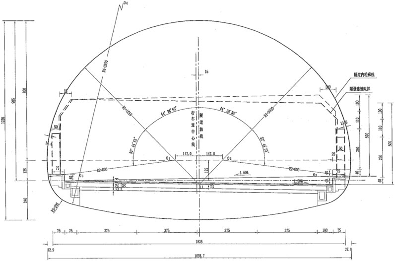
Figure 1. Tunnel construction boundary and clearance profile.
2.2 Geological conditions
The tunnel site is located in the southwest of Jiangxi Province, and its landform is obviously controlled by stratigraphic lithology and structure. The landform type in the tunnel area is denudation hills, and the ridges are mostly northeast-oriented. The elevation of the tunnel area is 320.00–420 m. The main lithology of the strata is fine biotite granite, and the surrounding rock grade of the cave body is mainly Ⅲ, IV, and partly V. The groundwater is mainly composed of network pore fissure water in weathering zone, weathering fissure water in bedrock and structural fissure water. According to the sectional calculation of the tunnel, the maximum water inflow of a single tunnel is about 487.05 m2/d, and the normal water inflow is 61.56 m/d. According to the existing operation of the Xiaowon Tunnel side ditch, the observed water inflow is 0.00078 m'/s, or 67.4 m³/d. The profile of the tunnel is shown in Figure 2.
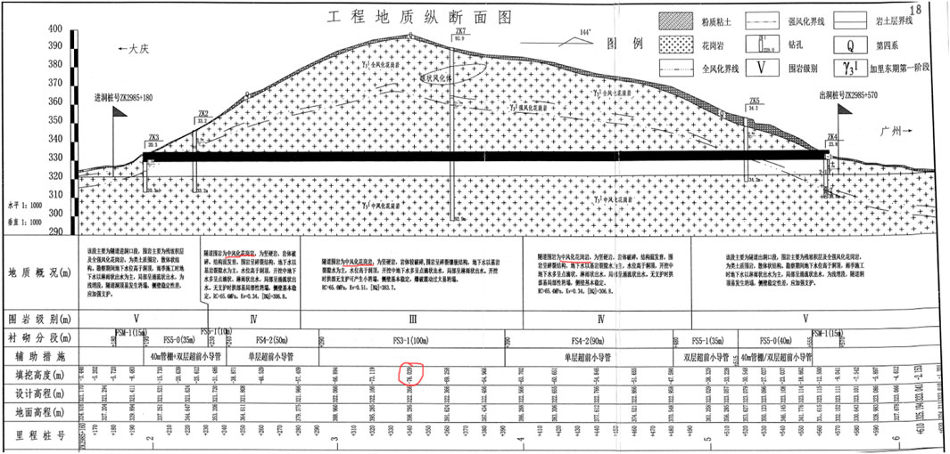
Figure 2. Tunnel longitudinal profile.
3 Tunnel numerical analysis
3.1 Model building
In this paper, the Xiaoyuan tunnel in the reconstruction and expansion project of G45 Daguang high-speed Ji 'an to Nankang section is taken as a case study, and the surrounding rock section of ZK2985+180∼ZK2985+230 Ⅴ is selected for analysis. In order to study the soil arch effect and stress change of surrounding rock after initial support, PLAXIS 3D software was used to numerically simulate the excavation and initial support of Xiaoyuan Tunnel. Figure 3 shows the 3D finite element model, the dimensions of which are 100 m in X direction, 50 m in Y direction and 100 m in Z direction. The length of the tunnel is 50 m, the maximum height is 12.25 m, the maximum width is 18.25 m, and the surrounding rock is strongly weathered granite with a thickness of 100 m. In the calculation process, the upper surface of the model is a free surface, and the horizontal displacement of the surrounding boundary is set with fixed constraints, and the bottom boundary is set with horizontal and vertical constraints.
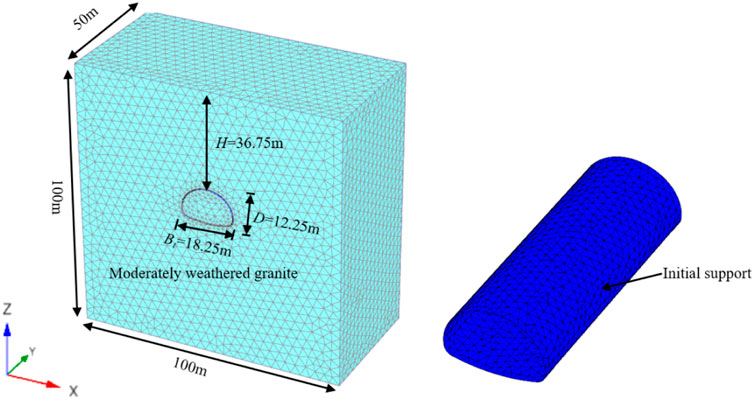
Figure 3. Tunnel model diagram.
The stress-strain curve of surrounding rock adopts Mohr-Coulomb criterion, through which the behavior of materials under stress can be predicted, and material selection and design can be made according to these predictions. In addition, the Mohr-Coulomb constitutive model can also be used in combination with other models to describe a variety of properties of materials, thus providing a more comprehensive and accurate analysis. The model was simulated by three-dimensional solid element, and the initial support was simulated by isotropic elastic plate element (Song et al., 2020). Assume that the soil is homogeneous and isotropic. The material parameters are shown in Table 1.
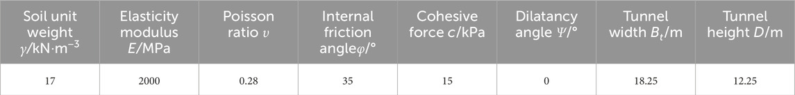
Table 1. Numerical calculation of strata and tunnel parameters.
3.2 Soil arch effect and variation of slip angle
Figure 4 shows the variation of the soil arch effect above the tunnel in different buried depth ratios of the cohesive soil layer. As can be seen from the figure, when the burial depth is relatively small, the loose area extends to the surface, and the soil mass is prone to collapse due to the inability to form a “natural arch”. With the increase of the buried depth, the soil arch effect gradually comes into play, and the range of the loose area does not reach the surface.
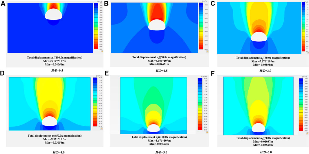
Figure 4. Variation of soil arch effect and uz of vertical displacement of tunnel in cohesive soil under different burial depth conditions.
It can be seen from Figures 5, 6 that with the increase of buried depth ratio H/D, γ angle gradually decreases (γ is the Angle between the tangent direction and the horizontal direction of the slip plane of the tunnel arch), and the boundary of the slip surface presents an elliptical track line. When the buried depth ratio of H/D is less than 1.5, the triangular sliding surface begins to form, and with the continuous increase of the buried depth of the tunnel, the sliding surface gradually becomes vertical, and the range of the loose zone also expands.
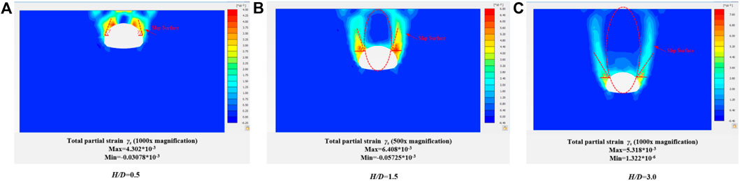
Figure 5. Changes of sliding surface above tunnel and total partial strain γs under different buried depth ratio (dilatancy angle ψ=0).
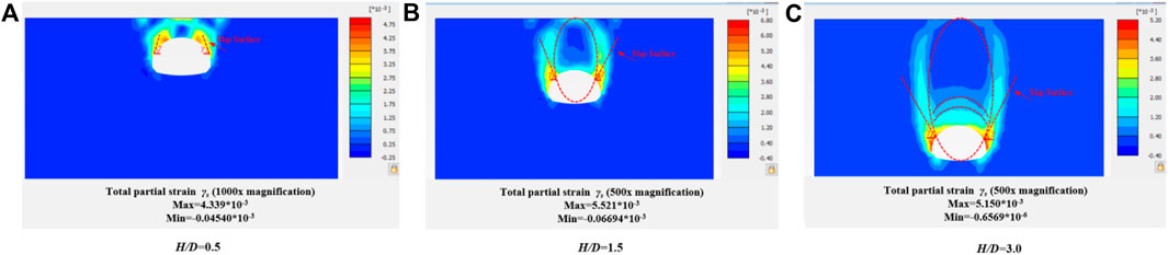
Figure 6. Changes of sliding surface above tunnel and total partial strain γs under different buried depth ratio (dilatancy angle ψ=8.75°).
According to the results of the slip ratio in Figures 5, 6, the dilatancy angle will affect the development shape of the soil arch, because the size of the dilatancy angle affects the cohesion and internal friction angle of the soil mass, and then affects the stability and deformation behavior of the soil mass. It can be found that when the dilatancy angle is small (close to 0°), the development shape of the soil arch is usually steep or vertical. This is because when the dilatancy angle is small, the cohesiveness of the soil is weak, shear failure is easy to occur, and the soil is easy to lose stability. When the dilatancy angle is large, the development shape of the soil arch is usually gentle or inclined. It is because when the dilatancy angle is larger, the cohesion of the soil mass is enhanced, the friction is also increased, the soil mass is easier to maintain stability, and the formation of a more gentle soil surface.
Increasing the dilatancy angle will enhance the resistance of soil to shear stress and reduce the deformation of soil. In the soil arch effect, appropriate dilatancy angle can increase the relative stability and bearing capacity of soil, and reduce the settlement and deformation of soil. Previously, scholars such as HOEK and BROWN (1997), based on a large amount of practical engineering experience, suggested that the dilatancy angle of rock mass with good quality, medium quality, and poor quality should be 1/4, 1/8 and 0 times the friction angle of rock mass, respectively. Therefore, the dilatancy angle was chosen as 1/4 times the internal friction angle in this paper, that is, 8.75°. As can be seen from Figure 7, there is a gap between sliding crack angles with or without dilatancy angle. With the increase of the buried depth ratio H/D, the slip angle gradually decreases, and when the buried depth ratio H/D≥3, the slip angle gradually becomes stable. On the other hand, with the increase of dilatancy angle, the slip angle decreases gradually, which makes the range of loose area increase, and thus affects the development shape of the soil arch to some extent.

Figure 7. Effect of dilatancy angle on slip angle.
3.3 Effect of cohesive soil layer on vertical stress above the tunnel
Cohesion represents the attraction between soil particles and is an important factor in maintaining the overall stability of the soil. Increasing the cohesion parameter can improve the consolidation and cohesion ability of soil mass, thereby enhancing the cohesion of soil mass and reducing the deformation. In the soil arch effect, the appropriate cohesive force parameters help improve the compressive resistance and lateral deformation resistance of the soil. As can be seen from Figure 8, under the action of the soil arch effect, the vertical stress after tunnel excavation is smaller than the initial stress. With the increase of formation cohesion, the vertical stress above the shallow buried tunnel decreases gradually. In the vertical direction, the reduction amplitude decreases from linear to curvilinear.
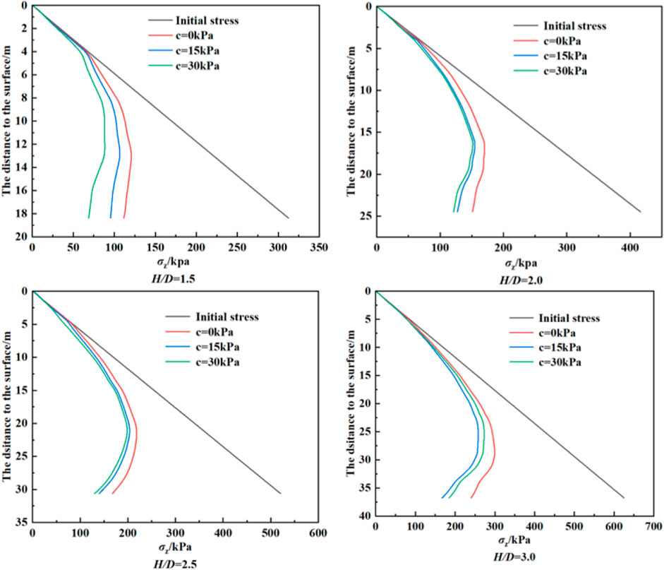
Figure 8. Effect of cohesive force on vertical stress under different buried depth ratio.
4 Calculation of loose Earth pressure
4.1 Terzaghi stratum arch
Based on the test hypothesis and boundary conditions, Terzaghi established an analytical model for calculating the loose Earth pressure of two-dimensional Earth arch effect, and obtained the expression of the loose Earth pressure σv acting on Trapdoor as follows Eq. 1:
In the formula, γ, φ, c, z, B and k are respectively soil weight, soil internal friction Angle, soil cohesion, soil thickness, Trapdoor width and side Earth pressure coefficient.
Although Terzaghi’s formula of loose Earth pressure has been widely used, there are some shortcomings: 1) the deflection of principal stress is not considered; 2) It is considered that the vertical stress on the same horizontal differential soil strip is equal; 3) Empirically determined lateral Earth pressure coefficient is 1; 4) The actual shape of the slip surface is not considered, and it is considered to be a vertical plane, and the width of the loosening zone B is also calculated on the vertical plane. Therefore, the formula in this paper will revise the above deficiencies.
4.2 Ellipsoid theory
According to the results of literature (Wu et al., 2019), the shape line of the sliding surface of the tunnel surrounding rock is an elliptic line, and the elliptic shape is also obtained through the numerical simulation results. Therefore, this paper calculates the loose Earth pressure in the tunnel from the ellipsoid theory.
The ellipsoid theory (Wu et al., 2019) states that in the structure of a silo storing particulate matter, there is usually an opening at the bottom, through which particles overflow under the action of gravity. Over time, all the spilled particles leave a space that approximates the shape of the ellipsoid, known as the outgoing ellipsoid. At the same time, a loose ellipsoid is formed between the release ellipsoid and the storage bin, and the particles in this area will loosen and produce displacement, without overflowing from the opening. Particles outside the loose ellipsoid are not affected in any way. In Figure 9, aL and bL represent the major and minor axes of the outgoing ellipsoid respectively. aJ and bJ represent the major and minor axes of the loose ellipsoid respectively. D is the tunnel diameter.
Figure 9. Theoretical model of ellipsoid.
The flatness of the ellipsoid is generally expressed by eccentricity ε, and the formula for releasing the ellipsoid ε is as follows Eq. 2:
Eccentricity ε in engineering is usually taken as 0.90∼0.98. VL and VJ represent the volumes of the released and loosened ellipsoids. Janelid and Kvapil (1966) used the looseness coefficient β to describe the relationship between the two ellipsoids. Wu et al. (2019) simplified the dimensional shrinkage problem of particulate matter into a contraction in one direction while the other direction remained infinite, thus transforming the three-dimensional problem into a two-dimensional problem. In this case, the discharged and loosened ellipsoid will be transformed into an elliptical region, and the area of this elliptical region is assumed to be equal to the area of the tunnel excavation. The calculation formula is as follows Eq. 3, 4:
According to the experimental results, the eccentricities of the released and loosened ellipsoids are assumed to be equal, and it is found that β varies in the range of 1.066∼1.100.
In combination Eqs 2, 4, the following expressions are obtained Eqs 5, 6:
Since the eccentricities of the discharged and loosened ellipsoids are equal, the following can be obtained by combining Eqs 7, 8 by combining Eqs 2–6:
4.3 Model assumption
To describe the stress state of soil under the action of the soil arch effect, the following model assumptions are proposed:
(1) The shear stress on the slip plane is in the Mohr-Coulomb limit equilibrium state.
(2) The principal stress of soil in any position at the same depth in the loosening area is equal.
(3) The soil is homogeneous and isotropic.
(4) The track line of the principal stress in loose soil is assumed to be catenary linear distribution (Chevalier et al., 2012), which replaces the uniform distribution assumption in Terzaghi theory.
4.4 Derivation of loose Earth pressure formula
It is assumed that the maximum height of the tunnel is equal to the diameter of the circle in the ellipsoid theory. The width of the loose region is taken as the distance between the intersection of the horizontal tangent line at the top of the tunnel and the loose ellipsoid. From the standard elliptic equation combined with the provision that the eccentricity of the released ellipsoid and the loose ellipsoid are equal, the half-width B of the loose region can be derived as Eq. 9:
Based on the ellipsoid theory, the paper assumes that the trace line of the small principal stress in Figure 8 is a catenary and ψ is the angle between the direction of the large principal stress σ1 and the horizontal direction at any position in the loosening region.
To facilitate the calculation, the coordinated transformation of cohesive soil is carried out Eq. 10
From the geometric relation of the molar stress circle is obtained as shown in Eqs 11–14:
Where:
Similarly, the lateral Earth pressure coefficient at any position x can be obtained Eq. 15:
Transform the coordinate system back to get Eq. 16:
Assuming that the track line of the small and medium principal stress in the soil above the tunnel is catenary line shape, and the track equation is as follows Eq. 17:
Combine Eq. 16, Eq. 17 and integrate to obtain Eq. 18:
assumptions Eq. 19:
The horizontal differential soil strip with thickness dz shown in Figure 10 is taken as the research object, and its vertical differential balance equation is as follows Eq. 20:
Figure 10. Earth pressure calculation diagram.
Combine Eqs 18–20 and according to the boundary conditions Eq. 21
Solve Eq. 22:
From Equations 10, 18, 22, the vertical stress at any position x of the overlying soil of the tunnel can be obtained Eq. 23
5 Interpretation of result
5.1 Check analysis
In order to facilitate the comparison between the formula presented in this paper and the experimental and numerical simulation results in related literatures, the vertical stress σv is normalized by using the initial stress σv(0). Figure 11 shows the comparison between the normalized formula in this paper and the experimental results and numerical simulation results in relevant literatures under non-cohesive soil layer. As can be seen from the figure, the calculation results of the revised formula in this paper are basically consistent with the test results of Shahin et al. (2008), which verifies that the application of the formula in non-cohesive soil layer is also reasonable. With the increase of the buried depth ratio of the tunnel, the difference between the loose soil pressure and the initial stress is larger, which indicates that the actual soil pressure of the tunnel is much smaller than the total soil weight under the action of the soil arch effect.
Figure 11. The vertical stress under different buried depths is normalized and compared with the experimental results in the literature.
At the same time, this paper compared the modified formula of cohesive soil with Terzaghi and Xu C et al. and found that both calculations were too large, because Terzaghi empirically believed that the lateral pressure coefficient was 1, while Xu C et al. did not consider the actual shape of the slip surface, and thought that it was a vertical plane.
Figure 12 shows the relationship between the lateral Earth pressure coefficient and internal friction angle obtained by different calculation formulas. Handy (1985) believed that as the internal friction angle increased, the coefficient of lateral Earth pressure gradually decreased, which was similar to the active Earth pressure theory. The results obtained in this paper show that the lateral Earth pressure coefficient gradually increases with the increase of the internal friction angle, which is similar to the results of the passive Earth pressure theory, and the theory in this paper can better explain that the development of soil arch effect is related to the lateral pressure coefficient.
Figure 12. The influence of the internal friction angle on the lateral Earth pressure coefficient changes.
5.2 Influence of effective internal friction angle of cohesive soil
Figure 13 shows the relationship between the angle of internal friction and the pressure of loose soil. It can be seen from the figure that with the increase of cohesion, the loose Earth pressure gradually decreases, and the decreasing range is also gradually decreasing. With the increase of the internal friction angle, the loose Earth pressure also decreases, indicating that increasing the cohesion can effectively reduce the overlying soil pressure in the strata with a large internal friction angle. On the other hand, when the tunnel buried depth ratio H/D is less than 1.0, the relationship between the internal friction angle and the loose Earth pressure presents a convex curve distribution, indicating that the loose Earth pressure decreases rapidly. When the buried depth ratio H/D is greater than 1.0, the relationship between the internal friction angle and the loose Earth pressure presents a concave curve distribution, indicating that the loose Earth pressure decreases slowly. Therefore, compared with the deep-buried tunnel, the increase of internal friction angle in the shallow-buried tunnel is more conducive to reducing the overlying soil pressure.
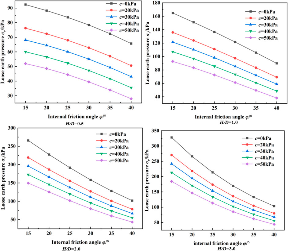
Figure 13. Relationship between internal friction angle and loose soil pressure at different buried depths.
5.3 The influence of eccentricity on the pressure of loose soil
It can be seen from Eqs 6, 7 that the major axis and minor axis of the ellipse are determined by eccentricity ε and loosening coefficient β, and thus affect the range of the loosening zone. Therefore, it is necessary to analyze the relationship between these two parameters on the loosened soil pressure.
As can be seen from Figure 14, the pressure of loose soil decreases with the increase of eccentricity ε, and the relationship is approximately linear when the eccentricity is less than 0.94. When eccentricity is greater than 0.94, the loose soil pressure decreases rapidly with the increase of eccentricity ε. On the other hand, with the increase of the loosening coefficient β, the loose Earth pressure also gradually decreases, and the influence range is about 20%. It can also be found that the influence of eccentricity ε on the pressure of loose soil is significantly greater than that of the looseness coefficient β, so the change of eccentricity ε should be paid close attention to in engineering.
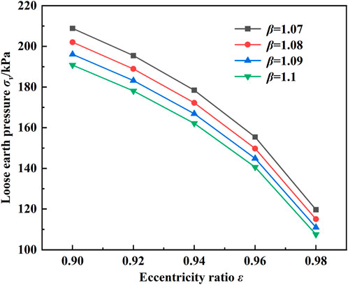
Figure 14. Diagram of the influence of eccentricity on the pressure of loose soil.
6 Conclusion
According to the numerical simulation results and ellipsoidal theory, it is concluded that the shape of the tunnel slip plane is very similar to that of the elliptic plane. Therefore, based on the ellipsoid theory, the loose soil pressure is corrected from the perspective of cohesive soil, and the principal stress deflection is considered. The rationality of the modified solution in this paper is verified by numerical simulation and relevant test results, and the following conclusions are drawn:
(1) With or without dilatancy angle, there is a gap between sliding crack angles and it will affect the development shape of the soil arch. With the increase of the buried depth ratio H/D, the slip angle gradually decreases, and when the buried depth ratio H/D≥3, the slip angle gradually becomes stable. On the other hand, with the increase of dilatancy angle, the slip angle decreases gradually, which makes the range of loose area increase, and thus affects the development shape of the soil arch to some extent.
(2) The formula in this paper agrees well with the numerical simulation and experimental results, which verifies the effectiveness of the proposed method. The coefficient of lateral Earth pressure obtained in this paper also has an obvious relationship with the change of internal friction angle.
(3) The pressure of loose soil decreases with the increase of internal friction angle and decreases with the increase of eccentricity ε and looseness coefficient β. In addition, the influence of eccentricity ε on the pressure of loose soil is greater than that of the looseness coefficient β, so the change of eccentricity ε should be paid close attention to in engineering.
Data availability statement
The original contributions presented in the study are included in the article/supplementary material, further inquiries can be directed to the corresponding author.
Author contributions
HD: Conceptualization, Data curation, Formal Analysis, Funding acquisition, Investigation, Methodology, Project administration, Resources, Software, Supervision, Validation, Visualization, Writing–original draft, Writing–review and editing. YS: Writing–original draft, Writing–review and editing. YR: Writing–review and editing, Conceptualization, Visualization. JY: Writing–original draft, Writing–review and editing. JW: Writing–original draft, Writing–review and editing. YZ: Writing–original draft, Writing–review and editing.
Funding
The author(s) declare financial support was received for the research, authorship, and/or publication of this article. This research was financially supported by the financial support from National Natural Science Foundation of China (No. 52068033), Jiangxi Provincial Department of Transportation Science and Technology Project (No. 2021Z0002, 2022Z0001, 2022Z0002), Ganpo Juncai Support Program—Training Program for Academic and Technical Leaders in Major Disciplines—Young Talents (Technical Category) (No. 20232BCJ23069),Demonstration Project of Benefiting People with Science and Technology of Qingdao, China (Grant No. 23-2-8-cspz-13-nsh).
Conflict of interest
Authors HD, YS, JY, and JW were employed by Jiangxi Transportation Institute Co., Ltd.
The remaining author declares that the research was conducted in the absence of any commercial or financial relationships that could be construed as a potential conflict of interest.
Publisher’s note
All claims expressed in this article are solely those of the authors and do not necessarily represent those of their affiliated organizations, or those of the publisher, the editors and the reviewers. Any product that may be evaluated in this article, or claim that may be made by its manufacturer, is not guaranteed or endorsed by the publisher.
References
Adachi, T., Kimura, M., and Kishida, K. (2003). Experimental study on the distribution of earth pressure and surface settlement through three-dimensional trapdoor tests. Tunn. Undergr. Space Technol. 18 (2), 171–183. doi:10.1016/s0886-7798(03)00025-7
Berthoz, N., Branque, D., Wong, H., and Subrin, D. (2018). TBM soft ground interaction: experimental study on a 1 g reduced-scale EPBS model. Tunn. Undergr. Space Technol. 72, 189–209. doi:10.1016/j.tust.2017.11.022
Cao, L., Zhang, D., Fang, Q., and Yu, L. (2020). Movements of ground and existing structures induced by slurry pressure-balance tunnel boring machine (SPB TBM) tunnelling in clay. Tunn. Undergr. Space Technol. 97, 103278. doi:10.1016/j.tust.2019.103278
Chen, R., Song, X., Meng, F., Wu, H., and Lin, X. (2022). Analytical approach to predict tunneling-induced subsurface settlement in sand considering soil arching effect. Comput. Geotechnics 141, 104492. doi:10.1016/j.compgeo.2021.104492
Chen, Y., Cao, W., and Chen, R. (2008). An experimental investigation of soil arching within basal reinforced and unreinforced piled embankments. Geotext. Geomembranes 26 (2), 164–174. doi:10.1016/j.geotexmem.2007.05.004
Chen, C., Huang, W., and Tseng, C. (2011). Stress redistribution and ground arch development during tunneling. Tunn. Undergr. Space Technol. 26, 228–235. doi:10.1016/j.tust.2010.06.012
Chevalier, B., Combe, G., and Villard, P. (2012). Experimental and discrete element modeling studies of the trapdoor problem: influence of the macro-mechanical frictional parameters. Acta Geotech. 7 (1), 15–39. doi:10.1007/s11440-011-0152-5
Costa, Y., Zornberg, J., Bueno, B., and Costa, C. (2009). Failure mechanisms in sand over a deep active trapdoor. J. Geotechnical Geoenvironmental Eng. 135 (11), 1741–1753. doi:10.1061/(asce)gt.1943-5606.0000134
Geng, Z., Jin, D., and Yuan, D. (2023). Face stability analysis of cohesion-frictional soils considering the soil arch effect and the instability failure process. Comput. Geotechnics 153, 105050. doi:10.1016/j.compgeo.2022.105050
Gong, Q., Zhang, R., Zhou, S., Tang, L., and Hang, G. (2017). Method for calculating loosening earth pressure around tunnels based on the ellipsoid theory of particle flows. Chin. J. Geotechnical Eng. 39 (01), 99–105.
Handy, R. (1985). The arch in soil arching. J. Geotechnical Eng. 111 (3), 302–318. doi:10.1061/(asce)0733-9410(1985)111:3(302)
Hoek, E., and Brown, E. T. (1997). Practical estimates of rock mass strength. Int. J. Rock Mech. Min. Sci. 34 (8), 1165–1186. doi:10.1016/s0148-9062(97)00305-7
Janelid, I., and Kvapil, R. (1966). Sublevel caving. Int. J. Rock Mech. Min. Sci. 3, 129–132. doi:10.1016/0148-9062(66)90004-0
Lee, C., Chiang, K., and Kuo, C. (2004). Ground movement and tunnel stability when tunneling in sandy ground. J. Chin. Inst. Eng. 27 (7), 1021–1032. doi:10.1080/02533839.2004.9670957
Liang, L., Xu, C., Chen, Q., and Chen, Q. (2020). Experimental and theoretical investigations on evolution of soil-arching effect in 2D trapdoor problem. Int. J. Geomechanics 20 (6), 06020007. doi:10.1061/(asce)gm.1943-5622.0001643
Rui, R., Tol, F., Xia, Y., Eekelen, S., and Hu, G. (2018). Evolution of soil arching: 2D analytical models. Int. J. Geomechanics 18 (6), 04018056. doi:10.1061/(asce)gm.1943-5622.0001169
Shahin, H. M., Nakai, T., Zhang, F., Kikumoto, M., Tabata, Y., and Nakahara, E. (2008). “Model tests and numerical simulations on shallow circular tunneling-Ground movement and earth pressure due to circular tunneling,” in Proc. of the 6th International Symposium on Geotechnical Aspects of Underground Construction in Soft Ground, USA, 29 June 2022 (IEEE), 709–715.
Shukla, S., and Sivakugan, N. (2009). A simplified extension of the conventional theory of arching in soils. Int. J. Geotechnical Eng. 3 (3), 353–359. doi:10.3328/ijge.2009.03.03.353-359
Song, Z., Tian, X., Liu, Q., Zhang, Y., Li, H., and Zhou, G. (2020). Numerical analysis and application of the construction method for the small interval tunnel in the turn line of metro. Sci. Prog. 103 (3), 36850420932067–25. doi:10.1177/0036850420932067
Wu, J., Liao, S., and Liu, M. (2019). An analytical solution for the arching effect induced by ground loss of tunneling in sand. Tunn. Undergr. Space Technol. 83, 175–186. doi:10.1016/j.tust.2018.09.025
Xu, C., Liang, L., Chen, Q., and Liu, Y. (2018). Research on loosening earth pressure considering the patterns of stress distribution in loosening zone. Rock Soil Mech. 39 (06), 1927–1934.
Xu, C., Liang, L., Chen, Q., Luo, W., and Chen, Y. (2019). Experimental study of soil arching effect under seepage condition. Acta Geotech. 14 (6), 2031–2044. doi:10.1007/s11440-019-00769-y
Keywords: soil arching effect, ellipsoid theory, clayey soil, numerical simulation, loose earth pressure
Citation: Dai H, Sun Y, Rong Y, Yu J, Wu J and Zhang Y (2024) Study on soil pressure of loose soil in cohesive soil tunnel considering soil arch effect. Front. Earth Sci. 12:1361227. doi: 10.3389/feart.2024.1361227
Received: 25 December 2023; Accepted: 08 March 2024;
Published: 05 April 2024.
Edited by:
Nibir Mandal, Jadavpur University, IndiaReviewed by:
Wei Guo, Tianjin University, ChinaZhanping Song, Xi’an University of Architecture and Technology, China
Copyright © 2024 Dai, Sun, Rong, Yu, Wu and Zhang. This is an open-access article distributed under the terms of the Creative Commons Attribution License (CC BY). The use, distribution or reproduction in other forums is permitted, provided the original author(s) and the copyright owner(s) are credited and that the original publication in this journal is cited, in accordance with accepted academic practice. No use, distribution or reproduction is permitted which does not comply with these terms.
*Correspondence: Yang Sun, eWFuZ19fX3N1bkAxNjMuY29t