 Wanwei Fang1,2
 Peng Huang
95% of researchers rate our articles as excellent or good
Learn more about the work of our research integrity team to safeguard the quality of each article we publish.
Find out more
ORIGINAL RESEARCH article
Front. Earth Sci. , 16 January 2024
Sec. Geoscience and Society
Volume 12 - 2024 | https://doi.org/10.3389/feart.2024.1338670
China’s coal mines are mainly underground mines, and a large number of roadways have to be excavated underground. It is of great significance for coal mine production to adopt safe and reasonable roadway support methods. In the process of roadway excavation, the rock stratum is inclined and the roadway pass through the layer. Since the surrounding rock conditions of the roadway passing through the layer are more complicated, it is easy to cause deformation of surrounding rock, failure and floor heave, which makes the support work difficult. In order to solve this problem, the mechanical properties of roadway surrounding rock were tested and the failure of roadway surrounding rock was analyzed using the +260 horizontal centralized transportation roadway in Changcheng No.2 mine. The surrounding rock of the roadway was divided into 8 regions, and the stress analysis of the surrounding rock in different regions was carried out. It is found that the left shoulder pit, the right side and the floor of the roadway are prone to damage. The influence of the lateral pressure coefficient, the rock dip angle and the lithology on the failure of the roadway surrounding rock was analyzed by Mohr-Coulomb failure criterion, and the specific failure range of the roadway surrounding rock was obtained. The support optimization design of the roadway was carried out, and the weak area of the surrounding rock was reinforced. The deformation monitoring of roadway surrounding rock after support optimization was carried out. The field monitoring results show that after the optimized support, the displacement of the roof and floor of the roadway section and the two sides are reduced by 43.6% and 40.8% respectively compared with the original scheme, and the deformation of the surrounding rock also shows a trend of gradual stability, and the surrounding rock of the roadway is effectively controlled. The research can provide a new way for the stress and failure analysis of the surrounding rock of the inclined rock roadway.
Coal resources play an important role in ensuring China’s energy security and economic development. The safety and reasonable support of roadways in underground coal mining is the premise to ensure the normal mining of coal (Feng, 1990; Bai and Hou, 2006; Kang et al., 2010; Zhao et al., 2020). In the actual roadway excavation process, if the roadway passes through multi-layer rock strata and the surrounding rock is inclined, the support of the roadway will become a major problem (Sun et al., 2020). A scientific analysis of the stress and damage range of the roadway and the support scheme can greatly improve the safety of underground mining.
Many scholars have studied the problem of inclined rock roadway: Wang M et al. (Wang et al., 2015a) assume that the asymmetric deformation of roadway is caused by different rock types and uneven stress distribution. Ivan Sakhno et al. (Sakhno and Sakhno, 2023) found that the plastic deformation of mudstone causes significant floor heave by studying the stress and strain distribution of surrounding rock. Gao L et al. (Gao et al., 2022) proposed that the plastic zone of the surrounding rock of inclined rock roadway expands with the increase of rock dip angle. Li G et al. (Li et al., 2023) proposed that in-situ stress and structural plane control the damage evolution model of surrounding rock by combining field investigation, theoretical analysis, similar model test, and numerical simulation. Wang X et al. (Wang et al., 2015b) proposed that the weak plane plays a role in the instability of deep inclined rock roadways. The key to maintaining the stability of a roadway is to control the shear deformation between the weak planes and the continuous deformation of soft rock area in the post-peak bearing stage after the instability of the weak plane in the surrounding rock. Xiong X et al. (Xiong et al., 2023) analyzed the deformation and failure law of roadway in an inclined coal seam according to the complex variable function theory, and put forward that the two sides of roadway, the lower side of the roof and the upper angle of lower side are the key parts of the stress concentration and deformation of the roadway. Wu G et al. (Wu et al., 2020) proposed that the maximum deformation of an inclined rock roadway occurs in the upper left and lower right of the roadway surface by numerical simulation. Tao Z et al. (Tao et al., 2018) found through physical and numerical simulation that the roof and floor of the inclined rock roadway were destroyed on the left side, and the left and right walls near the bottom were destroyed. Ma Q et al. (Ma et al., 2022) divided the surrounding rock of an inclined rock roadway into different regions and put forward surrounding rock control schemes such as grouting reinforcement, strengthening support, and pressure relief grouting for different regions. Shan R et al. (Shan et al., 2023) proposed a C-shaped tube anchor cable asymmetric support scheme for the complex asymmetric deformation characteristics of an inclined coal seam roadway and the tensile shear failure of anchor cable support. Liu P et al. (Liu et al., 2022) studied the deformation characteristics and control technology of the surrounding rock of a roadway along goaf in inclined strata and put forward the support method of anchor cable.
Many studies have also been carried out on the problem of roadway crossing: Han C et al. (Han et al., 2023) proposed that the rock mass at different depths of the roof layer showed different degrees of stress unloading, resulting in discontinuous deformation of the rock mass. Jing W et al. (Jing et al., 2022) proposed that the basic mechanical properties of the surrounding rock and the change of the in-situ stress field strength determine the number of actual deformation zones of the roadway surrounding rock and the boundary stress values of each zone. Wang J et al. (Wang et al., 2014) proposed that the cross-section of the cross-layer roadway and the inclined angle of the rock layer show the characteristics of the key parts that are destroyed first. Yu H et al. (Fan et al., 2023) proposed that tectonic stress has an important influence on the stress secondary distribution, deformation, and failure of the cross-layer roadway. Zhao Z et al. (Yu et al., 2023) conducted an in-depth analysis of the load distribution of layered roof bolts under different lithology combinations, and the results showed that cross-layer bolts were prone to tension-bending combined deformation near the bedding plane. Wang L et al. (Zhao et al., 2018) established the stability analysis model of the cross-layer roadway, determined the stability grade of the cross-layer roadway under different working conditions, and proposed the partition combined support scheme of the cross-layer roadway. Xie Z et al. (Wang et al., 2019) studied the failure mode and instability mechanism of surrounding rock of different cross-layer roadways by combining field tests and numerical simulation and proposed a support scheme of ‘fast thick layer end anchoring + full-length lagging grouting anchoring + secondary continuous reinforcement.
The above methods of numerical simulation, field observation, and theoretical analysis are used to summarize and study the causes and deformation laws of asymmetric deformation of inclined rock roadways and cross-layer roadways, and the methods of strengthening support are put forward. However, there are few studies on the stress and failure mechanism of surrounding rock in inclined strata. In this paper, through the combination of theoretical analysis and field practice, the control problem of surrounding rock of inclined strata crossing the roadway in a kilometer-deep well is studied. The failure of the surrounding rock of the roadway is analyzed. The surrounding rock of the roadway is divided into regions, and the stress analysis of the surrounding rock in different regions is carried out. The Mohr-Coulomb failure criterion is used to analyze the influencing factors of surrounding rock failure of roadways. The failure range of the surrounding rock of roadway is obtained, and the weak area of surrounding rock is strengthened. This paper breaks the tradition of designing support methods by experience in the past and provides a new method for the stress, failure analysis, and support optimization of the surrounding rock of the inclined rock tunnel.
The second mine is located on the east bank of the Yellow River, north of the ancient Great Wall, at the junction of the Inner Mongolia Autonomous Region and the Ningxia Hui Autonomous Region, the mine design scale is 4 million tons/year. The mine adopts multi-level development, in which the +260 horizontal centralized transportation roadway is a cross-layer roadway. The designed length of the roadway is 2,600 m, and the buried depth is nearly one thousand meters. The surrounding rock of the roadway is inclined about 30° to the left, and the opening point of the roadway is located in the sandy mudstone of the 7-coal roof. During the excavation, the 7-coal roof is penetrated to the 5-coal roof, and then the 5-coal roof to the 7-coal floor. Due to the poor surrounding rock conditions of the roadway, the damage to some sections during the excavation of the roadway is shown in Figure 1.
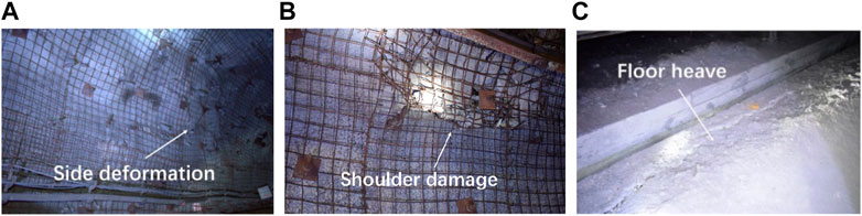
FIGURE 1. Roadway site damage. (A) Side deformation (B) Shoulder damage (C) Floor heave.
The rock samples were obtained at a distance of 400 m from the opening point of the roadway in the + 260 m horizontal cross-layer of the roadway. According to the ISRM specification, the rock block is made into a standard rock sample (Xie et al., 2023). Table 1 shows the compressive strength, tensile strength, cohesion, internal friction angle, softening coefficient, and density of the rock samples tested in the laboratory.
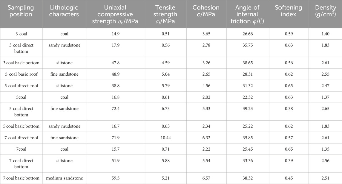
TABLE 1. Experimental results of physical and mechanical properties of coal rock.
The original support of the main roadway adopts spray anchor (cable) spray and anchor (rod) net spray. The primary support anchor cable is made of steel strand with 1 × 7 structure, the specification is Φ21.6 mm × L6300 mm, and the row spacing is 1,200 × 1,200 mm. The secondary support bolt adopts MSGLD-600 (X), with equal strength screw steel type resin bolt (Φ22 mm × L2400 mm), and the row spacing is 1,200 mm × 1,200 mm. The anchor net is made of Φ6.0 mm steel mesh, and the grid is 100 × 100 mm. The specific arrangement of the supports is shown in Figure 2.
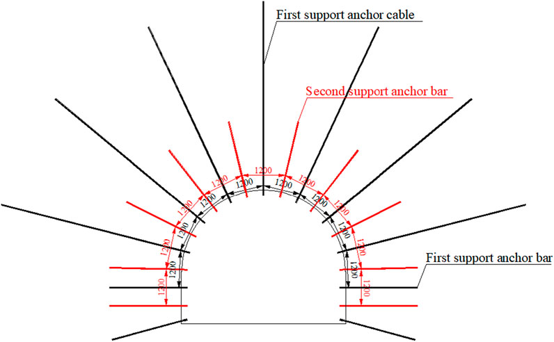
FIGURE 2. Roadway support scheme.
Due to the long roadway, the geological data of different boreholes have been used, and the occurrence of roadway surrounding rock is shown in Figure 3.
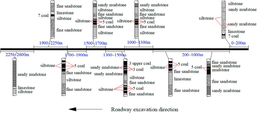
FIGURE 3. Occurrence of roadway surrounding rock.
It can be seen from Figure 3 that from the opening of the + 260 horizontal roadway to the 1,000 m of the roadway, the rock strata change slowly, and the roof and floor have relatively hard rock strata. The support pressure is relatively low. From 1,000 m to 2,250 m, the ups and downs of the rock strata are constantly changing. The 5-coal and 7-coal are all crossed to the side of the roadway, and the lithology of the roof and floor is also constantly changing. The support pressure is large. From 2,250 m to 2,600 m, the change of rock strata tends to be stable, but the entire roadway consists of sandy mudstone. The strength of the surrounding rock is weak, and it is easy to soften in water. The surrounding rock condition is poor, which is one of the serious damage areas of the roadway and the support pressure is large.
Before the excavation of the roadway, the rock mass is in an elastic equilibrium state under the initial stress. After excavation, due to the removal of part of the rock, the surrounding rock mass of the roadway lost its original support force and displacement constraints, which in turn cause a tendency to move inward. The displacement of the surrounding rock mass of the roadway caused the displacement of the deep rock mass, which continued to a certain depth. Simultaneously with the displacement, the stress of the rock mass is readjusted inward from the surface to maintain mechanical balance (Fairhurst and Hudson, 1999; Aydan, 2019).
When the burial depth is large, the variation of vertical ground stress in the influence range of roadway excavation is smaller than that of the original rock stress, and the linear increase of vertical stress can be ignored. The vertical stress at the buried depth of the roadway is approximately the upper and lower boundary load. When the lateral pressure coefficient is constant, the horizontal stress is also evenly distributed. Therefore, the mechanical model is further defined as the opening problem of an infinite plate subjected to two-way pressure. As shown in Figure 4, when the lateral pressure coefficient is 1, the problem can be simplified to an axisymmetric thick-walled cylinder model.
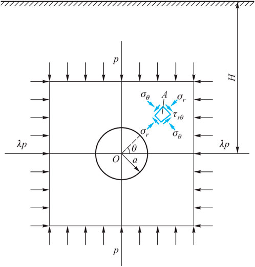
FIGURE 4. Stress state of surrounding rock in circular roadway.
A circular roadway of radius a is excavated at a depth of H from the surface, and H >> a. This problem can be viewed as a stress distribution problem of an infinite plate orifice under bidirectional compression. The analysis was first solved by the German engineer G. Kirsch in 1898. Take the unit A (r, θ) (θ is the angle between OA and the horizontal axis) at r from the center of the circular roadway, and the stress at point A is shown in Formula 1 (Elasticity, 2014).
In the formula: σr——normal stress, σθ——tangential stress, λ——side pressure coefficient, p——original rock stress.
Under the stress of plateau rock in deep inclined roadways, the influence of the dip angle of roadway surrounding rock on the deformation and failure of roadway surrounding rock is obviously increased compared with that of shallow buried roadway. The traditional horizontal or horizontal roadway generally divides the surrounding rock of the roadway into four areas, which are the roof, two sides, and floor of the roadway (Mumtaz, 2017). However, due to the existence of the dip angle of the surrounding rock of the roadway, the inclined rock roadway needs a more detailed regional division. According to the relationship between the layered surrounding rock of the roadway and the position of the roadway and the deformation difference of the surrounding rock of the roadway, the surrounding rock of the roadway is divided into different regions, as shown in Figure 5.
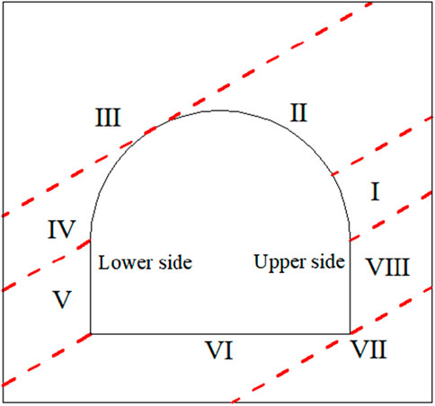
FIGURE 5. The stress division of surrounding rock of roadway.
It can be seen from Figure 5 that due to the excavation of the roadway, the integrity of the rock strata is damaged, which also affects the stress characteristics of the rock mass in the area. The surrounding rock is divided into eight areas, of which the integrity of the rock strata in the III and VII areas is not damaged. The roadway roof is divided into three partitions due to the different stress conditions and deformation mechanisms, which are I, II, and IV areas.
Due to the excavation of the roadway, the normal stress on the roadway surface rotates parallel to the roadway surface. When the dip angle of the inclined surrounding rock is θ, the stress in the surrounding rock of roadway surface appears as a tangential force σθ and as a normal force σr. On the surface of the roadway, the normal stress is zero, only the tangential stress. The tangential stress is different at different positions on the surface of the roadway and the dip angle of the rock strata. The normal principal stress gradually increases in the surrounding rock of the roadway.
The stress diagram of each partition of the roadway is shown in Figure 6.
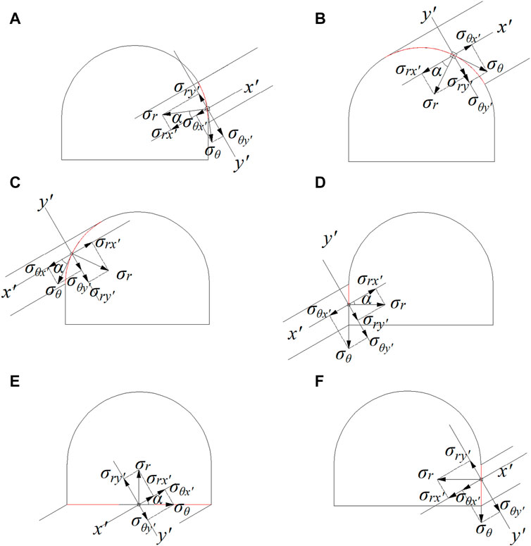
FIGURE 6. The stress diagram of each partition of roadway. (A) I (B) II (C) IV (D) V (E) VI (F) VIII.
From Figure 6, it can be seen that the stress in the rock mass can be decomposed into the force in the bedding direction and the force perpendicular to the direction of the rock layer, where x′ is the inclination direction of the rock layer, and y′ is the normal direction of the rock layer. Without considering the influence of gravity, the stress expressions of the surrounding rock in each area are as follows:
In the formula: θ is the dip angle of the rock strata, α is the angle between the tangent of the roadway surface and the inclination of the rock strata, where the positive value indicates that the direction of the force points to the inside of the roadway surrounding rock, and the negative value indicates that it points to the outside of the roadway.
From the above analysis, it can be seen that due to the inclination of the rock stratum, the stress of the roadway is not uniform. The component force of the rock strata at the left shoulder fossa points vertically to the roadway, and the pressure is large. The component force acts on the exposed rock mass, and in the process of roadway crossing, the thickness of the surrounding rock on the left side becomes thinner and thinner, which makes it easy to cause damage. At the floor of the roadway, when the rock force is transmitted downward, it is easy to squeeze each other and form a floor heave phenomenon.
The Mohr-Coulomb yield criterion is a yield theory that considers the maximum shear stress or single shear stress under normal stress. It can be used to analyze the influence of one or several parameters on mining pressure behavior and roadway surrounding rock deformation, and the effect is clear and intuitive (Duncan Fama and Pender, 1980). The roadway section is simplified as a circle, and the Mohr-Coulomb failure criterion is used to check the failure of the rock surrounding the roadway surface in different regions according to the different influencing factors (lateral pressure coefficient, rock dip angle, lithology).
The condition of roadway surrounding rock failure is
Based on the Mohr-Coulomb failure criterion, the influence of the lateral pressure coefficient, the rock dip angle and the lithology on the failure range of the roadway is analyzed.
When the dip angle α = 30°, the failure area of the roadway surface when the lateral pressure coefficient is equal to 1,1.2,1.4,1.6 is analyzed by Formula 15, as shown in Figure 7.
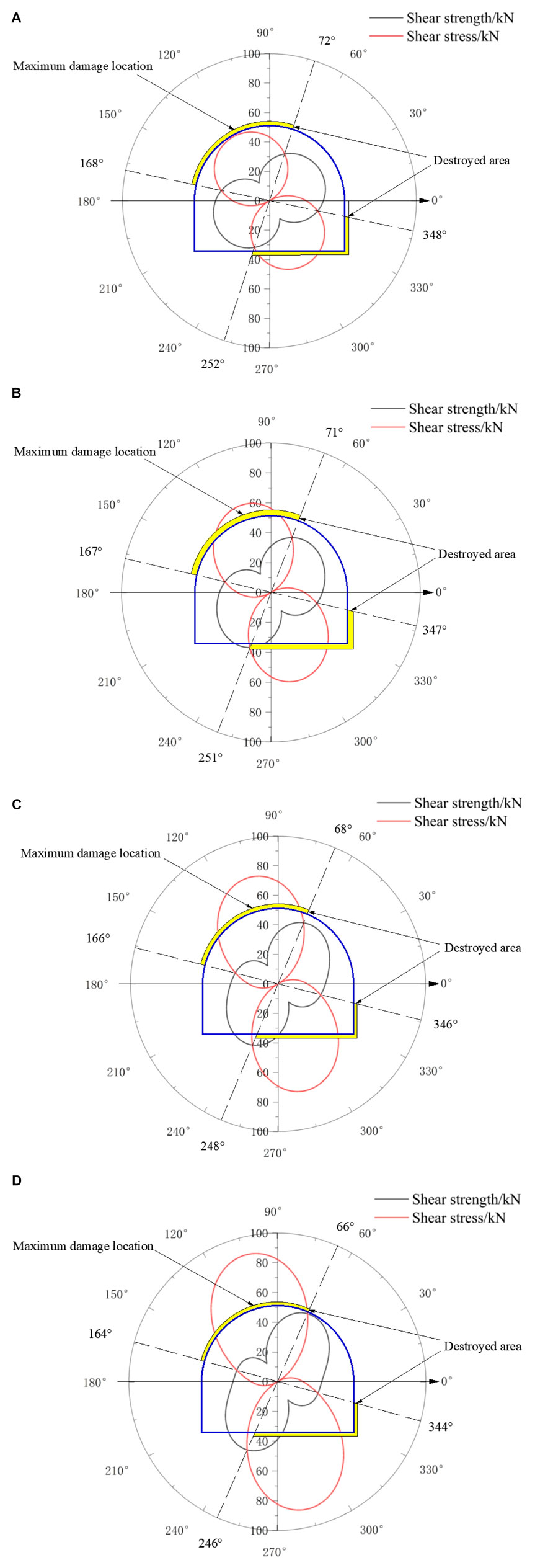
FIGURE 7. The damage range of the surface roadway with different lateral pressure coefficients. (A) λ = 1.0 (B) λ = 1.2 (C) λ = 1.4 (D) λ = 1.6.
The lateral pressure coefficient is a physical quantity used to describe the state of ground stress. It can be seen from the results of Figure 7 that the surface failure area of the roadway is on the left side of the roof, the right side of the floor and the lower part of the upper side, the failure range of surrounding rock shows the shape of ‘8'. The larger the lateral pressure coefficient is, the more obvious the shape of ‘8’ is. When λ= 1,1.2,1.4 and 1.6, the failure range reaches 96°, 96°, 98° and 98° respectively. The maximum failure position is on the left side of the roof. Combined with the existing research results, it can be seen that when the lateral pressure coefficient increases, the shear stress of the surrounding rock of the roadway increases significantly, the degree of roadway failure will increase, and the overall failure range of the roadway increases slightly (Xu et al., 2008; Shafiq and Subhash, 2016; Yin et al., 2019; Yin et al., 2021; Yin et al., 2022).
When the value of lateral pressure coefficient is 1, the failure area of the roadway surface is analyzed by Formula 5 when the dip angle of the roadway rock stratum is 0°, 15°, 30°, 45°, 60° and 75°, as shown in Figure 8.
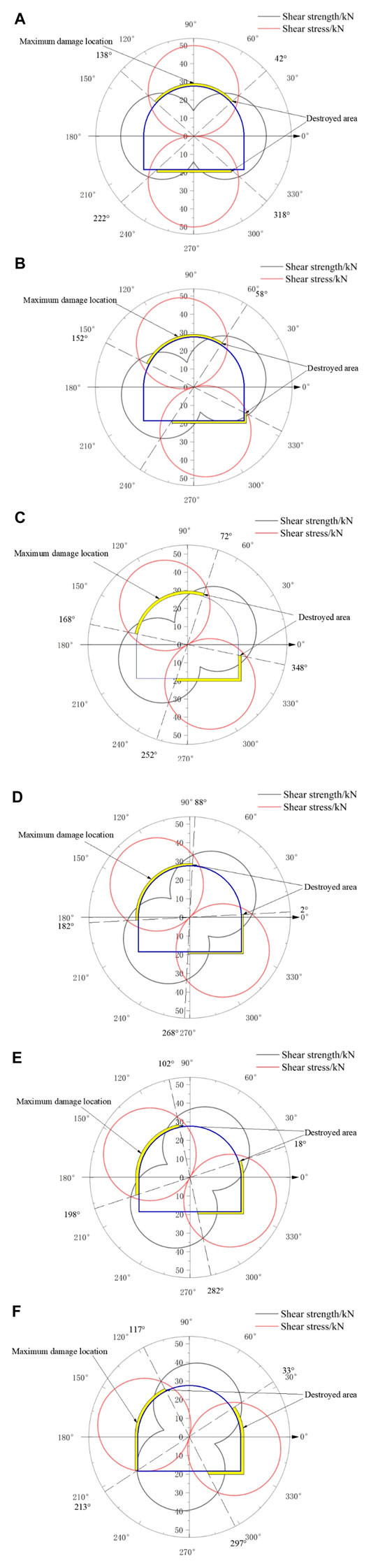
FIGURE 8. The surface failure range of roadway with different rock dip angles. (A) dip angel is 0° (B) dip angel is 15° (C) dip angel is 30° (D) dip angel is 45° (E) dip angel is 60° (F) dip angel is 75°.
The dip angle of the surrounding rock mainly affects the failure position of the roadway. The stress and deformation of the surrounding rock of the roadway in steeply dipping coal and rock strata are asymmetric. When the dip angle increases, the failure position of the roadway surrounding rock changes, and the failure range of the roadway does not change. When the dip angle of rock stratum changes to 0°, 15°, 30°, 45°, 60° and 75°, the maximum failure positions of roof are 90°, 105°, 120°, 135°, 150° and 165° respectively. The maximum failure position is parallel to the tangent of the roadway roof to the tendency of the rock strata, and the degree of failure does not change. With the increase of the dip angle of the rock strata, the bending deformation of the rock strata gradually changes to the bedding slip deformation. In addition, due to the large inclination angle of the coal rock bedding surface, the vertical load, and the self-weight of the rock mass are unfavorable to the stability of the bedding surface, it is easy to appear coal seam failure and deformation outburst phenomenon. The circular section can reduce the stress concentration of the roadway roof and the two sides, rationalize the stress distribution of the surrounding rock, and improve the overall support effect of the roadway. The roof stress distribution of the semi-circular arch roadway is relatively uniform, but the control effect on the two sides is not obvious (Jia et al., 2011; Jing et al., 2013).
When the lateral pressure coefficient is 1 and the dip angle of the rock strata is 30°, the failure area of the roadway surface under different lithology is analyzed by Formula 15, as shown in Figure 9.
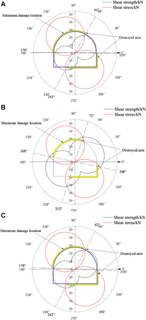
FIGURE 9. Roadway surface damage area in different lithology. (A) coal (B) sandstone (C) mudstone.
The lithology mainly affects the strength of the surrounding rock. When the strength of the surrounding rock increases, the damage range decreases and the damage degree decrease as well.
The actual exposure analysis of the on-site roadway shows the rock strata are inclined to the left by nearly 30°. The nearest distance between the 5-coal and the roof of the roadway is less than 2m, as shown in Figure 10.
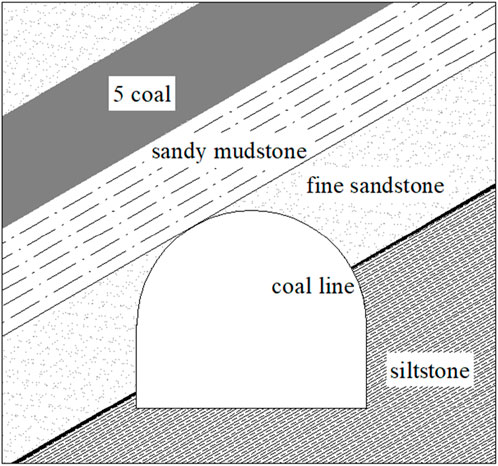
FIGURE 10. Roadway section.
The failure area of the roadway surface can be obtained from the test results of the mechanical properties of the surrounding rock of the roadway and Formula (15), as shown in Figure 11.

FIGURE 11. Damage range of roadway.
It can be seen from Fig.11 that the failure area of the + 260 horizontal concentrated roadway in the Great Wall No.2 Mine is mainly on the left side of the roof (near the lower side), the right side (upper side) and the right side of the floor (near the upper side), which is basically consistent with the field situation.
Through the actual situation of the roadway on-site and the above analysis, it can be obtained that the support should be strengthened in the weak area of the roadway, and the row spacing between the bolts (cables) should be reduced. At the same time, considering that the distance between the left shoulder fossa of the roadway and the 5 coal is relatively close, the length of the anchor cable should be lengthened to make it anchored in the hard rock layer. The specific support scheme is as follows:
The primary support of the roadway adopts Φ21.8 mm × L6300 mm anchor cable support, the row spacing is 1,200 × 1,200 mm, and the row spacing at the left shoulder fossa is 900 × 1,200 mm. The bolt adopts MSGLD-600 (X) equal strength screw steel type resin bolt (Φ22 mm × L2400 mm). The row spacing is 1,000 × 1,200 mm. The anchor net adopts φ6.0 mm warp and weft steel mesh, and the mesh size is 100 × 100 mm.
The secondary support bolt of the roadway adopts MSGLD-600 (X) and other strong thread steel resin bolt (Φ22mm × L2400 mm), the right shoulder socket is 1,200 × 1200mm, and the two sides are 1,000 × 1200 mm. The left shoulder fossa is supported by Φ21.8 × 8300 mm anchor cable, and the row spacing is 900 × 1200 mm. The bottom angle is supported by 2 bolts. The mesh adopts φ6.0 mm warp and weft steel mesh, and the mesh size is 100 × 100 mm. The specific arrangement is shown in Figure 12.
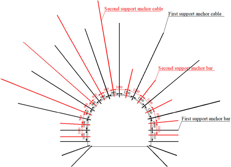
FIGURE 12. Roadway support optimization design.
The monitoring equipment for the layout of the cross-layer roadway is mainly to observe the data of the mine pressure and the deformation of the surrounding rock during the excavation period and the mining period of the working face. The monitoring points are mainly set up along the 800 m excavation in front of the roadway, and 17 monitoring stations are set up in the roadway. The 1 # station is 20 m away from the initial excavation position of the roadway, and the distance between the stations is 50 m. The length of each station is 10 m, and the monitoring equipment is arranged in a range of 10 m for observation. The arrangement is shown in Figure 13 (Fan et al., 2021; Tian et al., 2022). Multi-point displacement sensors are used within the measuring station to monitor the deformation of the surrounding rock of the tunnel.
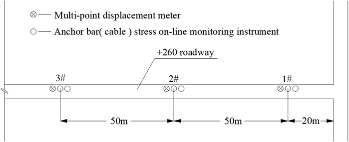
FIGURE 13. Layout of roadway monitoring equipment.
Based on the comprehensive analysis of the observation data of the bed separation instrument and the surrounding rock station, the deformation characteristics of the roof and floor of the surrounding rock and the two sides of the + 260 main roadway under the condition of surrounding rock stress can be obtained. The deformation characteristics of the roof and floor of the surrounding rock and the two sides of the roadway are shown in Figures 14, 15.
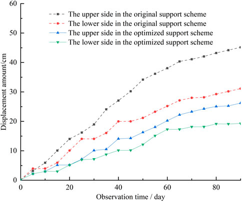
FIGURE 14. The displacement comparison curve of the two sides of the original scheme and the optimization scheme.
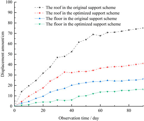
FIGURE 15. The comparison curve of the displacement of the roof and floor of the original scheme and the optimization scheme.
From Figures 14, 15, it can be seen that the displacement of the two sides is reduced after the optimization of the support scheme. The maximum displacement of the 2 months decreased from 45 mm to 31 mm of the original scheme to 26mm and 19 mm respectively, and the displacement of the two sides decreased by 40%. At the same time, it can be seen from the deformation curve that the deformation of the original scheme does not show a gentle and stable trend, while the deformation of the surrounding rock of the optimized support scheme shows a gradually stable trend. After optimizing the support scheme, the deformation of the roof and floor is reduced. The maximum floor heave and maximum roof subsidence in 2 months decreased from 75 mm to 26 mm of the original scheme to 41 mm and 16mm, respectively. The amount of roof and floor movement decreased by 43.6%. At the same time, it can be seen from the deformation curve that the floor heave speed of the original scheme is still increasing, while the floor heave and roof subsidence of the new scheme are gradually stable.
The field observation shows that the asymmetric support of the roof and the anchor cable reinforcement of the two sides and the bottom angle can adapt to the deep high-stress environment and effectively reduce the deformation of the surrounding rock of the roadway.
In this paper, the method of theoretical analysis and field practice is used to analyze the stress state and failure range of surrounding rock of inclined strata crossing roadway with the background of + 260 horizontal centralized transportation roadway in Great Wall No. 2 Coal Mine, and the support optimization design is carried out. The specific conclusions are as follows:
(1) In the left shoulder fossa, the rock force of the roadway is perpendicular to the roadway, the pressure is large, and the force is applied to the exposed rock block. In the process of roadway crossing, the thickness of the surrounding rock on the left side becomes thinner and thinner, which is easy to cause damage.
(2) When the lateral pressure coefficient increases, the shear stress on the surrounding rock of the tunnel significantly increases, the degree of tunnel damage increases, and the range of damage increases; When the inclination angle of the rock layer changes, the location of the surrounding rock damage in the tunnel changes, and the range of damage remains unchanged. The maximum damage location is at the position where the tangent line of the tunnel roof is parallel to the inclination of the rock layer; When the strength of the surrounding rock increases, the deformation resistance of the roadway increases, the range of damage decreases, and the degree of damage decreases.
(3) The support optimization design is carried out for the left shoulder pit, the upper side of the roadway, and the floor, which reduces the spacing of the bolt (cable). Four anchor cables are added to the left shoulder socket, and one anchor bolt is added to the two sides and the bottom corner of the roadway.
(4) The deformation of the roadway is controlled after optimized support. The results show that after optimized support, the displacement of the roof and floor of the roadway section and the two sides are reduced by 43.6% and 40.8% respectively compared with the original scheme. The deformation of the surrounding rock also has a gradual stability trend, and the surrounding rock of the roadway is effectively controlled.
The original contributions presented in the study are included in the article/Supplementary material, further inquiries can be directed to the corresponding author.
WF: Writing–review and editing. ML: Writing–review and editing. PH: Writing–original draft. TS: Writing–review and editing. YC: Writing–review and editing. YL: Writing–review and editing. SM: Writing–review and editing. GR: Writing–original draft.
The author(s) declare financial support was received for the research, authorship, and/or publication of this article. This research was funded by the National Natural Science Foundation of China (52104105) and the Key Laboratory of Deep Earth Science and Engineering (Sichuan University), Ministry of Education (DESE202203).
Author WF was employed by Xinkuang Inner Mongolia Energy Co., Ltd. Authors ML, TS, YC, and SM were employed by Inner Mongolia Fucheng Mining Co., Ltd.
The authors declare that the research was conducted in the absence of any commercial or financial relationships that could be construed as a potential conflict of interest.
All claims expressed in this article are solely those of the authors and do not necessarily represent those of their affiliated organizations, or those of the publisher, the editors and the reviewers. Any product that may be evaluated in this article, or claim that may be made by its manufacturer, is not guaranteed or endorsed by the publisher.
Bai, J., and Hou, C. (2006). Deep roadway surrounding rock control principle and application research. J. China Univ. Min. Technol. (02), 145–148. doi:10.1093/carcin/bgm010
Duncan Fama, M. E., and Pender, M. J. (1980). Analysis of the hollow inclusion technique for measuring in situ rock stress. Int. J. Rock Mech. Min. Sci. 17 (3), 137–146. doi:10.1016/0148-9062(80)91360-1
Fairhurst, C. E., and Hudson, J. A. (1999). Draft ISRM suggested method for the complete stress–strain curve for the intact rock in uniaxial compression. Int. J. Rock Mech. Min. 36 (3), 279–289. doi:10.1016/S0148-9062(99)00006-6
Fan, S., Song, Z., Li, X., Zhang, Y., and Liu, L. (2023). Investigation into the large deformation mechanism and control technology of variable cross-section tunnel in layered mudstone stratum. Buildings 13 (1), 110. doi:10.3390/buildings13010110
Fan, S., Song, Z., Xu, T., Wang, K., and Zhang, Y. (2021). Tunnel deformation and stress response under the bilateral foundation pit construction: a case study. Archives Civ. Mech. Eng. 21, 109. doi:10.1007/s43452-021-00259-7
Feng, Y. (1990). Research on soft rock roadway support in China. Mine Press. roof Manag. (02), 42–44.
Gao, L., Zhan, X., Zhang, P., Wen, Z., Ma, Z., Kong, D., et al. (2022). Study on the dip angle effect of asymmetric deformation and failure of the gob-side coal-rock roadway in gently inclined coal seam. Sustainability 14 (12), 7299. doi:10.3390/su14127299
Han, C., Zhang, N., Yang, H., Zhao, Q., and Song, K. (2023). Discontinuous deformation characteristics of deep buried roadway roofs and linkage control of thick layer cross-boundary anchorage: a case study. Energies 16 (5), 2160. doi:10.3390/en16052160
Jia, S., Wang, J., and Zhu, J. (2011). Calculation and application on elastic-plastic coal pillar width of the stope. ISMSSE, 26. doi:10.1016/j.proeng.2011.11.2282
Jing, W., Liu, S., Yang, R., Jing, L., and Xue, W. (2022). Mechanism of aging deformation zoning of surrounding rock in deep high stress soft rock roadway based on rock creep characteristics. J. Appl. Geophys. 202, 104632. doi:10.1016/j.jappgeo.2022.104632
Jing, Z., Xie, F., Cui, X., and Zhang, J. f. (2013). Modern tectonic stress field deeply in xuzhou coal mine. Int. J. Coal Sci. Technol. 19 (1), 14–18. doi:10.1007/s12404-013-0103-x
Kang, H., Wang, J., and Lin, J. (2010). Application example analysis of bolt support in coal mine roadway. J. Rock Mech. Eng. 29 (04), 649–664.
Li, G., Sun, Q., Ma, F., Guo, J., Zhao, H., and Wu, Y. (2023). Damage evolution mechanism and deformation failure properties of a roadway in deep inclined rock strata. Eng. Fail. Anal. 143, 106820. doi:10.1016/j.engfailanal.2022.106820
Liu, P., Gao, L., Zhang, P., Wu, G., Wang, C., Ma, Z., et al. (2022). A case study on surrounding rock deformation control technology of gob-side coal-rock roadway in inclined coal seam of a mine in guizhou, China. Processes 10 (5), 863. doi:10.3390/pr10050863
Ma, Q., Zhang, Y., Zhang, X., Li, Z., Song, G., Cheng, J., et al. (2022). The failure law and control technology of large-section roadways in gently inclined soft coal seams. Processes 10 (10), 1993. doi:10.3390/pr10101993
Sakhno, I., and Sakhno, S. (2023). Numerical studies of floor heave mechanism and the effectiveness of grouting reinforcement of roadway in soft rock containing the mine water. Int. J. Rock Mech. Min. Sci. 170, 105484. doi:10.1016/j.ijrmms.2023.105484
Shafiq, M., and Subhash, G. (2016). An extended mohr-coulomb model for fracture strength of intact brittle materials under ultrahigh pressures. J. Am. Ceram. Soc. 99 (2), 627–630. doi:10.1111/jace.14026
Shan, R., Li, T., Liu, W., Chen, Y., Shi, S., and Li, G. (2023). Study on asymmetric support of anchor cable with C-shaped tube in inclined coal seam roadway. Appl. Sci. 13 (14), 8088. doi:10.3390/app13148088
Sun, S., Zhao, C., Zhang, Y., Du, S., Xin, B., Xiao, G., et al. (2020). Study on deformation characteristics and repair and reinforcement technology of surrounding rock in multi-coal seam repeated mining roadway. J. Min. Saf. Eng. 37 (04), 681–688. doi:10.13545/j.cnki.jmse.2020.04.005
Tao, Z., Zhu, C., Zheng, X., Wang, D., Liu, Y., He, M., et al. (2018). Failure mechanisms of soft rock roadways in steeply inclined layered rock formations. Geomatics Nat. Hazards Risk 1 (9), 1186–1206. doi:10.1080/19475705.2018.1497712
Tian, X., Zhang, S., Wang, H., Zhang, Y., and Wang, J. (2022). Evolution characteristics of the surrounding rock pressure and construction techniques: a case study from Taoshuping tunnel. Tunn. Undergr. Space Technol. 125, 104522. doi:10.1016/j.tust.2022.104522
Wang, J., Guo, Z., Cai, F., Hao, Y., and Liu, X. (2014). Study on asymmetric deformation mechanism and control countermeasures of deep cross-layer roadway. J. Min. Saf. Eng. 31 (01), 28–33. doi:10.13545/j.issn1673-3363.2014.01.005
Wang, L., Wang, Q., Huang, Y., Zhang, H., Jiang, B., Xu, Y., et al. (2019). Research on deformation mechanism and support technology of deep high stress roadway. J. Min. Saf. Eng. 36 (01), 112–121.
Wang, M., Guo, G., Wang, X., Guo, Y., and Dao, V. (2015a). Floor heave characteristics and control technology of the roadway driven in deep inclined-strata. Int. J. Min. Sci. Technol. 25, 267–273. doi:10.1016/j.ijmst.2015.02.016
Wang, X., Bai, J., and Wang, M. (2015b). Mechanism and control technology of asymmetric instability of deep inclined rock roadway under the influence of weak plane. J. Min. Saf. Eng. 32 (04), 544–551.
Wu, G., Chen, W., Jia, S., Tan, X., Zheng, P., Tian, H., et al. (2020). Deformation characteristics of a roadway in steeply inclined formations and its improved support. Appl. Math. Model. 130, 104324. doi:10.1016/j.ijrmms.2020.104324
Xie, Z., He, Z., Xiang, Z., Zhang, N., Su, J., Li, Y., et al. (2023). Deformation failure characteristics and maintenance control technologies of high-stress crossing-seam roadways: a case study. Appl. Science-basel 13 (7), 4442. doi:10.3390/app13074442
Xiong, X., Ouyang, Y., Jun, D., and Zhang, L. (2023). Analysis and control of self-stable balance circle of surrounding rock of roadway in inclined coal seam. Sci. Rep. 124, 749–767. doi:10.1016/j.apm.2023.08.020
Xu, X., Gao, F., Gao, Y., and Xie, H. (2008). Effect of high temperatures on the mechanical characteristics and crystal structure of granite. J. China Univ. Min. Technol. 37 (3), 402–405. doi:10.3321/j.issn:1000-1964.2008.03.024
Yin, Q., Liu, R., Jing, H., Su, H., Yu, L., and He, L. (2019). Experimental study of nonlinear flow behaviors through fractured rock samples after high temperature exposure. Rock Mech. Rock Eng. 52, 2963–2983. doi:10.1007/s00603-019-1741-0
Yin, Q., Wu, J., Jiang, Z., Zhu, C., Su, H., Jing, H., et al. (2022). Investigating the effect of water quenching cycles on mechanical behaviors for granites after conventional triaxial compression. Geomechanics Geophys. Geo-Energy Geo-Resources 8, 77. doi:10.1007/s40948-022-00388-0
Yin, Q., Wu, J., Zhu, C., He, M., Meng, Q., and Jing, H. (2021). Shear mechanical responses of sandstone exposed to high temperature under constant normal stiffness boundary conditions. Geomechanics Geophys. Geo-Energy Geo-Resources 7 (2), 35–17. doi:10.1007/s40948-021-00234-9
Yu, H., Liu, H., Xia, Y., Zhang, M., Hang, Y., and Luo, W. (2023). A study on the deformation mechanism of the rock surrounding a weakly cemented cross-layer roadway, under tectonic stress. Energies 16 (6), 2546. doi:10.3390/en16062546
Zhao, C., Li, Y., Liu, G., and Meng, X. (2020). Mechanism analysis and control technology of surrounding rock failure in deep soft rock roadway. Eng. Fail. Anal. 115, 104611. doi:10.1016/j.engfailanal.2020.104611
Keywords: deep coal mine, inclined rock strata, cross-layer roadway, stress analysis, support optimization: surrounding rock control
Citation: Fang W, Li M, Huang P, Shi T, Chen Y, Ma S and Ren G (2024) Study on failure mechanism and control of surrounding rock of inclined strata crossing roadway in deep coal mine. Front. Earth Sci. 12:1338670. doi: 10.3389/feart.2024.1338670
Received: 15 November 2023; Accepted: 03 January 2024;
Published: 16 January 2024.
Edited by:
Wen Nie, Jiangxi University of Science and Technology, ChinaReviewed by:
Chun Zhu, Hohai University, ChinaCopyright © 2024 Fang, Li, Huang, Shi, Chen, Ma and Ren. This is an open-access article distributed under the terms of the Creative Commons Attribution License (CC BY). The use, distribution or reproduction in other forums is permitted, provided the original author(s) and the copyright owner(s) are credited and that the original publication in this journal is cited, in accordance with accepted academic practice. No use, distribution or reproduction is permitted which does not comply with these terms.
*Correspondence: Peng Huang, Y3VtdF9ocEAxMjYuY29t
Disclaimer: All claims expressed in this article are solely those of the authors and do not necessarily represent those of their affiliated organizations, or those of the publisher, the editors and the reviewers. Any product that may be evaluated in this article or claim that may be made by its manufacturer is not guaranteed or endorsed by the publisher.
Research integrity at Frontiers
Learn more about the work of our research integrity team to safeguard the quality of each article we publish.