 Chen Minjing1,2
 Meng Xinggang
94% of researchers rate our articles as excellent or good
Learn more about the work of our research integrity team to safeguard the quality of each article we publish.
Find out more
ORIGINAL RESEARCH article
Front. Earth Sci., 03 November 2023
Sec. Geochemistry
Volume 11 - 2023 | https://doi.org/10.3389/feart.2023.1276567
Introduction: Carbonate reservoirs are widely distributed throughout the world. Due to the good physical properties of the reservoirs, they are easily contaminated by mud during drilling opening, so they are often put into production after acidification. After acidification, the near-well reservoir’s physical property is improved, while the far-well reservoir’s physical property remains unchanged. Such reservoirs are commonly called composite reservoirs. Composite carbonate reservoir seepage law is more complicated.
Methods: In this paper, the point source function of a triple-medium composite reservoir is established using the source function theory, Laplace transform, perturbation transform, and linear superposition principle of partial differential equation.
Results: Second, the vertical well seepage model of a composite reservoir is obtained through the new point source function.
Discussion: Finally, the correctness of the model is verified, and the sensitivity analysis of the key parameters affecting the seepage law is carried out. The applicability of the model established in this paper is demonstrated by two wells in the field. This paper provides a theoretical basis for vertical well test analysis of composite reservoirs.
Carbonate rocks account for 20% of the world’s total sedimentary rocks and 52% of the world’s total oil and gas reserves (Wan et al., 2018). Typical fractured-vuggy reservoirs are composed of large and well-connected fractures, rock matrix, and a large number of pores (Figures 1–a). Carbonate reservoirs are prone to mud contamination during drilling opening, so they are often put into production after acidification. After acidification, the near-well reservoir’s physical property is improved, while the far-well reservoir’s physical property remains unchanged. Such reservoirs are commonly called composite reservoirs (Figures 1–b). How to simulate the seepage law of fluid in carbonate reservoirs has become one of the research hotspots of domestic and overseas oil workers. The existing seepage models in literature can be divided into two categories: the continuous medium model and discrete medium model.
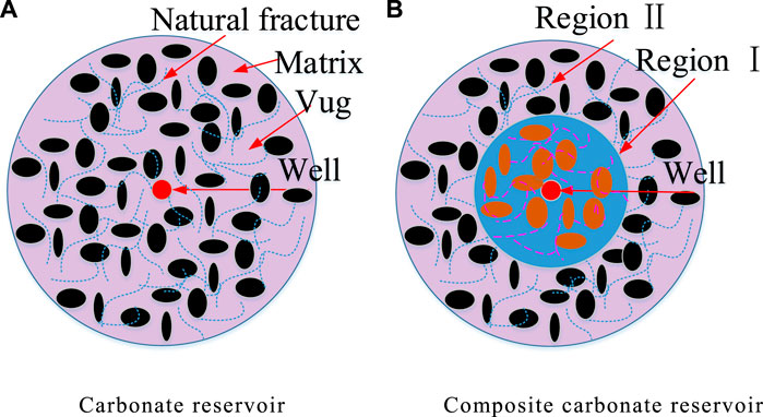
FIGURE 1. Schematic diagram of a carbonate reservoir. [(A) is Carbonate reservoir, (A) is Composite carbonate reservoir].
In 1960, Barenblatt et al. (1960) established a continuous medium seepage model for fractured reservoirs (Figures 2–a). In 1963, Warren and Root (1963) further clarified the concept of dual-medium seepage and related theories based on Barenblatt’s research. They believe that the fractured reservoirs are composed of uniformly distributed fracture systems and matrix systems (Figures 2–b). The fracture system has low porosity but strong seepage ability, which provides the main seepage channel for fluids. The matrix system has high porosity but low permeability, providing the main storage space for fluids. There is a quasi-steady interporosity flow between the matrix system and the fracture system, and the interporosity flow is proportional to the pressure difference between the two adjacent systems. In 1969, Kazemi (1969) proposed a dual-medium model similar to that of Warren and Root (Figures 2–c), which also assumed that all fluids in the reservoir flow into the wellbore through fractures. The difference is that this model equates the natural fractures in the reservoir with parallel fractures and divides the impermeable boundary artificially. The unsteady one-dimensional seepage between the matrix and fracture was solved by a numerical method. In 1975, Closmann (1975) first proposed the triple-medium model (Figures 2–d), which assumes that the reservoir consists of two sets of matrix systems and one set of fracture systems. One set of matrix systems has good physical properties, and the other set of matrix systems has poor physical properties. There is quasi-steady interporosity flow between the two matrix systems and the fracture system, respectively, but there is no interporosity flow between the matrix systems. All fluids in the reservoir flow into the wellbore through the fracture system. In 1982, Pruess and Narasimhan (1982a) believed that the dual-medium model was insufficient to describe the heterogeneity of fractured reservoirs and proposed the “multiple interacting continuous” (MINC) model (Figures 2–e). This model divides the matrix system into several continuous subunits (region 1, region 2, … , region n), and the fracture units are interconnected to form seepage channels. There is an unsteady interporosity flow between the matrix system and the fracture system. If the matrix system is regarded as a single continuum, the MINC model becomes the dual-medium model of Warren and Root. In 1983, Wu and Ge (1983) established a triple-medium seepage model for fractured-vuggy reservoirs based on Closmann’s idea. The model assumes that the reservoir is composed of three media, namely, the karst cave, fracture, and matrix, which are uniformly distributed. The karst cave and matrix have quasi-steady interporosity flow with the fractures, respectively. There is no interporosity flow between the cave and the matrix, and all fluid in the wellbore comes from the fractures. In 1986, Abdassah established a triple-medium seepage model for natural fractured reservoirs. In this model, the matrix system has impermeable boundaries. It is assumed that the reservoir consists of two sets of matrix systems and one set of fracture systems (similar to Closmann’s model). Different from Closmann’s model, Abdassah’s model assumes an unsteady one-dimensional flow between the matrix and the fracture. In 1993, Mao Bai (1993) established the seepage model of a porous and multi-permeability natural fracture reservoir considering the deformation of rock skeleton. The model considers all the factors and is solved by finite element, but the calculation process is relatively complex. In 2002, Camacho-Velázquez et al. (2002) established the seepage model of a fractured-vuggy reservoir by considering the mutual crossflow (the interporosity flow process is quasi-steady-state) between the karst cave, fracture, and matrix. The biggest difference between this model and the aforementioned triple-medium reservoir seepage model is that it not only considers the fracture system to supply fluid to the wellbore but also considers the karst cave to supply fluid to the wellbore. Liu et al. (2003), Wu et al. (2004), and Wu et al. (2006) established a fractured-vuggy reservoir seepage model by considering the interporosity flow between the karst cave, fracture, and matrix (the interporosity flow process is quasi-steady-state). In 2006, Kang et al. (2006) established a three-phase oil–gas–water seepage model in fractured-vuggy reservoirs considering the different distribution positions of the karst cave, fracture, and matrix. In 2012, Guo et al. (2012) established the seepage model of fractured-vuggy carbonate horizontal wells. The model assumes that the fluid in the oil well is supplied by the fractures and matrix, and the physical schematic diagram of three holes and double permeability is shown in Figures 2–f. In 2016, Gao et al. (2016) established a reservoir seepage model with oil wells drilled on large karst caves. The model divides the fractured-vuggy reservoir into two parts: the inner area is filled with karst caves, and the outer area is the fractured reservoir. The inner flow is non-Darcy flow, and the outer flow is dual-medium flow. In 2018, Wang et al. (2018) established a fractured vertical well seepage model for fractured-vuggy reservoirs after acidification. The model assumes that the reservoir consists of an internal acidified region and an external unacidified region. The interior is described by Darcy’s seepage flow, and the exterior is described by the triple-medium model. In 2019, Du et al. (2019) established a reservoir seepage model containing large karst caves. The model also divides the reservoir area into two parts; the interior is a large cylindrical cave (only considering the vertical flow of liquid in the cave), and the exterior is described by a triple-medium model. In 2020, Shi et al. (2020) established the seepage model of an upper and lower composite reservoir with a single medium inside and a double medium outside in order to solve the seepage problem after the acidification of multi-layer carbonate reservoirs. In 2022, Fernandes et al. (2022) considered the stress sensitivity of fractures and established the seepage model of fractured wells in upper and lower composite reservoirs.
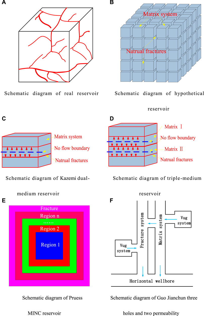
FIGURE 2. Schematic diagram of a dual-medium reservoir. [(A) is Schematic diagram of real reservoir, (B) is Schematic diagram of hypothetical, (C) is Schematic diagram of Kazemi dual-medium reservoir, (D) is Schematic diagram of triple-medium reservoir, (E) is Schematic diagram of Pruess MINC reservoir, (F) is Schematic diagram of Guo Jianchun three holes and two permeability].
The discrete medium model is often used to characterize large caverns in reservoirs. The fluid movement in the karst cave is usually described by the Navier–Stokes (N–S) equation, and the fluid in the porous medium is described by Darcy seepage. The difficulty of the discrete medium model is in solving the N–S equation and Darcy’s formula in coupling at the karst cave–porous medium interface (Figure 3). For this problem, there are two main methods in the literature now: one is the single-domain approach (SDA), established by Brinkman (1947) (Figures 3–b). The other is the two-domain approach (TDA), established by Beavers and Joseph (1967) (Figures 3–c). In 1967, Beavers and Joseph (1967) proposed a semi-empirical formula to couple the N–S equation and the Darcy equation, namely, the famous B–J velocity slip condition, on the basis of experimental results and theoretical analysis. In 1971, Saffman (1971) pointed out that the B–J condition was only applicable to models similar to the Beavers–Joseph experimental device. He proposed a more general boundary condition, namely, the Beavers–Joseph–Saffman (B–J–S) condition. In 1973, Jones (1973) studied the problem of fluid passing through a hollow sphere at a low Reynolds number, and the research object is divided into three regions: region I and III are described by the N–S equation, and region II is a porous medium region described by the Darcy formula. The B–J slip boundary condition is satisfied at the interface of the region. In 1994, Salinger et al. (1994) studied the single-domain and two-domain methods, respectively, and found that the two-domain method has higher computational accuracy and speed than the single-domain method. In 2004 and 2006, Arbogast et al. (2004) and Arbogast et al. (2006) used B–J boundary conditions to establish a coupling model to describe the seepage flow in fractured-vuggy reservoirs. The simulation results showed that large karst caves could be regarded as having infinite conductivity. In 2007, Peng Xiaolong extended the B–J–S boundary condition to an oil–water two-phase flow and established an oil–water two-phase flow model for fractured-vuggy reservoirs. In 2009, he used the streamlined method to solve an oil–water two-phase flow model of a fractured-vuggy reservoir considering discrete karst caves. In 2010, Yao Jun et al. (2010) showed fractures and caverns and established the seepage model of fractured and cavernous reservoirs by assuming Darcy seepage in the matrix and fractures and free flow in caverns. In 2018, Wan et al. (2018) believed that the size of the karst caves in Tarim Oilfield was large, often several meters or even tens of meters, so the karst caves have a great impact on seepage. The model assumes that the karst cave has been filled with a porous medium. Darcy seepage is used to simulate the karst cave and the reservoir area. On this basis, reservoir seepage models at different locations of oil wells were established (Figure 4). In 2019, Wu et al. (2019) combined the advantages of the discrete medium model and the continuous medium model to establish the seepage model of a fractured-vuggy reservoir using the boundary element method. The model assumes that large fractures and karst caves are described by the discrete medium model, and other regions are described by the triple continuous medium model. In the same year, Hallack et al. (2019) established a discrete model of an oil–water two-phase fractured-vuggy reservoir using the single-domain method. In 2020, Wan et al. (2020) improved on their work from 2018. The fluid flow in the unfilled cave is described by the N–S equation, the fluid flow in the matrix is described by Darcy’s seepage equation, and the interface between the karst cave and the matrix is described by the B–J condition. In the same year, Zhang et al. (2020) established a fractured-vuggy reservoir seepage model based on the discrete fractured-vuggy model, considering the influence of formation thermal conductivity. The model assumes that free flow in karst cave is described by the N–S equation, fracture flow is described by cubic law, and matrix seepage is described by the Darcy formula. The flow between the porous medium and the karst cave is coupled by the improved B–J–S equation. Many other scholars have also studied free flow and porous medium seepage in fractured-vuggy reservoirs (Popov et al., 2007; He et al., 2015).
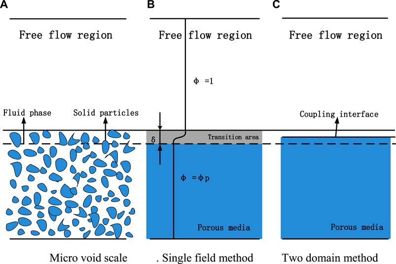
FIGURE 3. Schematic diagram of different interface coupling methods. [(A) is Micro void scale, (B) is Single field method, (C) is Two domain method].
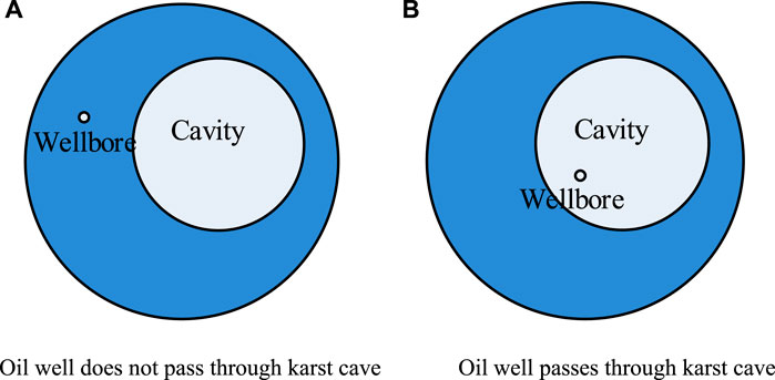
FIGURE 4. Schematic diagram of the Wan Yizhao physical model. [(A) is Oil well does not pass through karst cave, (B) is Oil well passes through karst cave].
The research achievements of many scholars have greatly promoted the development of the continuous medium and discrete medium models. The application conditions of the two types of models are different: the discrete medium model is used when the geometric size of cracks and caves is large and the heterogeneity is strong, the modeling of the discrete medium model requires more data, and the modeling process is complicated. The continuum model is suitable for weakly heterogeneous reservoirs, which is convenient for modeling and is widely used in well test analysis. It can be seen from the literature review that few scholars have studied the seepage law of composite triple-medium reservoirs (the physical model is shown in Figures 1–a). This paper focuses on the study of the continuum model. Using the methods of source function, Laplace transform, perturbation transform, and linear superposition principle of partial differential equation, a three-dimensional seepage model of vertical wells in a carbonate composite reservoir is established, which expands the application range of source function and provides a theoretical basis for well test analysis of carbonate composite reservoirs.
In this paper, the source function theory is used to establish the mathematical model of vertical well seepage in a composite carbonate reservoir; it first introduces point source function inner boundary conditions.
A carbonate reservoir is assumed to be a triple-medium reservoir with a point source that is infinitesimally small on the reservoir scale and sufficiently large on the micro-scale. At the moment of t=0, the amount of flow of
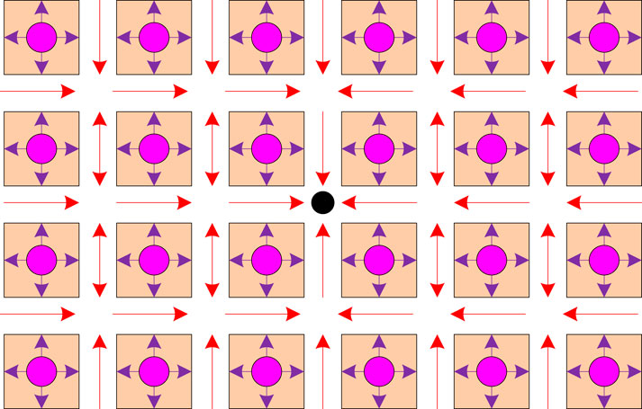
FIGURE 5. Schematic of seepage flow of a point source in an infinite triple-medium reservoir.  represents the matrix rock block;
  represents the karst cave;
  represents the fluid flow in the matrix system and cavern system;
  represents the flow in the fracture system; and
  represents the point source at any position in the infinite triple-medium reservoir.
It is assumed that the flow out of the point source at the moment of t=0 is
The flow of formation fluid flowing into the point source near this point is equal to the outflow
According to the properties of Dirac function
Equation 3 is the internal boundary condition of the point source function.
Model assumptions:
a. The matrix system and karst cave system are the main storage space, and the fracture system is the main flow channel. All production from the well comes from the influx of the fracture system, and the physical model of the composite reservoir is shown in Figures 1–b.
b. Considering the permeability sensitivity of a natural fracture system, it is assumed that the stress sensitivity coefficients inside and outside the complex reservoir are equal, and the permeability of the matrix system and cave system is constant.
c. The initial pressure of the reservoir is pi, and the temperature is constant during production.
d. The reservoir is a single-phase micro-compressible fluid, ignoring the effects of gravity and capillary force.
The seepage continuity equation of the fracture system, karst cave system, and matrix system in the inner region is shown as follows (Wu Yushu):
Similarly, the seepage continuity equation of the fracture system, karst cave system, and matrix system in the outer region is shown as Equation 5:
Considering the stress sensitivity of the natural fracture system, the permeability of natural fractures in the inner and outer regions can be expressed as follows:
The initial conditions of the inner and outer regions are as follows:
Assuming that the upper and lower boundaries of the composite reservoir are closed, three different outer boundary conditions are considered, infinite, constant pressure, and closed outer boundary, as shown in in the following equation:
The inner boundary conditions are shown as follows:
From the dimensionless parameters in Supplementary Appendix A, inner region continuity Eq. 4 is obtained dimensionless:
Similarly, outer region continuity Eq. 5 is obtained dimensionless:
In Eq. 12,
The dimensionless continuity of Eq. 11 in the inner region can be further simplified as in Laplace space as follows:
In Eq. 13,
Similarly, dimensionless continuity Eq. 12 in the outer region can be further simplified as in Laplace space as follows:
In Eq. 14,
Equations 13 and 14 are nonlinear partial differential equations, which are linearized by perturbation transformation as follows:
Because permeability modulus is often small, scholars generally believe that the zero-order perturbation solution can fully meet the needs of engineering calculation. The perturbation solution of order 0 is substituted into Eq. 13 and Eq. 14, respectively, and simplified as follows:
Equations 16 and 17 are of the same type of partial differential equations. Many scholars have studied these equations and given solutions under different external boundary conditions. However, no scholars have solved the two equations at the same time under different external boundary conditions. In this paper, the process of solving the two aforementioned equations simultaneously is given in detail in Supplementary Appendix B. Because the oil well is in the inner region, only the solution of the inner region seepage equation is given here.
Equation 18 is the solution of the point source function of the composite triple-medium reservoir. See Supplementary Appendix B for the specific expressions of A and Bn. The vertical well seepage equation of the composite reservoir can be obtained by integrating Eq. 18 on the z-axis direction, the horizontal well seepage equation of the composite reservoir can be obtained by integrating on the x-axis, and the fracturing well seepage equation can be obtained by integrating on the x-axis first and then on the z-axis. This paper mainly studies the vertical well seepage model of a composite triple-medium reservoir. Therefore, by integrating the point source function of Eq. 18 on the z-axis direction, the vertical well seepage equation is obtained as follows:
Defining dimensionless variables
The numerical inversion of Stehfest (1970) is used to convert the Laplace space solution of Eq. 20 into the time space solution, and the result is substituted into Eq. 15 to obtain the bottom hole pressure considering the effect of stress sensitivity. The bottom hole pressure calculated earlier does not take into account the effects of wellbore storage and skin coefficient. Using the Duhamel principle (Yao and Ai-fen, 1999), dimensionless wellbore storage coefficient CD and total skin coefficient S are introduced to obtain the relationship between the pressure solutions of vertical wells in Laplace space, as shown in the following equation:
There is no equation completely consistent with the model established in this paper in the known literature. Therefore, in order to test the correctness of the model established in this paper, it is necessary to assume that the physical properties of the inner and outer triple-medium reservoirs are the same. In this way, the composite reservoir can be regarded as a triple-medium reservoir and verified by Wu Yushu’s model. Reservoir parameters are shown in Table 1. The calculation results are shown in Figure 6. It can be seen that the model built in this paper is completely consistent with the model built by Wu Yushu, which proves the correctness of the model built in this paper.
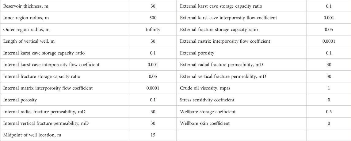
TABLE 1. Data used for the two models.
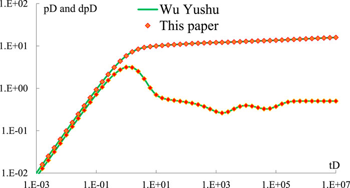
FIGURE 6. Comparison of model calculation results.
It is assumed that the oil well in the center of the composite triple-medium reservoir produces at a fixed rate, and the basic data of the reservoir are shown in Table 2. The bottom hole dimensionless pressure and dimensionless derivative pressure are plotted in the double logarithmic coordinate system, as shown in Figure 7.
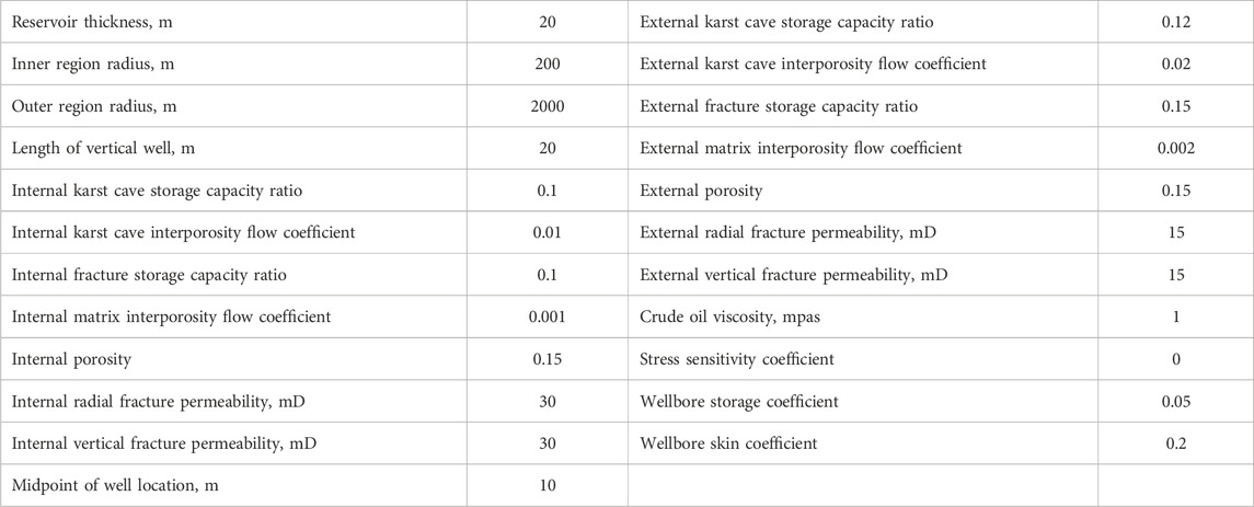
TABLE 2. Summary of reservoir parameters.
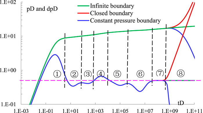
FIGURE 7. Vertical well seepage stage divisions of composite carbonate rock.
It can be seen from Figure 7 that vertical wells in composite reservoirs can be divided into eight seepage stages. ① Wellbore storage stage: the fluid used in this stage is only the part stored in the wellbore after shut-in, and the duration is usually very short; ② internal karst cave interporosity flow stage: with the propagation of bottom hole pressure drop in the formation, the fluid in the fracture system is gradually extracted. Because interporosity flow to the fracture is easy in the cave, the replenishment of the liquid in the cave leads to the slow growth of the pressure drop. However, with the gradual production of the liquid in the cave in the inner region, the growth of the pressure drop gradually increases, showing a “groove” feature on the derivative curve of the pressure drop; ③ matrix interporosity flow stage in the inner region: with the production of liquid in the cave, the pressure drop affects the matrix system. The replenishment of the fluid in the matrix system makes the drop of the derivative of pressure drop slow, but with the gradual production of the fluid in the matrix system in the inner region, the derivative of pressure drop gradually increases, which also shows the “groove” feature of first decreasing and then increasing; ④ transition flow stage in the inner and outer regions: the pressure drop spreads to the boundary of the inner and outer regions. Due to the permeability variation in the outer region, the pressure drop growth rate increases, and the derivative curve of the pressure drop shows a “hump-like” bulge; ⑤, ⑥ the stages of external karst cave interporosity flow and external matrix interporosity flow, respectively; the seepage mechanism of this stage is the same as that of internal karst cave interporosity flow ② and the internal matrix interporosity flow ③ and will not be repeated; ⑦ the radial flow stage of the reservoir, sometimes called quasi-steady-state seepage, in which the pressure drop growth rate of the reservoir tends to be stable. The dimensionless pressure drop derivative is a straight line with a value of 0.5; and ⑧ boundary flow stage: the pressure drop propagates to the reservoir boundary. The model established in this paper can simulate three types of outer boundary: closed boundary, infinite boundary, and constant-pressure boundary. The dimensionless derivative curve of pressure drop shows an up-warping curve with a slope of 1, a horizontal curve with a value of 0.5, and a descending curve, respectively.
Other parameters of the reservoir remain unchanged, as shown in Table 2. When the internal karst cave storage capacity ratio of the composite reservoir is 0.05, 0.15, and 0.2, respectively, the well test curve is as shown in Figure 8. It can be seen from the figure that the storage capacity ratio of the internal karst caves mainly affects the seepage stage of the internal karst caves and has little impact on other seepage stages. With the increase in the internal karst cave storage capacity ratio, the “groove” depth on the well test curve becomes deeper and deeper and the “groove” duration becomes longer and longer. The main reason is that with the increase in the storage capacity ratio of the internal karst cave, more liquid can be supplied by the karst cave, which effectively replenishes the formation energy, because of which the deeper the “groove” on the pressure drop derivative when the pressure drop propagates to the internal karst cave, the longer the action time is.
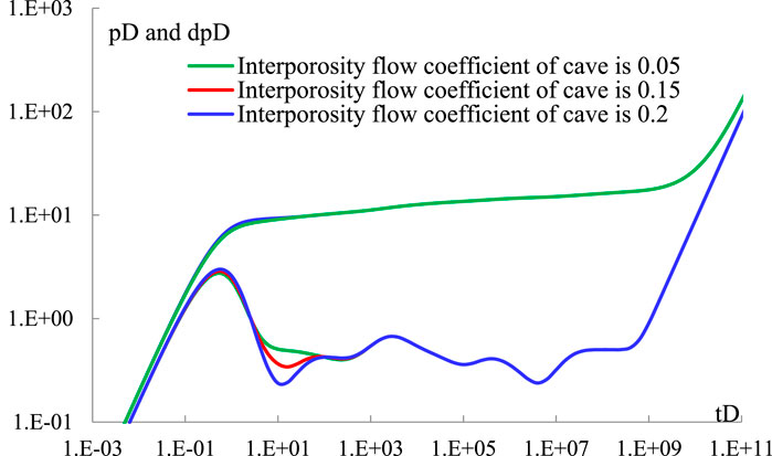
FIGURE 8. Sensitivity analysis of internal karst cave storage capacity ratio.
Other parameters of the reservoir remain unchanged, as shown in Table 2. When the coefficient ratio of the internal karst cave interporosity flow is 0.05, 0.01, and 0.003, respectively, the well test curve is as shown in Figure 9. It can be seen from the figure that the coefficient of the internal karst cave interporosity flow mainly affects the time when the internal karst cave interporosity flow stage occurs and has little influence on other seepage stages. With the increase in the interporosity flow coefficient of the internal karst cave, the interporosity flow between the karst cave and the fracture occurs easily. The earlier the interporosity flow occurs in the internal karst cave, the more left the position of the first “groove” on the dimensionless pressure drop derivative curve.
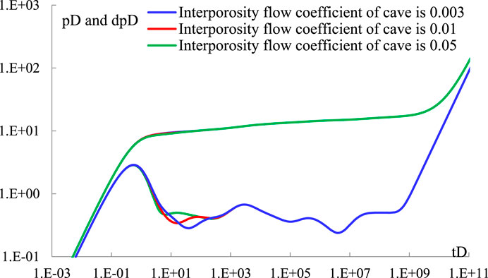
FIGURE 9. Sensitivity analysis of internal karst cave interporosity flow coefficient.
Other parameters of the reservoir remain unchanged, as shown in Table 2. When the fracture storage capacity ratio in the inner region of the composite reservoir is 0.1, 0.05, and 0.005, respectively, the well test curve is as shown in Figure 10. It can be seen from the figure that the internal fracture storage capacity ratio mainly affects the internal karst cave interporosity flow stage and matrix interporosity flow stage. As the sum of matrix storage capacity ratio, fracture storage capacity ratio, and karst cave storage capacity ratio is 1, when the fracture storage capacity ratio increases, the matrix storage capacity ratio and the karst cave storage capacity ratio decrease accordingly. Therefore, the depth and duration of the “grooves” of the karst cave interporosity flow phase and matrix interporosity flow phase become shallower and shorter.
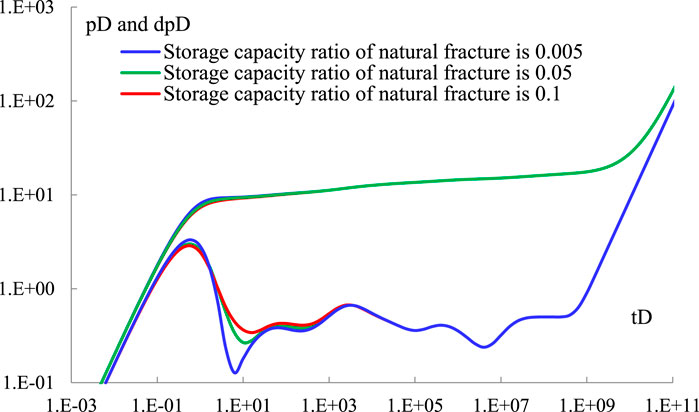
FIGURE 10. Sensitivity analysis of internal fracture storage capacity ratio.
Other parameters of the reservoir remain unchanged, as shown in Table 2. When the internal matrix interporosity flow coefficients of the composite reservoir are 0.002, 0.001, and 0.0005, respectively, the well test curve is as shown in Figure 11. It can be seen from Figure 11 that the matrix interporosity flow coefficient in the inner zone mainly affects the time when the matrix interporosity flow stage occurs in the inner zone and has little effect on other seepage stages. With the increase in the matrix interporosity flow coefficient in the inner zone, the interporosity flow between the matrix and the fracture is more likely to occur. The earlier the matrix crossflow occurs in the inner region, the more leftward the position of the second “groove” on the dimensionless pressure drop derivative curve. Since the influence of the parameters of the cavern system, fracture system, and matrix system on the seepage law of oil wells in the outer area is similar to that in the inner area, the analysis is not repeated here.

FIGURE 11. Sensitivity analysis of internal matrix interporosity flow.
Other parameters of the reservoir remain unchanged, as shown in Table 2. When the ratio of inner permeability to outer permeability of the composite reservoir is 3, 1, and 1/3, respectively, the well test curve is as shown in Figure 12. It can be seen from Figure 12 that the permeability ratio of the inner and outer regions mainly affects the transition flow stage of the inner and outer regions and the later seepage stage of the reservoir. With the increase in the permeability ratio in the inner and outer regions, the “hump”-shaped bulge in the transition flow stage becomes smaller, and the reservoir boundary flow stage occurs later. The main reason for this phenomenon is that with the increase in the permeability of the internal reservoir, the liquid supply capacity of the internal reservoir increases.
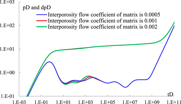
FIGURE 12. Sensitivity analysis of internal and external permeability ratio.
Other parameters of the reservoir remain unchanged, as shown in Table 2. When the inner radius of the composite reservoir is 1,000 m, 600 m, and 200 m, respectively, the well test curve is as shown in Figure 13. It can be seen from Figure 13 that the inner radius mainly affects the seepage law of the inner region reservoir. With the increase in the inner radius, the duration of the karst cave interporosity flow and the matrix interporosity flow in the inner region increases slightly, and the transition flow in the inner and outer regions is delayed.
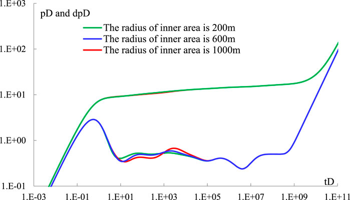
FIGURE 13. Sensitivity analysis of inner radius.
Other parameters of the reservoir remain unchanged, as shown in Table 2. When the outer radius of the composite reservoir is 3,000 m, 2,500 m, and 2,000 m, respectively, the well test curve is as shown in Figure 14. It can be seen from Figure 14 that the outer radius mainly affects the later seepage law of the outer reservoir. With the increase in the outer radius, the reservoir boundary flow appears later. On the contrary, when the reservoir boundary flow occurs earlier, it conceals the seepage characteristics of other seepage stages.
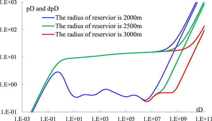
FIGURE 14. Sensitivity analysis of outer reservoir radius.
Other parameters of the reservoir remain unchanged, as shown in Table 2. When the wellbore storage coefficients are 5, 0.5, and 0.05, respectively, the well test curve is as shown in Figure 15. It can be seen from Figure 15 that the wellbore storage coefficient mainly affects the seepage law of the internal reservoir. With the increase in the wellbore storage coefficient, the seepage stage of wellbore storage lasts longer, which conceals the seepage characteristics of the internal karst cave interporosity flow and matrix interporosity flow stage.
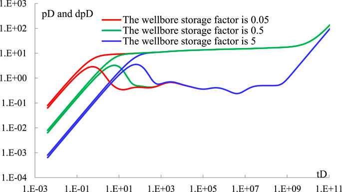
FIGURE 15. Sensitivity analysis of wellbore storage coefficient.
Other parameters of the reservoir remain unchanged, as shown in Table 2. When the wellbore skin factors are 5, 2, and 0, respectively, the well test curve is as shown in Figure 16. It can be seen from Figure 16 that the wellbore skin factor mainly affects the seepage law of the oil well in the wellbore storage stage. With the increase in the skin factor in the wellbore, the dimensionless pressure drop derivative has a larger “hump” shape at the wellbore storage stage, and the dimensionless pressure is greater.
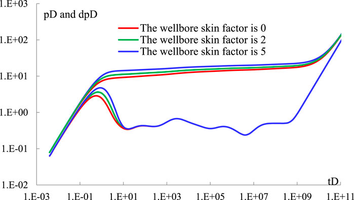
FIGURE 16. Sensitivity analysis of wellbore skin factor.
Other parameters of the reservoir remain unchanged, as shown in Table 2. When the vertical well lengths are 30 m, 15 m, and 3 m, respectively, the well test curve is as shown in Figure 17. It can be seen from Figure 17 that the length of the vertical well only has an impact on the early seepage law and has little impact on other seepage stages. With the decrease in the length of the straight section, the dimensionless pressure drop increases, and the derivative curve of the dimensionless pressure drop in the early stage gradually presents a straight line with a slope of −1. This phenomenon indicates that spherical flow occurs in the reservoir.
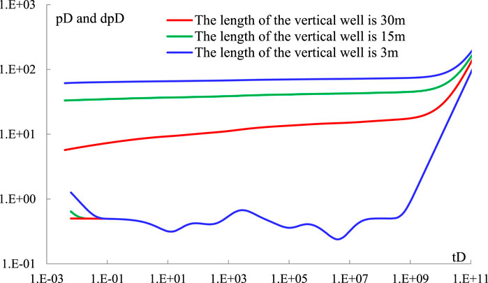
FIGURE 17. Sensitivity analysis of vertical well length.
Other parameters of the reservoir remain unchanged, as shown in Table 2. When the stress sensitivity of the fracture system is 0.04, 0.01, and 0, respectively, the well test curve is as shown in Figure 18. It can be seen from Figure 18 that stress sensitivity has a great influence on oil well seepage. With the increase in stress sensitivity coefficient, the dimensionless pressure drop and its derivative gradually increase.
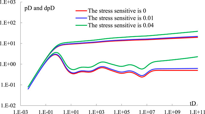
FIGURE 18. Stress sensitivity analysis.
Carbonate reservoirs are well developed in western China. Well A in Northwest Oilfield suffered well leakage during the drilling of the reservoir, resulting in pollution near the well. Therefore, acid plugging removal was carried out in well A, and a pressure recovery test was carried out after the operation was completed. The model built in this paper was used to fit the well test data, as shown in Figure 19. It can be seen from the figure that the physical property of the reservoir near the well was improved after acidification, and the well test curve showed the first groove ①. The groove represents the karst interporosity flow in the inner region; according to the model calculation, the storage capacity ratio of the inner karst cave is 0.12, and the permeability of the inner region is 58 mD. The radius of the inner zone is 34.4 m, and the pressure drop quickly spreads to the outer zone. Affected by the transition flow from the inner zone to the outer zone, the fracture interporosity flow stage in the inner zone is not obvious. Groove ② and groove ③ represent the outer cave interporosity flow and the fracture interporosity flow, respectively; the storage capacity ratio of the outer cave is 0.05, and the storage capacity ratio of the outer fracture is 0.02. The permeability of the outer region was 46 mD, and the acidizing operation improved the physical properties of the inner region to a certain extent.
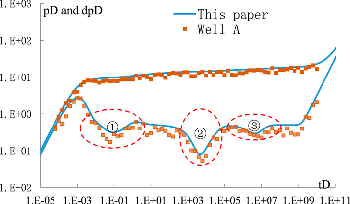
FIGURE 19. Fitting comparison diagram of the well test data.
In this paper, the vertical well seepage model of a triple-medium composite reservoir is established using the methods of point source function, Laplace transform, perturbation transform, and partial differential equation superposition principle. The following understandings and conclusions are obtained in the research process:
(1) The continuity equations (after perturbation transformation), boundary conditions, and initial conditions of the inner and outer regions of a composite triple-medium reservoir are linear equations that meet the linear superposition principle of partial differential equations. Based on the Ozkan source function, the composite triple-medium point source function is obtained using the linear superposition principle, and then, the vertical well seepage model of a composite reservoir is established.
(2) The vertical well seepage of the composite triple-medium reservoir can be divided into eight seepage stages: ① the wellbore storage stage, ②internal karst cave interporosity flow stage, ③ internal Matrix interporosity flow stage, ④ transition flow stage in inner and outer regions, ⑤ external karst cave interporosity flow stage, ⑥ external matrix interporosity flow stage, ⑦ radial flow stage of the reservoir, and ⑧ boundary flow stage.
(3) The matrix/karst cave storage capacity ratio mainly affects the depth of the “groove” on the pressure drop derivative curve, and the matrix/karst cave interporosity flow coefficient mainly affects the time when the “groove” appears on the pressure drop derivative curve.
(4) With the increase in permeability ratio in the inner and outer regions, the “hump”-shaped bulge in the transition flow stage becomes smaller and smaller, and the reservoir boundary flow stage occurs later.
(5) A well in Northwest Oilfield was explained successfully by the model established in this paper, which provides theoretical guidance for well test analysis and the application of composite triple-medium reservoirs.
The original contributions presented in the study are included in the article/Supplementary Material; further inquiries can be directed to the corresponding author.
QZ: writing–original draft. CM: writing–review and editing and writing–original draft. CJ: writing–review and editing. HJ: writing–review and editing. MX: writing–review and editing. JS: writing–review and editing: ZC: writing–review and editing.
The authors declare financial support was received for the research, authorship, and/or publication of this article. This work was funded by the National Natural Science Foundation of China (grant nos. 51804258, 51974255, and 52274007), the Natural Science Basic Research Program of Shaanxi Province (grant no. 2023-JC-YB-414), and the Youth Innovation Team of Shaanxi Universities Scientific Research Program Funded by the Shaanxi Provincial Education Department (program no. 22JS029).
The authors declare that the research was conducted in the absence of any commercial or financial relationships that could be construed as a potential conflict of interest.
All claims expressed in this article are solely those of the authors and do not necessarily represent those of their affiliated organizations, or those of the publisher, the editors, and the reviewers. Any product that may be evaluated in this article, or claim that may be made by its manufacturer, is not guaranteed or endorsed by the publisher.
The Supplementary material for this article can be found online at: https://www.frontiersin.org/articles/10.3389/feart.2023.1276567/full#supplementary-material
Abadassah, D., and Ershaghi, I. (1986). Triple-porosity systems for representing naturally fractured reservoirs. SPE Form. Eval. 1 (2), 113–127. doi:10.2118/13409-pa
Arbogast, T., and Lehr, H. L. (2006). Homogenization of a Darcy–Stokes system modeling vuggy porous media. Comput. Geosci. 10 (3), 291–302. doi:10.1007/s10596-006-9024-8
Arbogast, T, Brunson, D S, Bryant, S L, et al. (2004). A preliminary computational investigation of a macro-model for vuggy porous medium. Dev. Water Sci. 55, 267–278.
Bai, M., Elsworth, D., and Roegiers, J. (1993). Multiporosity/multipermeability approach to the simulation of naturally fractured reservoirs. Water Resour. 29 (6), 1621–1633. doi:10.1029/92wr02746
Barenblatt, G. L., Zheltov Iu, P., and Kochina, I. N. (1960). Basic concepts in the theory of seepage of homogeneous liquids in fissured rocks. PMM 24 (5), 852–864.
Beavers, G. S., and Joseph, D. D. (1967). Boundary conditions at a naturally permeable wall. J. Fluid Mech. 30 (1), 197–207. doi:10.1017/s0022112067001375
Brinkman, H. (1947). A calculation of the viscous force exerted by a flowing fluid on a denseswarm of particles. Appl. Sci. Res. Al 1, 27–34. doi:10.1007/bf02120313
Camacho-Velázquez, R., Vásquez-CruzCastrejón-Aivar, M. R., and Arana-Ortiz, V. (2002). Pressure-transient and decline-curve behavior in naturally fractured vuggy carbonate reservoirs. SPE Reserv. Eval. Eng. 8 (2), 95–111. doi:10.2118/77689-pa
Du, X., and Lu, D. (2019). A novel analytical well test model for fractured vuggy carbonate reservoirs considering the coupling between oil flow and wave propagation. J. Petroleum Sci. Eng. 173, 447–461. doi:10.1016/j.petrol.2018.09.077
Fernandes, F. B., Braga, A. M. B., Souza, A. L. S. d., et al. (2022). Analytical model to effective permeability loss monitoring in hydraulically fractured oil wells in pressure-sensitive reservoirs. J. Petroleum Sci. Eng., doi:10.1016/j.petrol.2022.111248
Gao, B, Huang, Z. Q, Yao, J, Lv, X. R., and Wu, Y. S. (2016). Pressure transient analysis of a well penetrating a filled cavity in naturally fractured carbonate reservoirs. J. Petroleum Sci. Eng. 145, 392–403. doi:10.1016/j.petrol.2016.05.037
Guo, J. C., Nie, R. S., and Jia, Y. L. (2012). Dual permeability flow behavior for modeling horizontal well production in fractured-vuggy carbonate reservoirs. J. Hydrology 464 (465), 281–293. doi:10.1016/j.jhydrol.2012.07.021
Hallack, D. M. C., de Araujo Cavalcante Filho, J. S., and Couto, P. (2019). “Implementation of a two-phase simulator based on the Brinkman’s equation for vuggy-karstified reservoirs,” in Proceedings of the Offshore Technology Conference Brasil 2019, Rio de Janeiro, Brazil, October 2019. doi:10.4043/29776-ms
He, J., Killough, J. E., Fadlelmula, F. M. M., and Fraim, M. (2015). “Unified finite difference modeling of transient flow in naturally fractured carbonate karst reservoirs - a 3D case study,” in Proceedings of the SPE Annual Technical Conference and Exhibition, Houston, Texas, USA, September, 2015, 5420–5431. doi:10.2118/175098-ms
Jones, I. P. (1973). Low Reynolds number flow past a porous spherical shell. Math. Proc. Camb. Philosophical Soc. 73 (1), 231–238. doi:10.1017/S0305004100047642
KangWu, Z. Y. S., LiWuZhang, J. Y. J., Wang, G., and Zhang, J. (2006). Modeling multiphase flow in naturally fractured vuggy petroleum reservoirs. Proc. - SPE Annu. Tech. Conf. Exhib. 3 (1), 1794–1803. doi:10.2118/102356-ms
Kazemi, H. (1969). Pressure transient analysis of naturally fractured reservoirs with uniform fracture distribution. Soc. Petrol Eng. J. 9 (4), 451–462. doi:10.2118/2156-a
Liu, J, Bodvarsson, G. S., and Wu, Y. S. (2003). Analysis of flow behavior in fractured lithophysal reservoirs. J. Contam. Hydrology 62 (63), 189–211. doi:10.1016/S0169-7722(02)00169-9
Ozkan, E, and Raghavan, R (1991). New solutions for well-test-analysis problems: part 1—analytical considerations. SPE EvalV6, N3 6, P359–P368. doi:10.2118/18615-pa
Peng, D. L., Qi, Z., Liang, B., and Liu, X. (2007). “A new Darcy-Stokes flow model for cavity-fractured reservoir,” in Proceedings of the 69th European Association of Geoscientists and Engineers Conference and Exhibition 2007: Securing The Future, London, UK, June 2007, 3356–3363. doi:10.2523/106751-ms
Peng, X, Du, Z, Liang, B., and Qi, Z. (2009). Darcy-Stokes streamline simulation for the Tahe-fractured reservoir with cavities. SPE J. 14 (3), 543–552. doi:10.2118/107314-pa
Popov, P., Qin, G., BiEfendiev, L. Y., Kang, Z., and Li, J. (2007). Multiphysics and multiscale methods for modeling fluid flow through naturally fractured carbonate karst reservoirs. SPE Reserv. Eval. Eng. 12 (2), 218–231. doi:10.2118/105378-PA
Pruess, K., and Narasimhan, T. N. (1982a). A practical method for modeling fluid and heat flow in fractured porous media. Soc. Petroleum Eng. J. 25 (1), 14–26. doi:10.2118/10509-pa
Pruess, K., and Narasimhan, T. N. (1982b). On fluid reserves and the production of superheated steam from fractured, vapor-dominated geothermal reservoirs. J. Geophys. Res. 87 (B11), 9329–9339. doi:10.1029/JB087iB11p09329
Ren, Z, Xiaodong, W, Dandan, L., Wei, G, Zhiming, C, Zhaoguang, T., et al. (2016). Semi-analytical model of the transient pressure behavior of complex fracture networks in tight oil reservoirs. J. Nat. Gas Sci. Eng. 35, 497–508. doi:10.1016/j.jngse.2016.09.006
Ren, Z, Xiaodong, W, Guoqing, H, Lingyan, L, Xiaojun, W., Xianwei, Z., et al. (2017). Transient pressure behavior of multi-stage fractured horizontal wells in stress-sensitive tight oil reservoirs. J. Petroleum Sci. Eng. 157, 1197–1208. doi:10.1016/j.petrol.2017.07.073
Ren, Z, Yan, R., Huang, X., Liu, W., Yuan, S., Qu, Z., et al. (2019). The transient pressure behavior model of multiple horizontal wells with complex fracture networks in tight oil reservoir. J. Petroleum Sci. Eng. 173, 650–665. doi:10.1016/j.petrol.2018.10.029
Saffman, P. G. (1971). On the boundary condition at the surface of a porous medium. Stud. Appl. Math. 50 (2), 93–101. doi:10.1002/sapm197150293
Salinger, A. G., Aris, R., and Derby, J. J. (1994). Finite element formulations for large scale, coupled flows in adjacent porous and open fluid domains. Int. J. Numer. Methods Fluids 18 (12), 1185–1209. doi:10.1002/fld.1650181205
Shi, W., Yao, Y., Cheng, S., and Shi, Z. (2020). Pressure transient analysis of acid fracturing stimulated well in multilayered fractured carbonate reservoirs: a field case in Western Sichuan Basin, China. J. Petroleum Sci. Eng. 184, 106462. doi:10.1016/j.petrol.2019.106462
Stehfest, H. (1970). Algorithm 368: numerical inversion of Laplace transforms [D5]. Commun. ACM 13 (1), 47–49. doi:10.1145/361953.361969
Wan, Y. Z., Liu, Y. W., Chen, F. F., Wu, N. Y., and Hu, G. W. (2018). Numerical well test model for caved carbonate reservoirs and its application in Tarim Basin, China. J. Petroleum Sci. Eng. 161 (41474119), 611–624. doi:10.1016/j.petrol.2017.12.013
Wan, Y., Liu, Y., and Wu, N. (2020). Numerical pressure transient analysis for unfilled-caved carbonate reservoirs based on Stokes-Darcy coupled theory. J. Petroleum Sci. Eng. 190, 107085. doi:10.1016/j.petrol.2020.107085
WangFanDongSongZhao, MZXHW., Xu, G., Song, H., and Xu, G. (2018). Analysis of flow behavior for acid fracturing wells in fractured-vuggy carbonate reservoirs. Math. Problems Eng. 2018, 1–20. doi:10.1155/2018/6431910
Warren, J. E., and Root, P. J. (1963). The behavior of naturally fractured reservoirs. Soc. Petroleum Eng. J. 3 (03), 245–255. doi:10.2118/426-pa
Wu, Y. S., and Ge, J. L. (1983). The transient flow in naturally fractured reservoirs with three-porosity systems. Acta, Mech. Sinica, Theor. Appl. Mech. 15 (1), 81–85.
Wu, Y. S., Liu, H. H., and Bodvarsson, G. S. (2004). A triple-continuum approach for modeling flow and transport processes in fractured rock. J. Contam. Hydrology 73 (1–4), 145–179. doi:10.1016/j.jconhyd.2004.01.002
Wu, Y. S., Qin, G., Ewing, R. E., Efendiev, Y., Kang, Z., and Ren, Y. (2006). A multiple-continuum approach for modeling multiphase flow in naturally fractured vuggy petroleum reservoirs. Int. Oil Gas Conf. Exhib. China 2006 - Sustain. Growth Oil Gas 2, 739–750. doi:10.2523/104173-ms
Wu, Y., Cheng, L., Huang, S., Jia, P., Fang, S., Wang, S., et al. (2018). “A semi-analytical model for simulating fluid flow in naturally fractured reservoirs with non-homogeneous vugs and fractures,” in Proceedings of the Offshore Technology Conference Asia, Kuala Lumpur, Malaysia, June 2018. doi:10.4043/28493-ms
Yao, J., and Ai-fen, L. I. (1999). General solutions for seepage flow in single porous medium. J. Hydrodynamics 14 (3), 317–324.
Yao, J., Huang, Z., and Li, Y. (2010). “Discrete fracture-vug network model for modeling fluid flow in fractured vuggy porous medium,” in Proceedings of the Society of Petroleum Engineers - International Oil and Gas Conference and Exhibition in China 2010, Beijing, China, June 2010, 320–333. doi:10.2118/130287-ms
Zhang, X., Huang, Z., Yao, J., Bi, Y., Li, Y., and Lei, Q. (2020). “Numerical modeling of heat extraction in hot fractured vuggy reservoir with thermal hydraulic mechanical coupling method based on discrete fracture-vug model,” in Proceedings of the 54th U.S. Rock Mechanics/Geomechanics Symposium, June, 2020.
Keywords: the point source function, vertical well seepage model, carbonate reservoir, triple-medium composite reservoir, sensitivity analysis
Citation: Minjing C, Zhan Q, Jiajun C, Junhang H, Xinggang M, Shuaihu J and Chenyu Z (2023) Study on the vertical well seepage model in composite carbonate reservoirs. Front. Earth Sci. 11:1276567. doi: 10.3389/feart.2023.1276567
Received: 12 August 2023; Accepted: 11 October 2023;
Published: 03 November 2023.
Edited by:
Madhavaraju Jayagopal, National Autonomous University of Mexico, MexicoReviewed by:
Wendong Wang, China University of Petroleum, ChinaCopyright © 2023 Minjing, Zhan, Jiajun, Junhang, Xinggang, Shuaihu and Chenyu. This is an open-access article distributed under the terms of the Creative Commons Attribution License (CC BY). The use, distribution or reproduction in other forums is permitted, provided the original author(s) and the copyright owner(s) are credited and that the original publication in this journal is cited, in accordance with accepted academic practice. No use, distribution or reproduction is permitted which does not comply with these terms.
*Correspondence: Qu Zhan, emhxdUB4c3l1LmVkdS5jbg==
Disclaimer: All claims expressed in this article are solely those of the authors and do not necessarily represent those of their affiliated organizations, or those of the publisher, the editors and the reviewers. Any product that may be evaluated in this article or claim that may be made by its manufacturer is not guaranteed or endorsed by the publisher.
Research integrity at Frontiers
Learn more about the work of our research integrity team to safeguard the quality of each article we publish.