 Yuxin Da
 Zhiyuan Ning2
 Jinhai Zhao
94% of researchers rate our articles as excellent or good
Learn more about the work of our research integrity team to safeguard the quality of each article we publish.
Find out more
ORIGINAL RESEARCH article
Front. Earth Sci. , 06 November 2023
Sec. Environmental Informatics and Remote Sensing
Volume 11 - 2023 | https://doi.org/10.3389/feart.2023.1273637
This article is part of the Research Topic Coal and Rock Dynamic Disasters: Advances of Physical and Numerical Simulation in Monitoring, Early Warning, and Prevention, volume II View all 29 articles
In view of the shortcomings of the traditional method of determining the position of the separation layer, according to the actual movement of the pressure balance arch and the rock layer in the overburden, the concept of the triangular separation domain is proposed, and the relationship between the range of the triangular separation domain and the mining distance and the mining fracture angle is established. The calculation method of rock load is modified. By analyzing the stress mode in the pressure arch of the separation zone, the mechanical model of the deflection calculation of each rock stratum is established. Combining the triangular separation zone with the new mechanical model, the calculation model of the dynamic evolution analysis of the separation zone and the calculation model of the composite beam in the separation zone are established. The traditional method and the improved method are used to determine the separation position in an actual mining example. The field exploration proves that the results of the improved method described in this paper are more accurate. The model predicts the position of overburden separation by comparing the deflection between adjacent strata on the same horizontal contact surface, and can accurately predict the position of separation above the working face.
In the process of coal seam mining, the overlying rock will deform, break, and form a large number of cracks (Liu et al., 2023a). The cracks that are pulled along the bedding direction between or within the rock layers are called separation cracks (referred to as separation). With the increase in coal mining depth, multi-seam mining, thick and extra-thick coal seam mining, the difference in engineering geological characteristics of overlying strata and complex hydrogeological conditions, the overlying bed separation water damage occurs from time to time and has the characteristics of large instantaneous water volume, periodicity, and no obvious signs of water inrush, which is extremely harmful (Wu et al., 2014). At present, there are a wide range of mines with separated layer water disasters, involving a complete range of coal measures, and there are differences in the formation conditions and influencing factors, causes, and intensity of water disasters in different coal mines (Liu et al., 2023b), which shows the complexity of the problem of separated layer water disasters. Therefore, accurate prediction of the development of the separation of the overlying strata is very essential for preventing and controlling the water inrush caused by these separations.
Many scholars have carried out relevant theoretical and practical research studies on the development of high separation layer and the water disaster of the separation layer. Ning et al. (2017) used digital photography and multi-position monitoring of boreholes to study rock movement and overburden failure caused by long-wall mining and proposed a statistical formula for predicting the maximum height of overburden failure in close-distance multi-seam mining. By analyzing the fracture of WKS in multi-seam mining, Ma et al. (2022) established a ‘long beam’ hydraulic model and calculated the fracture position of WKS in the Xiqu mine. Through the physical simulation of the water and sand gushing test system, Li et al. (2022) studied and explored the spatial distribution and dynamic evolution law of the mining overburden fracture zone under the coupling effect of stress and seepage. Based on the key stratum theory, Hu et al. (2021) used the plate theory to reveal the relationship between the fracture of the overlying strata and the influx of bed separation water. Shu et al. (2020) used the cusp catastrophe model to explain the energy transition mode of key layer breaking in the separation layer and proposed two water inrush modes of fracturing and splitting. Peng et al. (2019) comprehensively analyzed the mechanism of this type of disaster from the aspects of water channel, water filling source, material source, water storage space, power source, and geological structure in view of the water inrush and sand inrush accident in the Zhaojin Coal Mine of the Huanglong Coalfield. Through the discrete element particle flow PFC3D software, Shi (2020) simulated the possibility of water and sand inrush under different mining thicknesses under the condition of weakly cemented overburden. He et al. (2018) proposed a method for determining the contact state of rock strata based on the step-by-step comparison and merging method and proposed a mechanical model of stepped composite beams that can be used to study and calculate the dynamic evolution of separation. Fan et al. (2019), combined with the Winkler foundation beam model, established the mechanical model of water damage above the water-conducting fracture zone and derived the theoretical discriminant of the first and periodic water-conducting form separated layers. Chu (2013) put forward the prevention and control technology of water disaster according to the spatial development position, hydrogeological characteristics, and periodic weighting step of the working face in the Hongliu Coal Mine. Li et al. (2009) thought that the water filling source of the water inrush accident in S1818 and S1821 fully mechanized the mining face of Datong No. 1 Coal Mine was the separated layer water of the overlying strata. Taking the Beizao Coal Mine in Shandong Province as an example, Sun et al. (2012) studied the mechanism of roof separation and water inrush in soft rock strata. Wang et al. (2021) developed a new type of similar material to simulate strata separation. Combined with the evolution characteristics of acoustic emission events, Zhang et al. qualitatively and quantitatively discussed the influence of fracture degree on velocity dispersion characteristics (Zhang et al., 2023a) and established a quantitative relationship model between macroscopic mechanical properties and treatment temperature (Zhang et al., 2023b). PALCHIK (2003) located bed separation in the overburden strata, revealed the influence of coal seam thickness, separation development position, overburden thickness and other factors on horizontal fractures, and studied the mechanical properties of upper and lower strata in the bed separation space. Zhou et al. (2023) revealed the internal mechanism of rock mass watering to inhibit rock burst and carried out a series of uniaxial compression tests on sandstone samples with different water contents. Cai et al. (2023) verified by the uniaxial compression test that the localization of compressive stress dominates the macroscopic failure of pre-holed rock. Other scholars have carried out research on the determination of overburden failure height (PALCHIK, 2015) and longwall mining speeds (Zhang et al., 2021). The aforementioned research study has played a positive role in understanding the movement law of mining overburden, the evolution process of bed separation, and the prediction of bed separation position.
However, the current determination of the separation position is mostly based on the traditional separation position determination formula (Yue et al., 2015; Yan et al., 2018) or its derived formula through macro analysis (Liang and Sun, 2002; Yang et al., 2014; Ji et al., 2022) or empirical approximation (Qiao et al., 2014; Yan et al., 2016). However, the traditional composite beam theory ignores the influence of the rock strata outside the calculation range on the rock strata within the calculation range. It neither judges in advance which range of rock strata can be used as composite beams nor considers the essence of the deformation of the separated rock strata under the action of the horizontal stress and gravity stress as a whole. Only the more common longitudinal superposition model is analyzed, and the results obtained are often inconsistent with the actual separation position. Therefore, in view of the characteristics of the abscission zone in the overlying strata of the goaf, the author simplifies the abscission zone pressure arch into a triangular abscission zone. At the same time, for the composite beam in the abscission zone, considering the influence of the horizontal in situ stress of deep mining, the rock beam load solution model is established according to the mechanical model of the rock deflection calculation and the geometric relationship of the deformation of the composite beam. Finally, it is applied to the judgment of the abscission position in the field.
The study area is the 22207 fully mechanized mining face in the Shendong mining area of China (Figure 1). The designed strike length of the working face is 4544.7 m, the recoverable strike length is 4538 m, the buried depth is 285.2–398.8 m, the average is 363.6 m, the coal thickness is 2.8–6.6 m, the average is 4.82 m, and the average dip angle is 1–3°. The coal-bearing strata in the field are the Middle–Lower Jurassic Yan‘an Formation, and the sedimentary basement of the coal measures is the Upper Triassic Yanchang Formation. The Yan‘an Formation in the area is intact and has not been eroded later. The thickness of the coal-bearing strata is 157.34 (B99 Borehole)−325.06 m (B107 Borehole) with an average of 212.48 m.
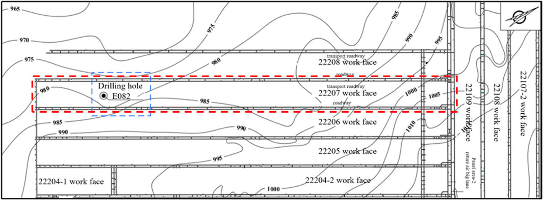
FIGURE 1. Burtai mine mining engineering plan (22,207 working face surrounding).
The coal-bearing strata in the field are the Middle–Lower Jurassic Yan’an Formation, and the sedimentary basement of the coal measures is the Upper Triassic extension group. According to the lithology, lithofacies combination characteristics, and coal-bearing characteristics of the formation, the coalfield can be divided into three rock sections. The three rock sections are divided into one rock section (J1-2y1 + 2), two rock sections (J1-2y3), and three rock sections (K1I-Q) (Table 1). The Yan’an Formation in the area is well preserved and has not been eroded in the later stage. The lithology of the three rock sections is mainly composed of gray–white, deep gray, gray–black medium-fine-grained sandstone, siltstone, sandy mudstone, mudstone, and coal seam, which is easy to deform. Due to the uneven settlement of the overlying strata in the process of coal mining, the separation space is often formed in the second and third rock sections. The water accumulation in these separations leads to frequent catastrophic water inrush accidents. Therefore, it is necessary to further optimize the separation identification method based on the existing separation identification method to prevent similar roof water inrush events after the mining of the 22,207 working face.
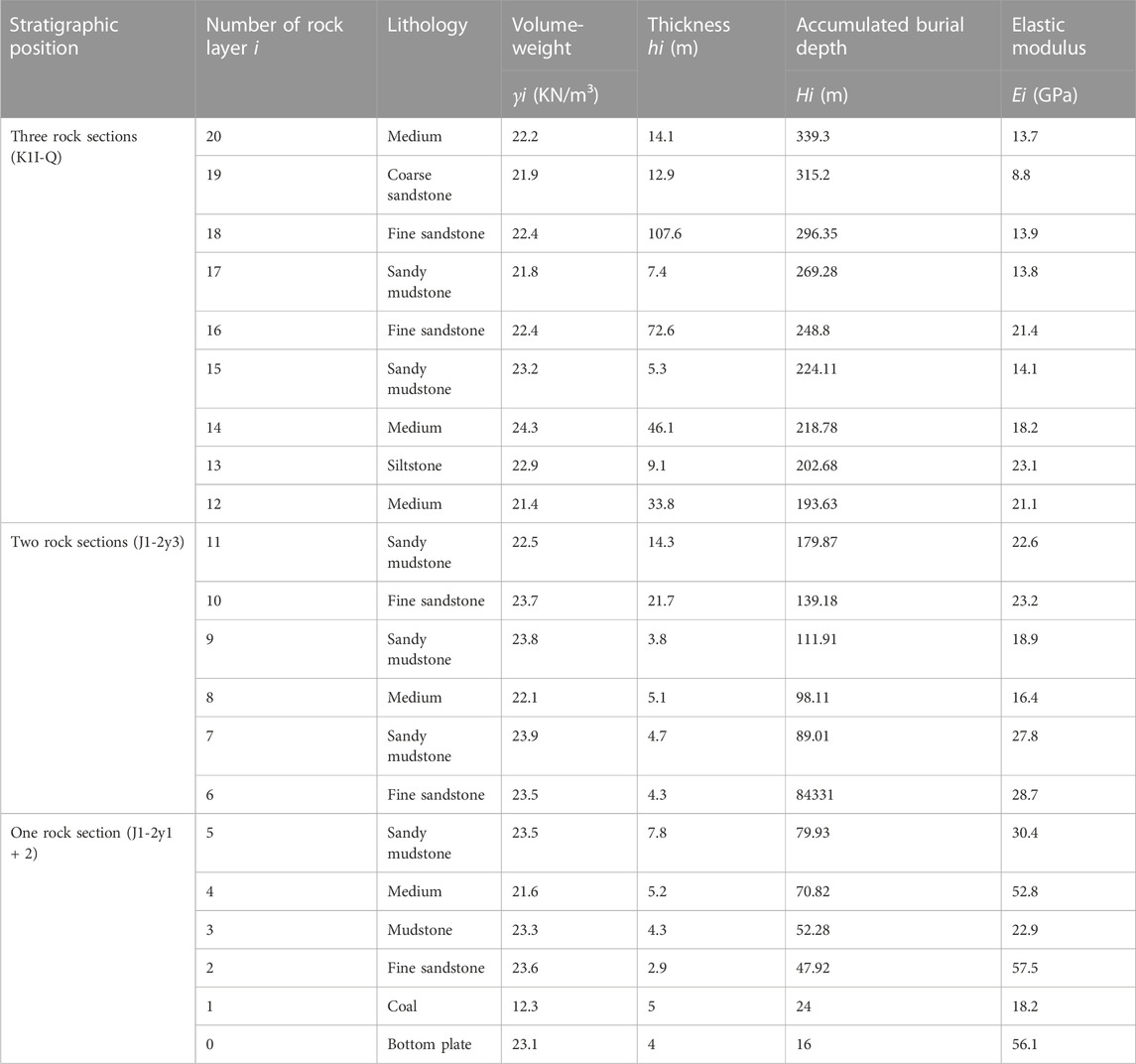
TABLE 1. Formation characteristics and rock mechanics parameters of the 22,207 mining face.
For any size of the goaf, there is a pressure balance arch in the overlying strata above it (Figure 2). The load of the rock strata outside the balance arch is transmitted to the arch foot by the balance arch without affecting the rock strata in the balance arch. The rock strata in the balance arch will bend and sink under the action of self-weight due to the loss of support. When the subsidence of adjacent rock strata is not balanced, it will separate from the contact surface of rock strata and form separation. Therefore, the area of the balanced arch is the area that forms the separation layer, which is called the separation layer domain. In the vertical direction, the separation layer cannot be formed in the whole overburden rock. The span of the separation layer at the same position in the horizontal direction is not fixed. The load borne by the upper strata of the separation layer under different footage conditions is not fixed. With the continuous expansion of the goaf area, the old and small balance arches are destroyed, and new and large balance arches will be generated. The front foot of the arch moves forward with the increase in the mining footage, and the range of the arch is also expanding. With the progress of this process, the separation area is also expanding, and the roof separation of the stope is also dynamically developed in the horizontal and vertical directions of the working face. Therefore, when calculating the development of bed separation in roof overburden under a certain mining size, the range and shape of the bed separation domain should be determined first.
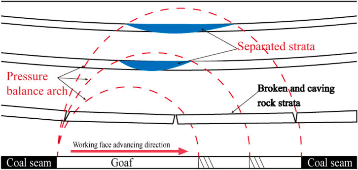
FIGURE 2. Mechanical structure of overburden bed separation.
Influenced by many factors such as buried depth, mining thickness and lithology, the shape equation of the balanced arch is very complex and not easy to apply. Combined with the similar material simulation experiment and numerical simulation experiment observation results of some scholars (Figure 3), it is found that only the rock layer between the two rock fracture lines (red diagonal in the following figure) will bend, sink, and produce separation due to the loss of support. Based on this, it is proposed that the triangular area trapped by two rock fracture lines and the coal seam roof can be approximately used as the separation zone (that is, the range trapped by two red oblique lines and one green horizontal line in the following diagram). This not only takes into account the fact that the separation domain exists and the general morphological characteristics of the separation domain but also reduces the computational difficulty and enhances the operability.
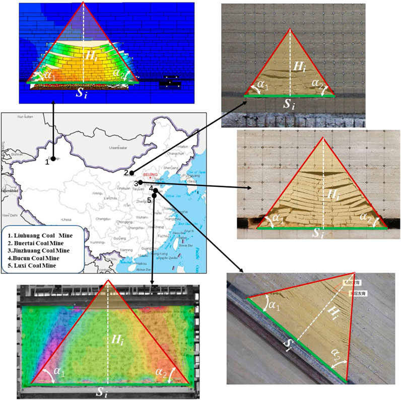
FIGURE 3. Multiple tests to simulate the deformation and failure process of overburden rock.
According to the geometric shape of the development of the separation domain, it can be known that the advancing distance of the working face (
According Xu et al. (2018), the fracture shape of the rock stratum is symmetrical, and the fracture angle of the rock stratum on the side of the open-off cut and working face is basically equal. According to the calculation formula of the fracture angle of the key stratum,
where
The value range of the two bottom angles of the triangular off-layer domain is generally 40°–80°. This relationship can quickly determine the size of the separation zone of the overlying strata in the goaf. In order to better describe the problem, default
In addition to its own weight, the load of any rock stratum in the mining overburden is also usually affected by the interaction of the overlying adjacent rock strata. Generally speaking, the load of mining strata is non-uniformly distributed, but for practical engineering problems, in order to be convenient and simple, it is usually assumed that the rock load is uniformly distributed. In order to modify the calculation method of mining overburden rock load, the conventional calculation method of rock load is briefly described here.
The calculation model of the composite rock beam is shown in Figure 4. There are n rock layers above the immediate roof, and the thickness of each rock layer is

FIGURE 4. Composite beam theory research layer schematic diagram.
According to the mechanics of materials, the curvature of each rock beam is
By using the condition that the curvature
Because the section of each rock stratum is a rectangle, the moment of inertia
Equations 5 and (6) can be combined to obtain
The essence of using the key stratum theory to determine the location of bed separation development is the comparison between the bending stiffness
When calculating the fracture distance of the upper strata of the separation layer, the calculation range should be delineated in advance, and the calculation range is the range of the strata that apply load to the upper strata of the separation layer. The traditional calculation method does not take into account the change in the actual load, and the default actual load is still the original ground stress. In fact, due to the existence of the pressure balance arch after excavation, the range of rock strata that can apply load to the upper strata of the separation layer is limited and variable. Only the rock strata in the pressure balance arch (Figure 5A) apply load to the upper strata of the separation layer. After determining the scope and shape of the abscission zone in the overburden under a certain footage condition, in order to facilitate the calculation and analysis, it is assumed that the calculation range is a triangular abscission zone, and the length of the suspension span of each rock layer involved in the calculation is different and the rock span decreases from bottom to top. At the same time, the calculation process must be carried out on the premise that no rock layers in the abscission zone are broken. Because the breaking of rock strata is developed from bottom to top, it is generally only necessary to ensure that the bottom strata are not broken. If the lower strata in the separation domain are broken, the calculation object only includes the upper unbroken strata in the separation domain. The simplified overlying strata model is shown in Figure 5B.

FIGURE 5. Distribution form of overburden rock in the pressure arch.
In the triangular separation domain, the rock strata involved in the calculation are no longer assumed to be of equal span, and the actual span of each rock stratum is determined by the thickness of the rock stratum and the height of the rock stratum in the separation domain. The core problem is to calculate the curvature (or bending moment) of each rock stratum in its middle position. However, due to the unequal span of each rock stratum, the actual load range of each rock stratum will change, and the relevant calculation formula will be adjusted.
When the rock beam is sinking and bending, the fracture length of the rock beam in different layers is different, and the fracture length of the upper rock beam is smaller. Clearly, the curvature of the rock beam breaking bending is larger and the radius of curvature is smaller. It can be considered that the curvature of the rock beam breaking increases with the decrease in the length of the rock beam. This way, the curvature of the rock beam after mining should be related to the buried depth of the rock layer in addition to its internal force-bending moment and bending stiffness. The triangular relationship can be established by the rock breaking angle α, the buried depth of the rock layer, and the breaking length of the rock beam, as shown in Figure 6:
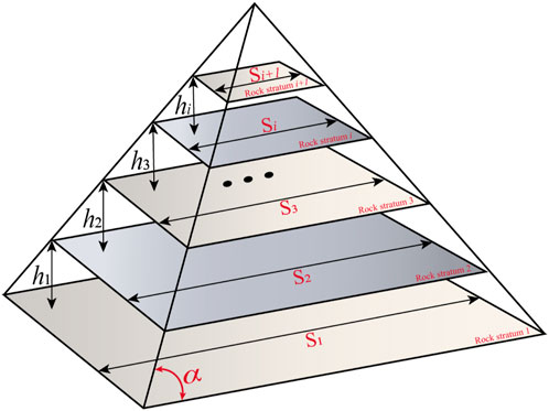
FIGURE 6. Variable curvature rock load calculation model.
The ratio of the curvature of each rock layer to the first layer can be expressed as
where
Equations 8, 9, and 12 can be combined to obtain
The lower the rock stratum is, the larger the length of the rock beam is, and the more load will be shared accordingly. In fact, by comparison, it can also be seen that under the same conditions, the old top load obtained by modified Eq. 13 is smaller than that of conventional Eqs. 8, 9.
The influence of the horizontal stress field on the separation of overlying strata and roof instability in goaf has been confirmed in mines in Australia, Britain, the United States, China, New Zealand, and Japan (Kang et al., 2010). Therefore, the theoretical model used to calculate and predict the separation position of overlying strata should consider the comprehensive influence of vertical stress and horizontal stress, as shown in Figure 7. Among them,
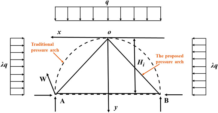
FIGURE 7. Stress analysis of the pressure arch.
On the basis of the aforementioned analysis, we select one layer of the overlying strata to calculate the deflection and maximum tensile stress under the combined action of vertical and horizontal stress, as shown in Figure 8: the maximum deflection occurs in the middle of the rock beam, where
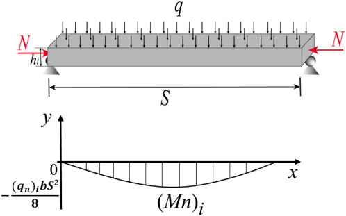
FIGURE 8. Mechanical model of a single-layer rock simply supported beam.
The position where the maximum tensile stress appears is also the position where the bending moment is the largest. The calculation formula of the maximum tensile stress is as follows:
Then, for the overlying multilayer rock strata, combined with Eq. 13, the mid-span deflection of the ith-layer rock beam and its corresponding bending moment can be obtained as
Through this formula, the deflection of each rock stratum can be calculated. When the deflection of the ith layer is less than that of the i-1th layer, that is
This method combines the knowledge of the triangular separation domain, traditional composite beam principle, lateral pressure theory, and maximum deflection calculation of a simply supported beam to create a calculation model that can be used for dynamic evolution analysis of the separation layer. It not only calculates the influence of rock strata outside the range on the rock strata within the calculation range but also determines in advance which rock strata can be used as composite beams. Considering the essence of deformation of separated rock strata under the action of horizontal stress and self-weight stress as a whole, it overcomes the limitations of traditional methods that only analyze common longitudinal superposition models.
By comparing the maximum deflection of rock strata, the actual combination state of rock strata can be presented, which makes the contact state of rock strata (whether there is separation between adjacent rock strata) easy to operate. Therefore, the improved separation position discrimination method is more in line with the actual situation.
In order to show the use method of the correction formula and to compare the accuracy of the discrimination results of the improved and traditional methods, the traditional and improved methods are used to discriminate the position of the overburden separation layer in the 22207 working face (Figure 9) of the Shendong Buertai Coal Mine. The relative accuracy of the two methods is assessed by comparing the predicted locations of separated strata from the two methods with field measurements.
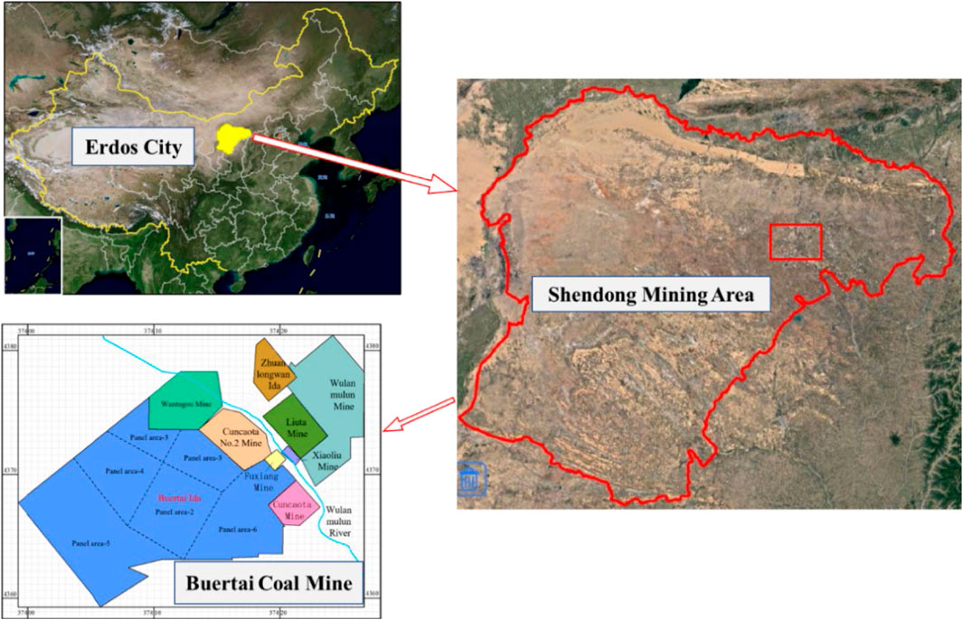
FIGURE 9. Site location map: Buertai Coal Mine.
The overlying strata have uneven settlement due to mining damage, and the caving zone, fracture zone, and bending subsidence zone are formed from the bottom up. Caving and fracture zones are commonly referred to as water flowing fractured zones (Figure 10). The degree of rock fragmentation in the caving zone is high; the degree of rock mass fragmentation in the fracture zone is small, forming a certain amount of rock cracks; the fracture distribution in the range of the bending subsidence zone is obviously different from that of the water-conducting fracture zone. It is difficult to accumulate a large amount of groundwater in the separation layer in the range of the water-conducting fracture zone, and the rock and soil structures in the bending subsidence zone are relatively complete. The integrity of the separation layer in this range is better, and it can better accumulate the separation layer water. The separation layer water forms a water-conducting channel through the load and eventually leads to the occurrence of the separation layer water inrush event. Therefore, this paper focuses on the separation space formed above the water-conducting fracture zone.
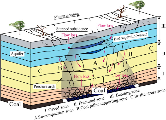
FIGURE 10. Post-mining overburden ‘three zone’ divisions.
According to the field operation of the Buertai Coal Mine in the Shendong mining area, the ratio of the height of the water flowing fractured zone to mining height (RFM) is 21, the mining height of the 22,207 working face is 5 m, and the development height of the water flowing fractured zone above the 22,207 working face is 105 m. Table 1 shows that the total thickness of the overburden rock in the 1–12 layers is 107.9 m, indicating that the water-conducting fracture has developed in the 12th layer. Therefore, the calculation of the separation space of 1–12 layers is meaningless. The following only needs to determine the separation position of the 12–20 layers of the overburden rock.
There are eight layers of overburden rock from the 12th layer to the 20th layer, so the value range of
When
When
The calculation steps of
When
The calculation results of
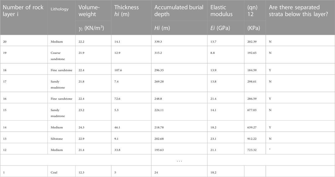
TABLE 2. Position determination results for separated strata in the 22,207 mining face using the traditional method.
According to Eq. 9, the conventional load
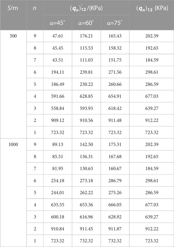
TABLE 3. Relationship between rock load, mining distance, and fracture angle.
Table 3 shows that when the rock mining breaking angle
The variation of rock load
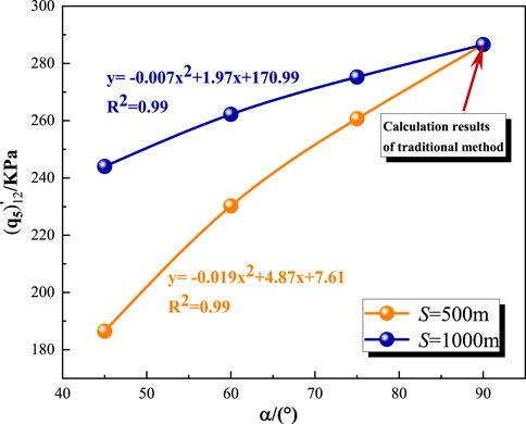
FIGURE 11. Curve of the modified load
Figure 4 and Table 2 show that the mining breaking angle
Because the settlement of the rock stratum occurs from bottom to top, the comparative analysis of rock beam deflection should also be carried out from bottom to top. Combined with Table 1 and Table 3, for the convenience of calculation, taking
Using the same calculation method, we calculate the deflection of each rock layer in the range of the separation zone, as shown in Table 4. The excessive deflection of the rock beam or the generation of the separation layer is mainly related to the softer and thinner rock layer, but the effective rock beam length and effective load involved in the deflection calculation in the range of the separation zone will make the generation of the separation layer more complicated. The relationship between the rock beam disturbances in the adjacent separation domain is

TABLE 4. 22,207 working face overlying strata deflection calculation results.

TABLE 5. Improved method was used to determine the separation position of the 22,207 stope.
Before the mining of the 22,207 working face, a borehole (E082) was installed at a distance of 93.4 m from the open-off cut position of the 22,207 working face. The drilling TV imaging observation (DTIO) was carried out after mining on 25 August 2020. The position of the separation layer can be determined by the fracture development at different depths shown by the drilling TV image. The borehole images of 145 m (the bottom of the 17th overburden), 210 m (the bottom of the 16th overburden), 270 m (the middle of the 13th overburden), and 310 m (the bottom of the 12th overburden) are shown in Figure 12.
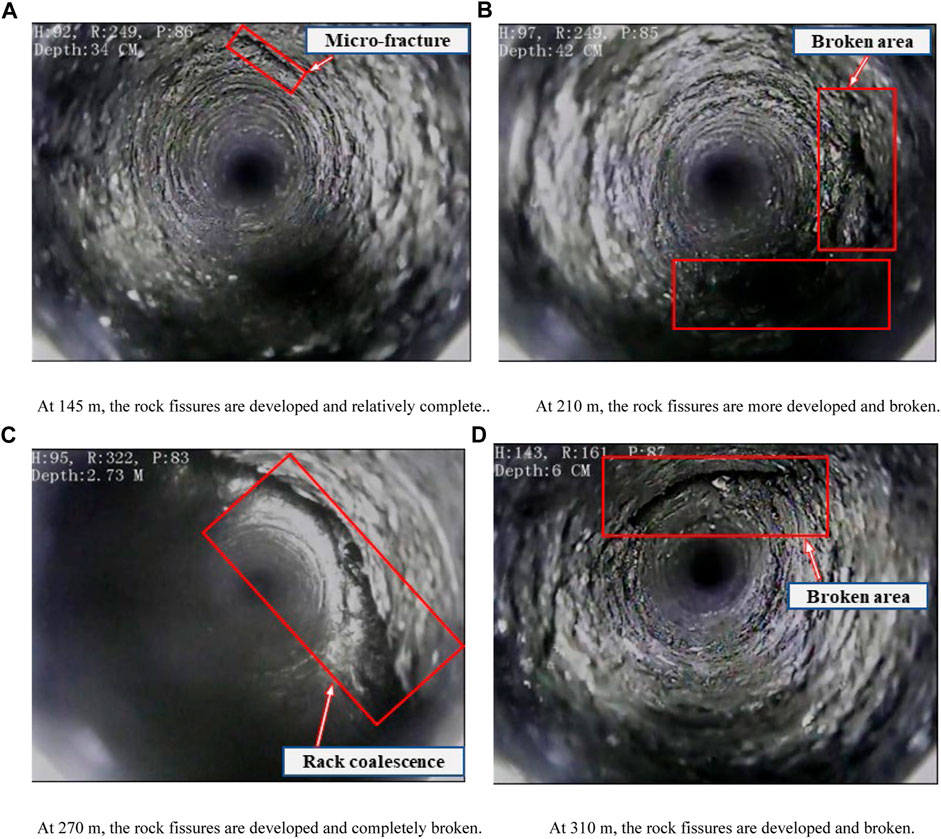
FIGURE 12. Borehole TV images of different depths in the 22,207 working face.
Figure 12A shows that between the 16th and 17th layers, although the cracks have developed to this height, the rock layer is still relatively complete, and there is no separation. Figure 12B shows that the fractures between the 16th and 15th layers are relatively broken, and the separation layer appears. Figure 12C shows that the overlying strata in the middle of the 13th layer are completely broken, and the contact surface between the 14th layer and the 13th layer has a large horizontal fracture, including the separation space caused by uneven settlement. In Figure 12D, the horizontal fracture has developed to the bottom of the 12th layer, but the rock layer has only small cracks and still maintains a complete block structure, probably because the 11th layer is sandy mudstone (Table 1). Sandy mudstone is a soft rock that can withstand greater deformation without fracturing and softens after saturation, so the cracks can be partially refilled.
In summary, there is no separation space between the 17th and 18th layers, but the separation occurred between the 13th and 14th layers, the 15th and 16th layers, and the 11th and lower layers are completely broken.
These observations are different from the results of the traditional separation layer calculation method described in Section 4.1.1 because the traditional method does not consider the influence of the separation layer on the load of the traditional composite beam overburden when calculating the load of the composite beam overburden between the 17th and 18th layers. The distribution of bed separation in the overlying strata measured on the site is in good agreement with the distribution of bed separation identified by the improved method (Section 4.1.3), which indicates that the results of the improved method are more accurate than those of the traditional method for the strata deeply affected by complex geological conditions, as shown in Table 6.
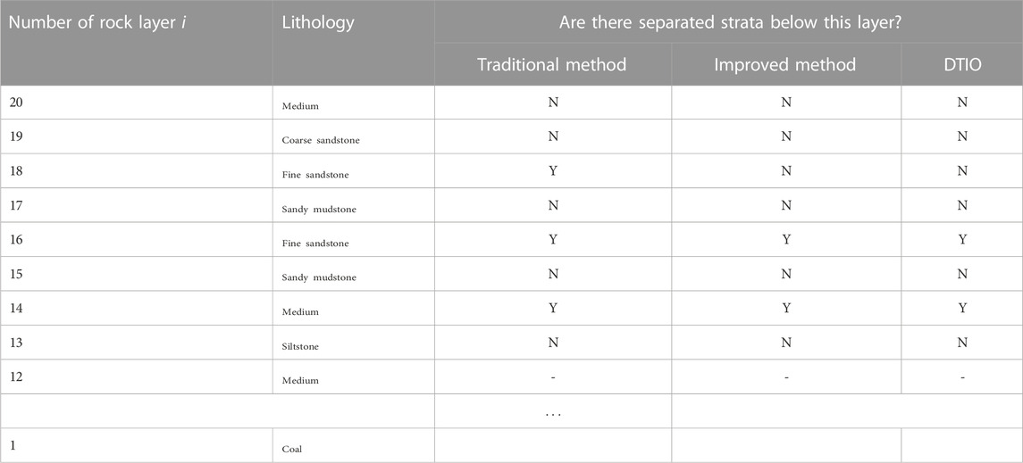
TABLE 6. Comparison of different methods to determine the position of stratification in the 22207 working face.
1) In view of the traditional method, there is no influence of rock strata outside the calculation range on the rock strata within the calculation range, and there is no limitation of judging which rock strata can be used as composite beams in advance. According to the actual movement of rock strata and the concept of triangular-separation domain, considering the linear change in the curvature of the rock beam instead of constant value, the modified calculation formula of corresponding rock strata load is established, and the influence of mining distance and fracture angle of mining overburden on rock strata load is calculated and analyzed.
2) Considering the nature of the deformation of the separated strata under the action of horizontal stress and self-weight stress, combined with the knowledge of the triangular separation domain, traditional composite beam principle, lateral pressure theory, and maximum deflection calculation of simply supported beams, a mechanical calculation model for comparing the maximum deflection of the rock strata is proposed. It overcomes the limitation of the traditional method that only analyzes the more common longitudinal superposition model, can present the actual combination state of the rock strata, and more accurately determine the location of any separated strata.
3) A calculation model based on the comparative analysis of the maximum deflection of rock strata is established. The field exploration results show that the improved method has more accurate calculation results, which provides effective theoretical support for the prevention and control of roof water inrush caused by water accumulation in bed separation space and has practical engineering value.
The original contributions presented in the study are included in the article/Supplementary Material; further inquiries can be directed to the corresponding author.
YD: methodology, writing–original draft, and writing–review and editing. ZN: writing–original draft, data curation, methodology. ZH: writing–review and editing, formal analysis, validation. QD: writing–review and editing, formal analysis, funding acquisition, software. QL: funding acquisition, writing–original draft, and writing–review and editing. JZ: writing–review and editing. QL: writing–review and editing.
The authors declare that financial support was received for the research, authorship, and/or publication of this article. This work was supported by the National Natural Science Foundation of China (Project No. 51904168), the Anhui Province Key Laboratory of Building Structure and Underground Engineering (KLBSUE-2022-07), and the Scientific Research Foundation of Key Laboratory of Mining Disaster Prevention and Control (MDPC202012).
The authors would like to express their gratitude to everyone who helped with the present study.
The authors declare that the research was conducted in the absence of any commercial or financial relationships that could be construed as a potential conflict of interest.
All claims expressed in this article are solely those of the authors and do not necessarily represent those of their affiliated organizations, or those of the publisher, the editors, and the reviewers. Any product that may be evaluated in this article, or claim that may be made by its manufacturer, is not guaranteed or endorsed by the publisher.
Cai, X., Yuan, J. F., Zhou, Z. L., Pi, Z., Tan, L., Wang, P., et al. (2023). Effects of hole shape on mechanical behavior and fracturing mechanism of rock: implications for instability of underground openings. Tunn. Undergr. Space Technol. 141, 105361. doi:10.1016/j.tust.2023.105361
Chu, Y. D. (2013). Analysis of roof sandstone water bursting mechanism in Hongliu coalmine, yuanyanghu mining area, eastern ningxia. Coal Geol. China 25 (4), 34–39. doi:10.3969/j.issn.1674-1803.2013.04.09
Fan, K. F., Li, W., Wang, Q., Liu, S., Xue, S., Xie, C., et al. (2019). Formation mechanism and prediction method of water inrush from separated layers within coal seam mining: a case study in the Shilawusu mining area, China. Eng. Fail. Anal. 103, 158–172. doi:10.1016/j.engfailanal.2019.04.057
He, J. H., Li, W., Liu, Y., Yang, Z., Liu, S. L., and Li, L. F. (2018). An improved method for determining the position of overlying separated strata in mining. Eng. Fail. Anal. 83, 17–29. doi:10.1016/j.engfailanal.2017.09.015
Hu, R., Wu, J. W., Zhai, X., and Liu, W. (2021). Recognition and prevention of bed separation water: based on trapezoid platform model. Geofluids 2021, 1–10. doi:10.1155/2021/6626268
Ji, J. S., Li, Z. H., Yang, K., Zhou, G., Ma, G., Liu, C., et al. (2022). Research on formation mechanism and evolution pattern of bed separation zone during repeated mining in multiple coal seams. Geofluids 2022, 1–19. doi:10.1155/2022/4290063
Kang, H., Zhang, X., Si, L., Wu, Y., and Gao, F. (2010). In-situ stress measurements and stress distribution characteristics in underground coal mines in China. Eng. Geol. 116, 333–345. doi:10.1016/j.enggeo.2010.09.015
Li, W. B., Wu, P., and Wang, X. J. (2009). Probe into gently dipping strata roof separation water jeopardizing on fully mechanized mining face and controlling. Coal Geol. China 21 (10), 42–45. doi:10.3969/j.issn.1674-1803.2009.10.012
Li, Y., Zhang, S., Yang, Y., Chen, H., Li, Z., and Ma, Q. (2022). Study on the water bursting law and spatial distribution of fractures of mining overlying strata in weakly cemented strata in West China. Geomechanics Eng. 28 (6), 613–624. doi:10.12989/gae.2022.28.6.613
Liang, Y., and Sun, D. (2002). Study on the composed rock beam theory of strata movement and its application. Chin. J. Rock Mech. Eng. 21, 654–657. doi:10.3321/j.issn:1000-6915.2002.05.010
Liu, S. M., Sun, H. T., Zhang, D., Yang, K., Wang, D., Li, X., et al. (2023a). Nuclear magnetic resonance study on the influence of liquid nitrogen cold soaking on the pore structure of different coals. Phys. Fluids 35 (1). doi:10.1063/5.0135290
Liu, S. M., Sun, H. T., Zhang, D. M., Yang, K., Li, X., Wang, D., et al. (2023b). Experimental study of effect of liquid nitrogen cold soaking on coal pore structure and fractal characteristics. J. Energy 275 (7), 127470. doi:10.1016/j.energy.2023.127470
Ma, K., Yang, T. H., Zhao, Y., Hou, X., Liu, Y., Hou, J., et al. (2022). Mechanical model for analyzing the water-resisting key stratum to evaluate water inrush from goaf in roof. Geomechanics Eng. 28 (3), 299–311. doi:10.12989/gae.2022.28.3.299
Ning, J. G., Wang, J., Tan, Y., Zhang, L., and Bu, T. (2017). In situ investigations into mining-induced overburden failures in close multiple-seam longwall mining: a case study. J], Geomechanics Eng. 12 (4), 657–673. doi:10.12989/gae.2017.12.4.657
Palchik, V. (2003). Formation of fractured zones in overburden due to longwall mining. Environ. Goel 44 (1), 28–38. doi:10.1007/s00254-002-0732-7
Palchik, V. (2015). Bulking factors and extents of caved zones in weathered overburden of shallow abandoned underground workings. Int. J. Rock Mech. Min. Sci. 79, 227–240. doi:10.1016/j.ijrmms.2015.07.005
Peng, T., Feng, X. H., and Liang-liang, L. (2019). Study on mechanism of water inrush and sand inrush in mining of coal seam with thick overlying bedrock. Coal Sci. Technol. 47 (7), 260–264. doi:10.13199/j.cnki.cst.2019.07.035
Qiao, W., Yang, H., Yuan, Z.-B., and Guo, W. (2014). Formation and prevention of water inrush from roof bed separation with full-mechanized caving mining of ultra thick coal seam. Chin. J. Rock Mech. Eng. 33, 2077–2084. doi:10.13722/j.cnki.jrme.2014.10.014
Shi, L. (2020). Numerical simulation study on law of water and sand in-rush in working face under condition of weakly cemented stratum. Coal Sci. Technol. 48 (7), 347–353. doi:10.13199/j.cnki.cst.2020.07.039
Shu, Z. Y., He, B. Q., and Ling, L. (2020). Study on mechanism of separation strata water-inrush induced by impact energy of key strata abrupt breaking. Coal Sci. Technol. 48 (5), 149–156. doi:10.13199/j.cnki.cst.2020.05.021
Sun, Z. F., Yan, S. J., and Wang, Y. Q. (2012). Primary investigation of water inrush from separation layer over mining face of soft rock stratum. Coal Sci. Technol. Mag. (3), 27–31. doi:10.19896/j.cnki.mtkj.2012.03.014
Wang, Z. Y., Zhang, Q., Shao, J., Zhang, W., Wu, X., and Zhu, X. (2021). New type of similar material for simulating the processes of water inrush from roof bed separation. ACS Omega 5 (47), 30405–30415. doi:10.1021/acsomega.0c03535
Wu, Q., Fan, Z. L., Zhang, Z., and Zhou, W. (2014). Evaluation and zoning of groundwater hazards in Pingshuo No. 1 underground coal mine, Shanxi Province, China, Shanxi Province. Hydrogeology J. 22 (7), 1693–1705. doi:10.1007/s10040-014-1138-9
Xu, B., Jin-quan, J., Jin, D., and Pengqiang, Z. (2018). Mechanical derivation and experimental simulation of fracture angle of overlying key strata in stope. J. China Coal Soc. 43 (03), 599–606. doi:10.13225/j.cnki.jccs.2017.1346
Yan, H., He, F.-l., Yang, T., Li, L., Zhang, S., and Zhang, J. (2016). The mechanism of bedding separation in roof strata overlying a roadway within a thick coal seam: a case study from the Pingshuo Coalfield, China. Eng. Fail. Anal. 62, 75–92. doi:10.1016/j.engfailanal.2015.12.006
Yan, H., Zhang, J. X., Li, L. y., Feng, R. m., and Li, T. T. (2018). Prediction of upper limit position of bedding separation overlying a coal roadway within an extra-thick coal seam. J. central south Univ. 25 (2), 448–460. doi:10.1007/s11771-018-3749-0
Yang, Q., Qiao, W., and Le, J. (2014). Analysis on formation condition of water in roof bed separation in fully mechanized face of extra-thick seam and evaluation of its risk. Min. Saf. Environ. Prot. 41, 64–66. doi:10.3969/j.issn.1008-4495.2014.03.018
Yue, J. G., Yang, W. F., and Gu, C. S. (2015). Formation mechanism and identification method of super-high seam by fully mechanized caving method. Environ. Goel 23, 603–610. (Suppl). doi:10.13544/j.cnki.jeg.2015.s1.092
Zhang, S. Z., Fan, G. W., Zhang, D., Li, S., Chen, M., Fan, Y., et al. (2021). Impacts of longwall mining speeds on permeability of weakly cemented strata and subsurface watertable: a case study. Geomatics Nat. Hazards Risk 12 (1), 3063–3088. doi:10.1080/19475705.2021.1993354
Zhang, Z. B., Wang, E. Y., Zhang, H., Bai, Z., and Zhang, Y. (2023b). Research on macroscopic mechanical properties and microscopic evolution characteristic of sandstone in thermal environment. Constr. Build. Mater. 366, 130152. n. pag. doi:10.1016/j.conbuildmat.2022.130152
Zhang, Z. B., Wang, E. Y., Zhang, H., Bai, Z., Zhang, Y., Chen, X., et al. (2023a). Research on nonlinear variation of elastic wave velocity dispersion characteristic in limestone dynamic fracture process. Fractals-complex Geometry Patterns Scaling Nat. Soc. 31 (1), 2350008. doi:10.1142/S0218348X2350008,
Keywords: coal seam mining, separation domain, rock load, rock deflection, mechanical model, prediction of overburden separation position
Citation: Da Y, Ning Z, Huang Z, Du Q, Liu Q, Zhao J and Li Q (2023) Improvement of the separation evolution law and separation position determination method of mining overburden strata. Front. Earth Sci. 11:1273637. doi: 10.3389/feart.2023.1273637
Received: 07 August 2023; Accepted: 28 September 2023;
Published: 06 November 2023.
Edited by:
Zhibo Zhang, University of Science and Technology Beijing, ChinaReviewed by:
Xin Cai, Central South University, ChinaCopyright © 2023 Da, Ning, Huang, Du, Liu, Zhao and Li. This is an open-access article distributed under the terms of the Creative Commons Attribution License (CC BY). The use, distribution or reproduction in other forums is permitted, provided the original author(s) and the copyright owner(s) are credited and that the original publication in this journal is cited, in accordance with accepted academic practice. No use, distribution or reproduction is permitted which does not comply with these terms.
*Correspondence: Yuxin Da, aW1saWFuZ2ppZUAxNjMuY29t
Disclaimer: All claims expressed in this article are solely those of the authors and do not necessarily represent those of their affiliated organizations, or those of the publisher, the editors and the reviewers. Any product that may be evaluated in this article or claim that may be made by its manufacturer is not guaranteed or endorsed by the publisher.
Research integrity at Frontiers
Learn more about the work of our research integrity team to safeguard the quality of each article we publish.