 Yiwei Ren
 Shijun Zhou2
 Qiang Yuan
- 1State Key Laboratory of Coal Mine Disaster Dynamics and Control, Chongqing University, Chongqing, China
- 2Chongqing Zhonghuan Construction Co., Ltd., Chongqing, China
- 3China 19th Metallurgical Corporation, Chengdu, Sichuan, China
- 4Chongqing City Construction Investment (Group) Co., Ltd., Chongqing, China
- 5Shanghai Jianke Engineering Consulting Co., Ltd., Shanghai, China
The construction of city intersection tunnels cause multiple redistribution of surrounding rock stress, resulting in the engineering disasters such as instability in existing tunnels and collapses of ground buildings. To mitigate formation disturbances effectively, the Center Cross Diagram (CRD) method is employed in city tunnel construction. In this study, a numerical model for a city intersection tunnel is developed based on an underground circular roads project in Chongqing, China, to analyze the safety of the tunnel structure and the stability of ground buildings under the CRD method. The numerical simulation results obtain that the excavation of pilot-tunnel ➃ will reduce the surrounding rock stress and control the rock strata subsidence, and reveal that the excavation of pilot-tunnel ➃ is the key step of CRD method. The maximum compressive stress and tensile stress of surrounding rock first increase and then decrease during the excavation of pilot-tunnels ➀, ➁, ➂, and ➃. Simultaneously, the deformation of the ground building experiences a slow initial increase followed by a rapid rise before stabilizing. Furthermore, the excavation of the main tunnel leads to an increase of 0.73, 0.35, and 0.52 times in the vault subsidence value, left haunch convergence value, and right haunch convergence value of branch tunnel #1, respectively. Finally, the convergence process of branch tunnel #1 is discussed through the in-situ monitoring, which is divided into three stages: rapid deformation, deceleration deformation, and stable deformation. The final horizontal convergence value and subsidence value of cross-section K0+360 are respectively 84% and 78% of those at cross-section K0+395.
1 Introduction
Since the 21st century, China has experienced remarkable growth in underground engineering construction, solidifying its position as a global leader in terms of scale, quantity, complexity of geological conditions, and the rapid advancement of construction technologies in the field of underground engineering (Xu et al., 2022). Major cities like Beijing, Shanghai, and Chongqing are actively undertaking large-scale city underground projects, including subway systems and underground passages, as shown in Figure 1. In this pursuit, maximizing the utilization of underground space resources within the constraints of complex urban environments and limited space is crucial. Consequently, the coexistence of multiple tunnels in the same narrow area has led to the emergence of a new tunnel structure known as the intersection tunnel.
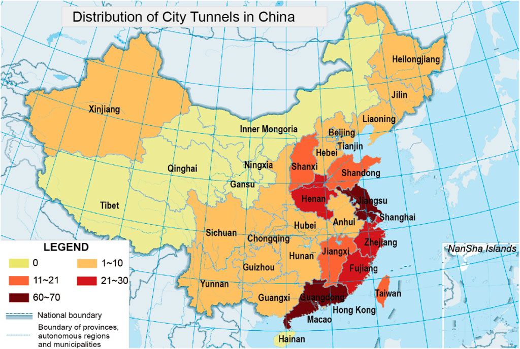
FIGURE 1. The distribution of city tunnels in China by 2021.
In contrast to single-hole tunnels, intersection tunnels possess unique characteristics, including complex structures, larger excavation sizes, and intricate spatial relationships (Lai et al., 2016; Chang et al., 2020; Yuan et al., 2022). Moreover, the complexities of city environments, such as intricate geological conditions, dense ground surface structures, and a network of criss-cross pipelines, expose intersection tunnel construction to significant safety risks (Huang et al., 2020a; Ma et al., 2021; Zhang et al., 2022). The process of constructing intersection tunnels inevitably involves repeated stress redistributions in the surrounding rock, exacerbating the instability of the rock and supporting structures. Consequently, this poses potential engineering disasters, such as the instability of existing tunnels and the collapse of ground buildings, thereby posing serious threats to urban safety. In response, scholars have undertaken research to ensure the safety and stability of intersection tunnel construction in cities, aiming to prevent engineering disasters and foster sustainable urban development.
To mitigate the engineering disaster risks associated with tunnel instability due to repeated disturbances in surrounding rock, scholars have diligently researched various aspects of tunnel excavation through theoretical analysis, numerical simulation, and on-site measurements (Ng et al., 2018; Yang et al., 2018; Xue et al., 2021). Some notable studies have focused on the mechanical behavior of surrounding rock, excavation methods, intersection angles, and spatial position relationships.
Wang et al. (Wang et al., 2020a; Wang et al., 2020b) delved into the mechanical behavior of surrounding rock during the excavation of branch tunnels. Their analysis led to the conclusion that the intersecting section represented the weakest part of the entire project, with its influence extending up to 40 m on the acute angle side and 20 m on the obtuse angle side from the intersection. Jin et al. (2018) conducted simulations on the construction process of deep buried intersection tunnels in areas with high ground stress, and discussed the mechanical behavior of surrounding rock and primary support structures under two distinct construction schemes. Additionally, Jin et al. (2009) compared and analyzed the mechanical characteristics of surrounding rock in intersecting and non-intersecting sections before and after transverse tunnel excavation, drawing insights from the Yangjiao tunnel project and establishing stress distribution patterns in cross-sections. Chen et al. (2015) performed dynamic monitoring measurements on both the excavating tunnel and existing tunnel during cross-section tunnel construction. Their findings provided valuable information on the mechanical behavior of surrounding rock and the stability of supporting structures in the tunnels. In another study, Liu et al. (2011) utilized the Juyunshan tunnel project as a case study for three-dimensional numerical simulations. They emphasized that ground stress and structural stress concentration were key factors influencing the stability of the crossing section.
By leveraging these research efforts, scholars aim to enhance the understanding of intersection tunnel construction, minimize risks of engineering disasters, and ensure the overall safety and stability of such complex projects.
To prevent the engineering disaster of ground buildings collapsing, researchers have thoroughly analyzed the deformation characteristics of structures through a combination of numerical simulation, on-site measurement, and monitoring techniques (Wang et al., 2018; Ayasrah et al., 2021; Ren et al., 2022; Wang et al., 2023). Fu (2021) utilized MIDAS/GTS software to assess the impact of shield tunneling on overlying buildings. Through this analysis, they obtained positive distribution curves of sedimentation tanks, providing valuable insights into potential settlement effects. Ding et al. (2019) developed a series of finite element models that considered the interaction between buildings, soil, and tunnels during the tunneling process. They analyzed the influence of structural stiffness and layout on the 3D deformation characteristics, providing a comprehensive understanding of how these factors affect structures. Lueprasert et al. (2017) focused on the evaluation of tunnel diameter and radial shrinkage as key indexes. They investigated the impacts of an adjacent loaded pile on an existing tunnel by varying the pile tip positions concerning the tunnel and soil stratum through three-dimensional elastic-plastic numerical analyses. Son (2015) conducted research using the discrete element method to study the influence of upper and adjacent buildings during tunnel construction, considering tunnel dimensions and construction conditions at various buried depths. They established relationships between these variables and the degree of building damage. Kuan et al. (Kuan et al., 2007; Kuan and Yang, 2008) established a numerical calculation model of shallow-buried tunnels using FLAC3D analysis software. They studied the effects of different factors on the characteristics of shallow-buried tunnels and surface settlement. Additionally, they explored the interactions between tunnels and surface structures under varying conditions.
These studies collectively contribute to the understanding of potential risks to ground buildings during tunnel construction, allowing for better-informed engineering decisions to mitigate the risk of collapse and enhance the safety of urban environments.
Numerous research studies have demonstrated that the center cross diagram (CRD) construction method offers several advantages, including uniform structure stress, minimal deformation, and high support stiffness (Jiang et al., 2018; Huang et al., 2020b; Huang et al., 2020c). These characteristics effectively reduce the degree of repeated disturbance to the surrounding rock during the construction of city intersection tunnels, thereby mitigating potential engineering disasters. Huo et al. (2019) focused on the selection of the construction method for urban tunnel and conducted numerical simulation and on-site monitoring on the construction of Shenyang Metro Line 9. They compared the settlement laws of the station baseplate under four construction methods (the full-face excavation method, the benching tunneling method, the side heading method and the center diaphragm method). It was concluded that the center diaphragm method is more suitable for urban tunnel engineering. Wang et al. (2020c) analyzed the stress characteristics of each excavation step and temporary supporting structure in the construction process of Re Shuitang No. 3 tunnel with CRD method, and put forward the key construction steps to control CRD method well. Strengthening the surrounding rock of the vault in advance is beneficial to ensure the construction safety. Zhang et al. (2023) analyzed the variation law of surface settlement during four excavation processes of CRD excavation method based on Yüan 1 railroad tunnel project, and believed that advance grouting could control the influence of CRD excavation method on surface settlement.
To assess the safety of tunnel structures and the stability of ground surface buildings during the construction process of city intersection tunnels using the CRD method, this paper presents a case study based on an underground circular roads project in the central business district (CBD) of Chongqing, China. The research investigates the variations of surrounding rock, the deformation of ground-affected buildings and the effects of the late excavation on the intersection tunnel through numerical simulation and on-site monitoring. By gaining insights from this study, it becomes possible to make informed decisions regarding the construction method selection for city intersection tunnels.
2 The CRD method
The CRD method adheres to the principle of “small blocks, short steps, multiple cycles, and quick closure,” making it particularly suitable for soft surrounding rock or long-span tunnels. The construction process involves step-by-step excavation on one side of the tunnel, followed by the implementation of the median lamella and diaphragm. Subsequently, the same procedure is applied to the other side of the tunnel, and the diaphragm is finalized (Jing et al., 2011; Wang et al., 2020c; Song et al., 2020). The detailed construction process of the CRD method can be divided into four steps, as illustrated in Figure 2. First step, the construction commences with the excavation of pilot-tunnel ➀, which is preceded by the reinforcement of the surrounding rock using advanced small pipes. Once the excavation is complete, the initial support is established. Second step, the pilot-tunnel ➁ is excavated and the corresponding initial support is put in place. Third step, the pilot-tunnel ➂ is excavated after reinforcing the surrounding rock, and the initial support is then completed. Fourth step, the construction advances to pilot-tunnel ➃, and the corresponding initial support is installed.
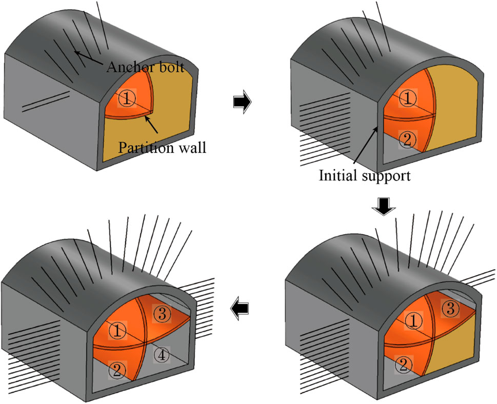
FIGURE 2. CRD method construction process. The ➀, ➁, ➂and ➃ represent the pilot-tunnel numbers.
The construction process of CRD method has the characteristics of short time for each pilot-tunnel to close and form a ring, uniform structure stress, small deformation and large support stiffness. Therefore, the tunnel overall deformation, the strata settlement and the influence on the ground building all are small during construction. Meanwhile, CRD method adopts small span construction making the disturbance range of each excavation step to the strata small, and the influence on the existing tunnel is reduced. Besides, temporary invert and median lamella wall not only increase the stiffness of tunnel structure, but also effectively restrain the deformation of the intersecting section. In summary, the CRD method’s construction process is well-designed to minimize disturbances to the surrounding environment, promote tunnel stability, and ensure the safety of adjacent structures during the building of city intersection tunnels.
3 Project overview
A significant underground circular roads project was undertaken in a CBD of Chongqing, China, aimed at resolving issues of traffic congestion and inadequate parking spaces. The project encompassed a total tunnel length of 2,580 m, comprising the main tunnel, as well as branch tunnels #1, #2, #3, #4, and #5. Notably, mileage segment K0+380 ∼ K0+420 of branch tunnel #1 and mileage segment K1+000 ∼ K1+160 of the main tunnel were buried at a depth of 40 m and intersected vertically at an angle close to 90°, as shown in Figure 3.
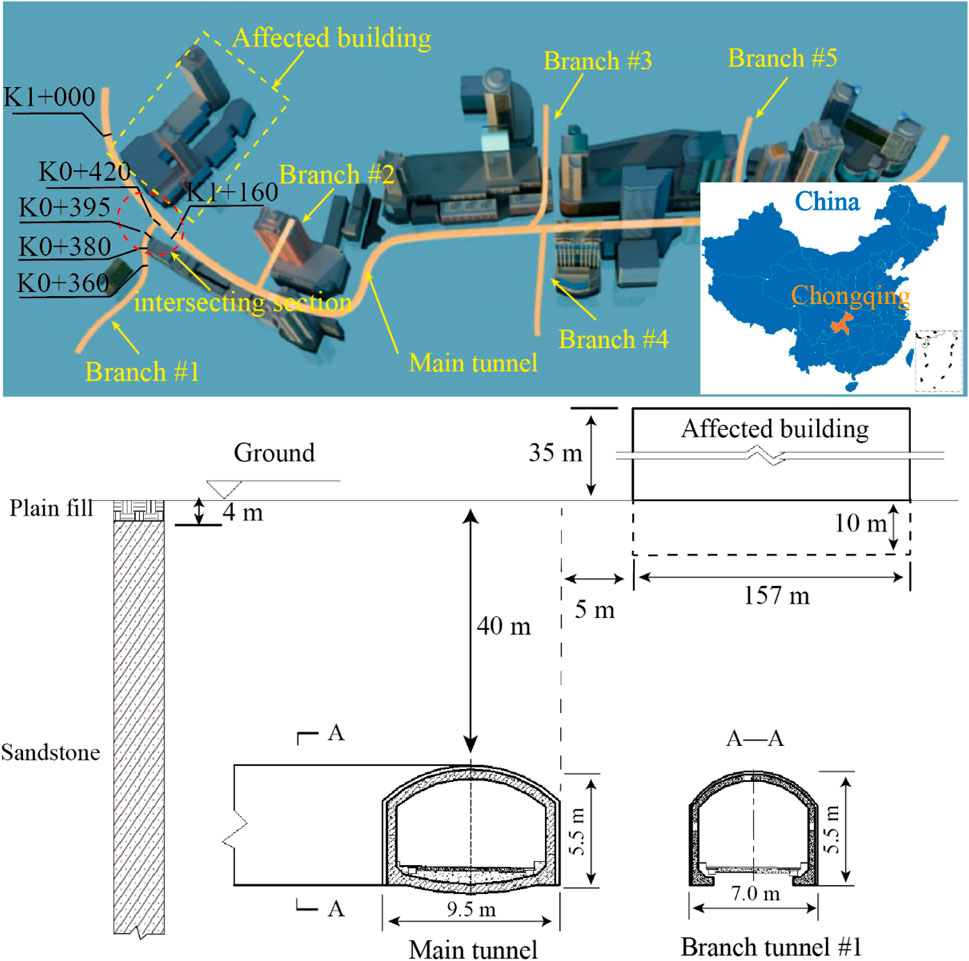
FIGURE 3. Intersection tunnel in the underground circular roads project.
The main tunnel was 9.5 m in width and 5.5 m in height, while the branch tunnel #1 was 7 m in width and 5.5 m in height. There was a ground building with 7 floors on the ground and 2 floors underground, and the minimum distance between it and the ground projection of intersecting section was 5 m. The hydrogeological conditions in the project area were relatively straightforward, with groundwater primarily comprising bedrock fissure water. The surrounding rock of the intersection tunnel primarily consisted of sandstone with two groups of fractures, categorized as soft rock of grade IV. Additionally, there was a 4 m-thick surface plain fill. The physical and mechanical parameters of each soil layer were shown in Table 1.
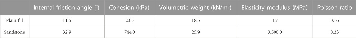
TABLE 1. Stratigraphic physical and mechanical parameters.
To avoid engineering disasters, the CRD method was employed for the construction of the intersecting section. The tunnel excavation sequence followed an order of upper left → lower left → upper right → lower right. The main tunnel would be excavated after the branch tunnel #1 was completed. The excavation interval of the pilot-tunnels is 7 m, for instance, the construction of the next pilot-tunnel begins when the previous pilot-tunnel is excavated 7 m. The excavated length of the pilot tunnel is 0.6 m each time. In the process of construction, some measures such as setting up anchor bolt, laying steel mesh, installing steel frame and spraying concrete are taken to strengthen the stability of surrounding rock.
4 Numerical simulation of city intersection tunnel
4.1 Numerical model creation
To conduct numerical simulations, a physical model representing the intersection tunnel was established using ANSYS simulation software, as shown in Figure 4. The model covered mileage segment K1+000 ∼ K1+160 of the main tunnel and mileage segment K0+380 ∼ K0+420 of branch tunnel #1. The dimensions of the model were 240 m in length, 160 m in width, and 70 m in height. The intersection tunnel had a depth of 40 m, and its cross-section shape was a semicircular arch. The main tunnel and branch tunnel #1 intersected vertically, forming a “T” shape. An affected building was located at a minimum distance of 5 m from the ground projection of the main tunnel on the ground surface. The building was simplified as a double-layer sheet structure. According to the geological survey report, the ground structure load of the affected ground building was 30 kN/m2 per floor, and the building had 7 floors on the ground. Therefore, its load-bearing capacity on the ground was represented by a uniformly distributed load of 210 kN/m2.
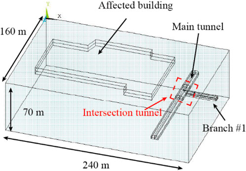
FIGURE 4. Numerical model of the city intersection tunnel.
In the model, the X-axis direction was perpendicular to the centerline of the main tunnel and pointed towards branch tunnel #1. The Y-axis direction was opposite to gravity, and the Z-axis direction was aligned with the centerline of the main tunnel. The upper boundary of the model was set to the ground surface.
The materials used in the model, such as rock, concrete, and soil, were considered granular materials with compressive strengths significantly higher than their tensile strengths. Additionally, when subjected to tensile forces, these materials exhibited expansion of their particles. To capture these characteristics, the Drucker-Prager yield criterion (Öztekin et al., 2016) was adopted as the constitutive relationship of materials in the numerical model. Given that the thickness of the plain fill was much smaller than the depth of the tunnels, it was disregarded in the model. The initial support structure was represented using a shell structure approach, and the materials for the surrounding rock and initial support were sandstone and C30 concrete, respectively, as shown in Table 2. The CRD method was adopted as the construction method, with an excavation sequence of upper left → lower left → upper right → lower right.
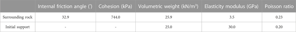
TABLE 2. Physical and mechanical parameters of surrounding rock and initial support material.
To ensure reality during the simulation, displacement constraints were applied. Specifically, a displacement constraint in the Z-direction was enforced on the boundary surface around the model, while a displacement constraint in the negative Y-direction was applied to the bottom surface of the model.
4.2 Results analysis
4.2.1 Influence of the main tunnel excavation on the ground building
After the completion of branch tunnel #1, the main tunnel construction commenced. After excavation of pilot-tunnel ➀, the maximum compressive stress and the maximum tensile stress of surrounding rock respectively were 2.80 MPa and 0.93 MPa. Besides, surrounding rock sank, resulting in the ground building to tilt 0.00123‰ to the right side. The maximum settlement value of the ground building was 0.193 mm, as shown in Figure 5. After the excavation of pilot-tunnel ➁, the maximum compressive stress and the maximum tensile stress of surrounding rock were both increased, which were 2.86 MPa and 0.97 MPa, respectively. The maximum settlement value of the ground building increased to 0.214 mm, and the slope to the right increased to 0.00136‰, as shown in Figure 6. After the excavation of pilot-tunnel ➂, the maximum compressive stress and the maximum tensile stress of surrounding rock increased to 3.81 MPa and 0.99 MPa. The maximum settlement value of the ground building increased to 0.552 mm, and the slope increased to 0.00351‰, as shown in Figure 7. After the excavation of pilot-tunnel ➃, the maximum compressive stress and the maximum tensile stress of surrounding rock suddenly decreased, which were 3.56 MPa and 0.76 MPa. The maximum settlement value of the ground building altered little, which was 0.556 mm. While the slope degree remained stable at 0.00354‰, as shown in Figure 8.
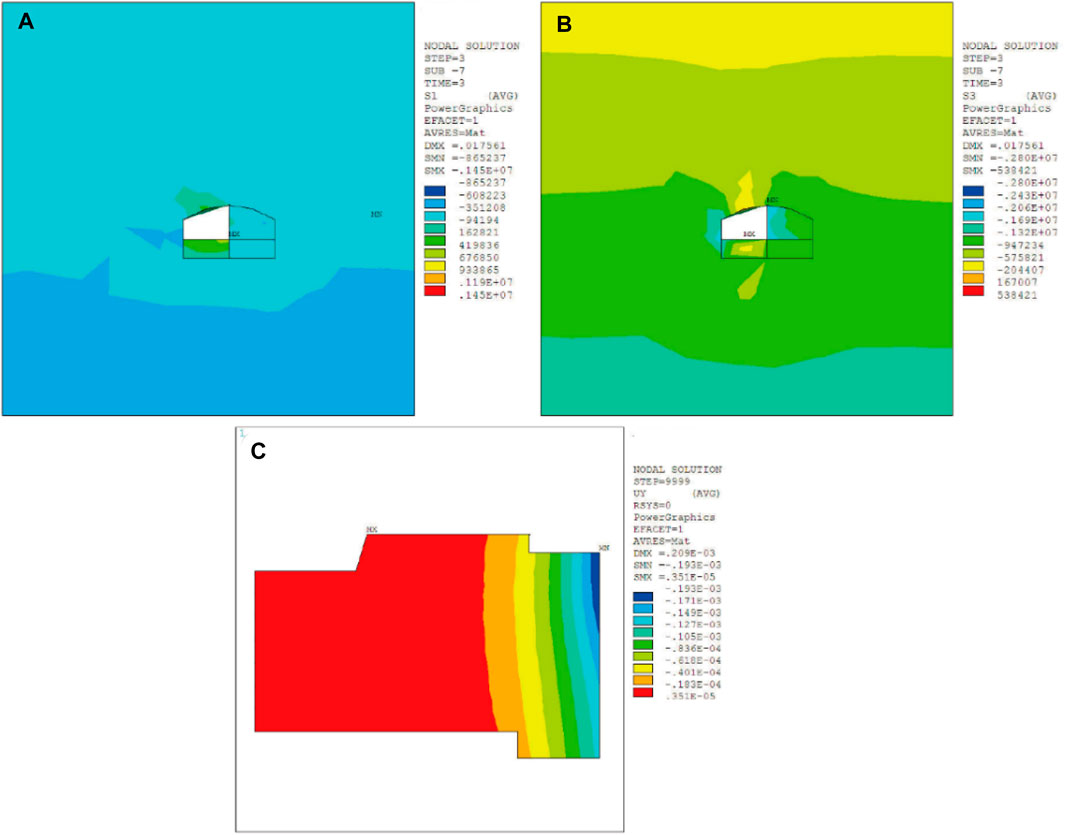
FIGURE 5. Influence of pilot-tunnel ➀ on surrounding rock and ground building. (A) The maximum principal stress of surrounding rock, (B) the minimum principal stress of surrounding rock, (C) displacement of ground building in Y-axis.
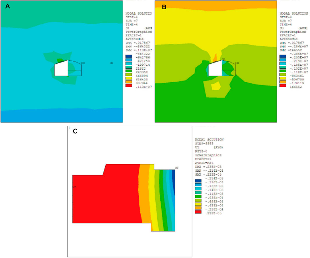
FIGURE 6. Influence of pilot-tunnel ➁ on surrounding rock and ground building. (A) The maximum principal stress of surrounding rock, (B) the minimum principal stress of surrounding rock, (C) displacement of ground building in Y-axis.
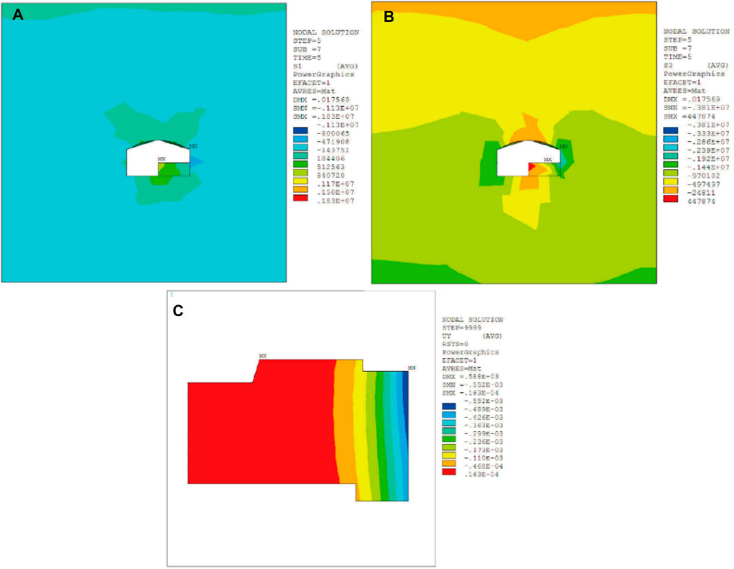
FIGURE 7. Influence of pilot-tunnel ➂ on surrounding rock and ground building. (A) The maximum principal stress of surrounding rock, (B) the minimum principal stress of surrounding rock, (C) displacement of ground building in Y-axis.
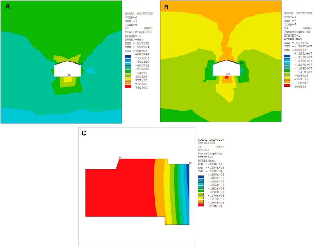
FIGURE 8. Influence of pilot-tunnel ➃ on surrounding rock and ground building. (A) The maximum principal stress of surrounding rock, (B) the minimum principal stress of surrounding rock, (C) displacement of ground building in Y-axis.
On the other hand, the deformation variation of the ground building showed a tendency of slow increase, sharp increase, and eventual stability during the excavation process of the main tunnel, as shown in Figure 9. This characteristic could be attributed to the structure form of the main tunnel in the construction process with CRD method. In the excavation process of the pilot-tunnel from ➀ to ➁, the main tunnel presented an incomplete semicircular arch and remained in a relatively stable structure, resulting in a slow settlement of the strata and ground building. However, in the excavation process of the pilot-tunnel from ➁ to ➂, the semicircular arch form was destroyed, and the tunnel structure became unstable, leading to a rapid settlement of the rock strata and ground building. After the completion of pilot-tunnel ➃, the main tunnel restored to a stable, complete semicircular arch structure, causing the strata and ground affected building to stabilize as well.
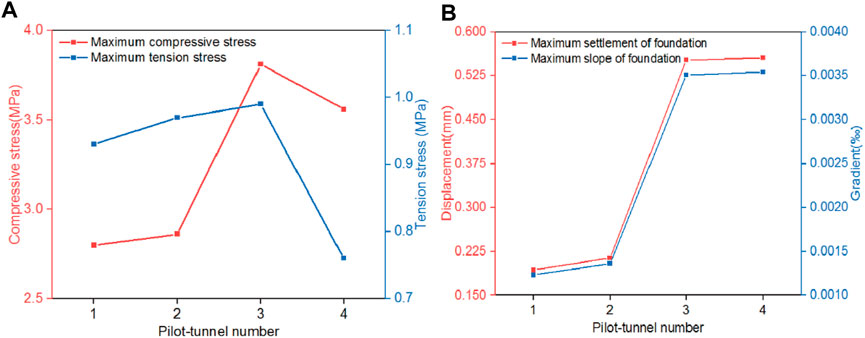
FIGURE 9. Influence of the main tunnel excavation process on surrounding rock and ground building under CRD method. (A) Compressive stress and tension stress of surrounding rock, (B) displacement and gradient of ground building.
4.2.2 Influence of the main tunnel excavation on the branch tunnel #1
The excavation of the main tunnel had significant effects on the stability of branch tunnel #1, leading to vault subsidence and arch haunch convergence, as shown in Figure 10. Before the excavation of the main tunnel, the vault subsidence of branch tunnel #1 gradually increased with the distance from the intersecting section and eventually stabilized at 1.449 mm at a distance of 14 m from the intersecting section.
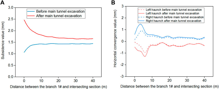
FIGURE 10. Deformation of the branch tunnel #1 before and after the main tunnel excavation. (A) Vault subsidence, (B) the horizontal convergence of the left and right arch haunches.
The vault subsidence value at the intersecting section was the smallest, which was 1.025 mm, as shown in Figure 10A. However, the excavation of the main tunnel altered the vault subsidence tendency of branch tunnel #1. After excavation, the vault subsidence gradually decreased with the distance from the intersecting section and stabilized at 14 m from the intersecting section. The vault subsidence value at the intersecting section was the maximum, which was 2.514 mm.
Regarding the horizontal convergence of the left and right arch haunches of branch tunnel #1, the main tunnel excavation did not change the convergence tendency, but it increased the maximum convergence values by 0.35 and 0.52 times, respectively. The horizontal convergence values of the left and right arch haunches increased first, then decreased, and eventually stabilized with an increase in distance from the intersecting section. The maximum values of horizontal convergence occurred at 6 m from the intersecting section, measuring 0.954 mm for the left arch haunch and 0.928 mm for the right arch haunch, as shown in Figure 10B.
These changes were primarily attributed to the alterations in the supporting structure of branch tunnel #1 at the intersection section. Before the excavation of the main tunnel, the intersecting section (K0+420) consisted of surrounding rock, which had a robust ability to limit deformation. However, after the main tunnel excavation, the intersecting section (K0+420) became a cavity with support materials, which had a relatively weaker ability to limit deformation.
The excavation of the main tunnel had significant effects on the rock strata stress situation of the branch tunnel #1, as shown in Figure 11. The rock strata near the vault of the branch tunnel #1 was mainly in compression state while the rock strata near the floor of the branch tunnel #1 was mainly in tension state. Although the excavation of the main tunnel did not affect the stress characteristics, it intensified the stress concentration. Before excavation of the main tunnel, the maximum compressive stress and tensile stress of rock strata were 2.50 MPa and 0.73 MPa, respectively. The maximum compressive stress and tensile stress of rock strata increased to 3.56 MPa and 0.76 MPa under the influence of the main tunnel excavation.
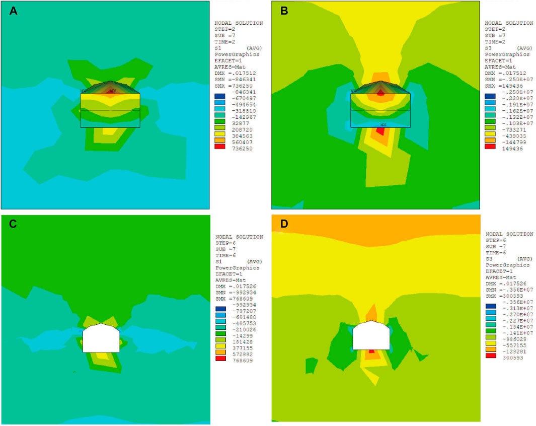
FIGURE 11. The rock strata stress of the branch tunnel #1 before and after the main tunnel excavation. (A) The maximum principal stress before the main tunnel excavation, (B) the minimum principal stress before the main tunnel excavation, (C) the maximum principal stress after the main tunnel excavation, (D) the minimum principal stress after the main tunnel excavation.
5 Field monitoring
The occurrence of existing tunnel instability is a unique engineering disaster in intersection tunnel projects. To analyze the influence of main tunnel construction under the CRD method on the stability of branch tunnel #1, the horizontal convergence and vault subsidence of the branch tunnel #1 were monitored through electronic total station, as shown in Figure 12. A continuous monitoring was conducted on cross-sections K0+395 and K0+360 when the main tunnel excavation reached the intersecting section (K1+120 section). Cross-sections K0+395 and K0+360 were located 25 m and 60 m away from the intersecting end face, respectively.
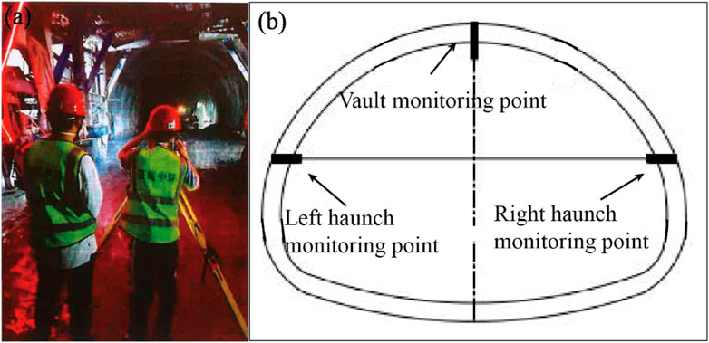
FIGURE 12. Monitoring measurement of the branch tunnel 1#. (A) Situation on site, (B) monitoring points.
The cumulative deformation characteristics of both cross-sections exhibited similar patterns, which could be categorized into three stages: rapid deformation stage, deceleration deformation stage and stable deformation stage, as shown in Figure 13.
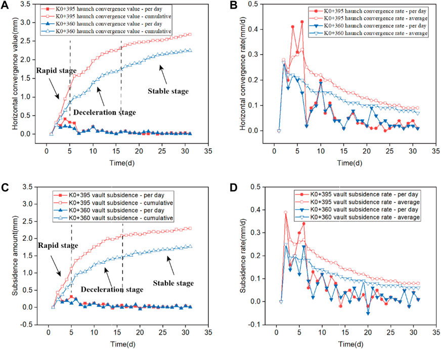
FIGURE 13. Monitoring deformation of K0+395 and K0+360 cross-sections. (A) Arch haunch horizontal convergence value, (B) arch haunch horizontal convergence rate, (C) vault subsidence value, (D) vault subsidence rate.
Rapid deformation stage: During the initial monitoring period of 0–5 days, the cumulative deformation curves (horizontal convergence and vault subsidence) of the two cross-sections showed a steep upward trend with a large daily deformation rate. The deformation during this stage accounted for approximately 57% of the total deformation. Deceleration deformation stage: From day 6 to day 16 of monitoring, the cumulative deformation curves of the two cross-sections displayed a gradual upward trend with a reduced daily deformation rate. The deformation during this stage accounted for about 32% of the total deformation. Stable deformation stage: After 17 days of monitoring, the cumulative deformation curves of the two cross-sections reached a stable state, with a daily deformation rate remaining at a small value (daily horizontal convergence rate of 0.04 mm/d and daily subsidence rate of 0.05 mm/d). The deformation during this stage accounted for approximately 11% of the total deformation. The maximum arch subsidence value of branch tunnel #1 monitored through electronic total station was 2.39 mm while the value calculated by numerical simulation was 2.51 mm. The difference of results is 4.7%, which is within the margin of error. It could be proved that the numerical simulation results were reliable.
The deformation characteristic of the three stages was inferred to be related to the dynamic distance between the construction face and the monitoring cross-sections. During the rapid deformation stage, the construction face was in close proximity to the monitoring cross-section, resulting in significant rock mass breakage and crumpling due to construction disturbance. As a result, the deformation at the monitoring sections was substantial. As the construction face moved away from the monitoring cross-section during the deceleration deformation stage, the construction disturbance effect on the monitoring cross-section gradually decreased. In the stable deformation stage, the construction face was far away from the monitoring cross-section, and the construction disturbance had no significant impact on the monitoring cross-section.
Additionally, it was observed that both the deformation convergence value and convergence rate of cross-section K0+360 were consistently smaller than those of cross-section K0+395 at each stage of monitoring. The final horizontal convergence value and subsidence value of cross-section K0+360 were measured at 2.25 mm and 1.92 mm, respectively. These values were approximately 84% and 78% of those observed at cross-section K0+395, which had a final horizontal convergence value of 2.68 mm and a final subsidence value of 2.45 mm, as shown in Figures 13A, C. The characteristic accorded with the regulation obtained in Section 4.2.3 that the horizontal convergence value and vault subsidence value decreased with an increase in distance from the intersecting section. This characteristic was inferred to be related to the absolute distance between the construction face and the monitoring cross-section. Cross-section K0+360, being further away from the construction face, experienced less disturbance and was thus less affected by the construction activities. In contrast, cross-section K0+395, being closer to the construction face, experienced a higher degree of disturbance, resulting in more significant deformation.
6 Conclusion
This paper analyzed the influences of CRD construction processes on the stress and displacement of surrounding rock based on an underground circular roads project in Chongqing, China. It was revealed that the excavation of pilot-tunnel ➃ would reduce the surrounding rock stress and control the rock strata subsidence. The excavation of pilot-tunnel ➃ was the key step of CRD method.
(1) The stress variation in the surrounding rock during the CRD method excavation exhibited a trend of increasing and then decreasing due to the structural form of the tunnel after excavation. The maximum compressive stress and maximum tensile stress increased gradually with the excavation of the pilot-tunnels ➀ to ➂, but decreased after the excavation of the pilot-tunnel ➃.
(2) The deformation of the ground building during the CRD method excavation showed a progression from slow increase to sharp increase and finally to stability. The ground building experienced slow sinking and tilting to the right during the excavation of the pilot-tunnels ➀ to ➁, followed by rapid sinking and sharp tilting during the excavation of the pilot-tunnels ➁ to ➂, and eventually stabilized after the excavation of the pilot-tunnel ➃.
(3) The excavation of the main tunnel had significant effects on the vault subsidence and arch haunch convergence of branch tunnel #1. The main tunnel excavation resulted in an increase of 0.73 times in the maximum vault subsidence value, 0.35 times in the maximum left arch haunch convergence value, and 0.52 times in the maximum right arch haunch convergence value of branch tunnel #1.
(4) The cumulative deformation the cross-sections K0+395 and K0+360 was divided into three stages of rapid deformation, deceleration deformation, and stable deformation, which was attributed to the dynamic distance between the construction face and the monitoring cross-section. Additionally, the final horizontal convergence value and subsidence value of cross-section K0+360 were approximately 84% and 78% of those observed at cross-section K0+395, respectively, due to the absolute distance between the construction face and the monitoring cross-section.
Data availability statement
The original contributions presented in the study are included in the article/supplementary material, further inquiries can be directed to the corresponding author.
Author contributions
YR: Data curation, Formal Analysis, Methodology, Resources, Software, Validation, Visualization, Writing–original draft, Writing–review and editing. SZ: Conceptualization, Formal Analysis, Investigation, Project administration, Software, Supervision, Visualization, Writing–original draft, Writing–review and editing. JJ: Conceptualization, Methodology, Resources, Supervision, Validation, Visualization, Writing–review and editing. QY: Funding acquisition, Investigation, Methodology, Project administration, Resources, Validation, Writing–original draft, Writing–review and editing. ZZ: Conceptualization, Data curation, Project administration, Software, Validation, Visualization, Writing–review and editing. ML: Data curation, Formal Analysis, Investigation, Resources, Supervision, Writing–original draft. HH: Data curation, Resources, Software, Validation, Writing–original draft.
Funding
The author(s) declare financial support was received for the research, authorship, and/or publication of this article. This research was funded by the Open Science Foundation Project Funded by State Key Laboratory of Coal Mine Disaster Dynamics and Control, grant number 2011DA105287-MS202210, and the National Nature Science Foundation of China, grant number 52004243.
Conflict of interest
Authors SZ and JJ were employed by the company Chongqing Zhonghuan Construction Co., Ltd. Author ZZ was employed by the company China 19th Metallurgical Corporation. Author ML was employed by the company Chongqing City Construction Investment (Group) Co., Ltd. Author HH was employed by the company Shanghai Jianke Engineering Consulting Co., Ltd.
The remaining authors declare that the research was conducted in the absence of any commercial or financial relationships that could be construed as a potential conflict of interest.
Publisher’s note
All claims expressed in this article are solely those of the authors and do not necessarily represent those of their affiliated organizations, or those of the publisher, the editors and the reviewers. Any product that may be evaluated in this article, or claim that may be made by its manufacturer, is not guaranteed or endorsed by the publisher.
References
Ayasrah, M. M., Qiu, H., and Zhang, X. (2021). Influence of Cairo metro tunnel excavation on pile deep foundation of the adjacent underground structures: numerical study. Symmetry 13, 426. doi:10.3390/sym13030426
Chang, Z., Du, Z., Zhang, F., Huang, F., Chen, J., Li, W., et al. (2020). Landslide susceptibility prediction based on remote sensing images and GIS: comparisons of supervised and unsupervised machine learning models. Remote Sens. 12 (3), 502. doi:10.3390/rs12030502
Chen, W., Zheng, D., Yu, J., Yuan, J., Liu, H., and Tian, H. (2015). Study on stability of close cross tunnel on existing tunnel. Chin. J. Rock Mech. Eng. 34 (S1), 3097–3105. doi:10.13722/j.cnki.jrme.2013.1809
Ding, Z., Ji, X., Li, X., and Wen, J. (2019). Numerical investigation of 3D deformations of existing buildings induced by tunnelling. Geotechnical Geol. Eng. 37 (4), 2611–2623. doi:10.1007/s10706-018-00781-1
Fu, Y. (2021). Analysis on the impact of shield tunneling on overlying buildings. Railw. Constr. Technol. (02), 146–150. doi:10.3969/j.issn.1009-4539.2021.02.033
Huang, F., Cao, Z., Guo, J., Jiang, S.-H., Li, S., and Guo, Z. (2020a). Comparisons of heuristic, general statistical and machine learning models for landslide susceptibility prediction and mapping. CATENA 191, 104580. doi:10.1016/j.catena.2020.104580
Huang, F., Cao, Z., Jiang, S.-H., Zhou, C., Huang, J., and Guo, Z. (2020b). Landslide susceptibility prediction based on a semi-supervised multiple-layer perceptron model. Landslides 17 (12), 2919–2930. doi:10.1007/s10346-020-01473-9
Huang, F., Zhang, J., Zhou, C., Wang, Y., Huang, J., and Zhu, L. (2020c). A deep learning algorithm using a fully connected sparse autoencoder neural network for landslide susceptibility prediction. Landslides 17 (1), 217–229. doi:10.1007/s10346-019-01274-9
Huo, R., Zhou, P., Song, Z., Wang, J., Li, S., and Zhang, Y. (2019). Study on the settlement of large-span metro station’s baseplate caused by the tunnels newly built beneath it. Adv. Mech. Eng. 11 (2), 168781401882516–13. doi:10.1177/1687814018825161
Jiang, S., Huang, J., Huang, F., Yang, J., Yao, C., and Zhou, C.-B. (2018). Modelling of spatial variability of soil undrained shear strength by conditional random fields for slope reliability analysis. Appl. Math. Model. 63, 374–389. doi:10.1016/j.apm.2018.06.030
Jin, X., Zhang, X., Li, Y., and Lin, Z. (2009). 3D finite element research on dynamic construction mechanics for a large-sized underground interchange. Chin. J. Undergr. Space Eng. 5 (02), 215–219. doi:10.3969/j.issn.1673-0836.2009.02.003
Jin, X., Yang, Q., and Qiu, F. (2018). Mechanical effect of construction of duct over the subway tunnel with small-distance. J. Chongqing Jiaot. Univ. Sci. 37 (05), 23–28+70. doi:10.3969/j.issn.1674-0696.2018.05.05
Jing, A.-N., Li, P., and Shi, H. (2011). Shallow depth of the tunnel excavation response research based on CRD method. Procedia Eng. 15, 4852–4856. doi:10.1016/j.proeng.2011.08.905
Kuan, X., and Yang, H. (2008). Effects of horizontal distance between superstructure and tunnel on behaviors of shallow tunnel and settlements of superstructure. Highw. Eng. (02), 10–15. doi:10.3969/j.issn.1674-0610.2008.02.003
Kuan, X., Yang, H., Mao, Q., and Pan, X. (2007). Effects of reinforcement on behaviour of shallow tunnel and settlement of ground surface. Highw. Eng. (04), 82–86. doi:10.3969/j.issn.1674-0610.2007.04.021
Lai, J., Wang, K., Qiu, J., Niu, F., Wang, J., and Chen, J. (2016). Vibration response characteristics of the cross tunnel structure. Shock Vib. 2016, 1–16. doi:10.1155/2016/9524206
Liu, S., Chen, Y., and Li, G. (2011). Numerical analysis of local stability at intersection parts of tunnel. J. Chongqing Jiaot. Univ. Nat. Sci. 30 (02), 217–220.
Lueprasert, P., Jongpradist, P., Jongpradist, P., and Suwansawat, S. (2017). Numerical investigation of tunnel deformation due to adjacent loaded pile and pile-soil-tunnel interaction. Tunn. Undergr. Space Technol. 70, 166–181. doi:10.1016/j.tust.2017.08.006
Ma, L. H., Jiang, X., Chen, J., Zhao, Y. F., Liu, R., and Ren, S. (2021). Analysis of damages in layered surrounding rocks induced by blasting during tunnel construction. Int. J. Struct. Stab. Dyn. 21 (07), 2150089. doi:10.1142/s0219455421500899
Ng, C. W. W., Fong, K. Y., and Liu, H. L. (2018). The effects of existing horseshoe-shaped tunnel sizes on circular crossing tunnel interactions: three-dimensional numerical analyses. Tunn. Undergr. Space Technol. 77, 68–79. doi:10.1016/j.tust.2018.03.025
Öztekin, E., Pul, S., and Hüsem, M. (2016). Experimental determination of Drucker-Prager yield criterion parameters for normal and high strength concretes under triaxial compression. Constr. Build. Mater. 112, 725–732. doi:10.1016/j.conbuildmat.2016.02.127
Ren, T., Zhang, H., Guo, Y., Tang, Y., and Li, Q. (2022). Numerical simulation of ground surface settlement of underpass building in tunnel boring machine double-line tunnels. Front. Earth Sci. 10, 937524. doi:10.3389/feart.2022.937524
Son, M. (2015). Response analysis of nearby structures to tunneling-induced ground movements in sandy soils. Tunn. Undergr. Space Technol. 48, 156–169. doi:10.1016/j.tust.2015.03.008
Song, Z., Tian, X., Liu, Q., Zhang, Y., Li, H., and Zhou, G. (2020). Numerical analysis and application of the construction method for the small interval tunnel in the turn line of metro. Sci. Prog. 103 (3), 003685042093206. doi:10.1177/0036850420932067
Wang, Y. Q., Kong, W. K., and Wang, Z. F. (2018). Effect of expanding a rectangular tunnel on adjacent structures. Adv. Civ. Eng. 10, 1–13. doi:10.1155/2018/1729041
Wang, J., Wang, L., Ma, J., and He, X. (2020a). Karst investigation and the countermeasures in Xinjie tunnel of the Kaili Ring highway, Guizhou province. Geotech. Eng. Tech. 34 (05), 276–281+285. doi:10.3969/j.issn.1007-2993.2020.05.007
Wang, J., Wang, L., Ma, J., Song, S., and Huang, P. (2020b). Protective effect of microRNA‑340‑5p against oxygen‑glucose deprivation/reperfusion in PC12 cells through targeting neuronal differentiation 4. Chin. J. Undergr. Space Eng. 16 (S2), 964–974. doi:10.3892/mmr.2020.11174
Wang, Z., Yang, R., Guo, H., and Li, K. (2020c). Study on key construction procedures of CRD method for Re Shuitang No.3 tunnel. IOP Conf. Ser. Mater. Sci. Eng. 711 (1), 012074. doi:10.1088/1757-899x/711/1/012074
Wang, S., Song, Z., Tian, X., Sun, Y., and Zhang, Y. (2023). Prediction for the surface settlement of double-track subway tunnels for shallow buried loess based on peck formula. Front. Earth Sci. 11, 1219544. doi:10.3389/feart.2023.1219544
Xu, F., Du, Z., and Chen, C. (2022). Distribution and development characteristics of urban road tunnels in China. Mod. Tunn. Technol. 59 (06), 35–41+69. doi:10.13807/j.cnki.mtt.2022.06.004
Xue, F., Cai, M., Wang, T., and Zhao, T. (2021). Characteristics of Karst cave development in urban Karst area and its effect on the stability of subway tunnel construction. Adv. Civ. Eng. 2021, 1–12. doi:10.1155/2021/8894713
Yang, F., Cao, S., and Qin, G. (2018). Performance of the prestressed composite lining of a tunnel: case study of the Yellow River crossing tunnel. Int. J. Civ. Eng. 16, 229–241. doi:10.1007/s40999-016-0124-0
Yuan, F., Liu, Y., Xu, Q., Zheng, Y., Hu, L., Zhao, P., et al. (2022). Study on mechanical characteristics and construction control of the railway overlapping Tunnels. Front. Earth Sci. 10, 857172. doi:10.3389/feart.2022.857172
Zhang, Z., Zhao, C., Peng, L., Zhang, X., and Lei, M. (2022). Research on the stability of shallow-buried large cross-section tunnel by construction method conversion. Front. Earth Sci. 10, 831169. doi:10.3389/feart.2022.831169
Keywords: city intersection tunnel, CRD method, engineering disasters, numerical simulation, in-situ monitoring
Citation: Ren Y, Zhou S, Jia J, Yuan Q, Zhou Z, Liu M and He H (2023) Construction stability analysis of intersection tunnel in city under CRD method. Front. Earth Sci. 11:1264140. doi: 10.3389/feart.2023.1264140
Received: 20 July 2023; Accepted: 29 September 2023;
Published: 26 October 2023.
Edited by:
Faming Huang, Nanchang University, ChinaReviewed by:
Geyang Song, Other, United KingdomQi Liu, Shandong University of Science and Technology, China
Copyright © 2023 Ren, Zhou, Jia, Yuan, Zhou, Liu and He. This is an open-access article distributed under the terms of the Creative Commons Attribution License (CC BY). The use, distribution or reproduction in other forums is permitted, provided the original author(s) and the copyright owner(s) are credited and that the original publication in this journal is cited, in accordance with accepted academic practice. No use, distribution or reproduction is permitted which does not comply with these terms.
*Correspondence: Qiang Yuan, cWlhbmd5dWFuQGNxdS5lZHUuY24=