 Rui Yang
 Qian Kong1,2
- 1CCCC Second Harbour Engineering Co., Ltd., Wuhan, China
- 2CCCC Highway Bridge National Engineering Research Centre Co., Ltd., Beijing, China
- 3Hohai University Institute of GeoEnvironmental, Nanjing, China
Tunnel excavation is prone to segment cracks, which may lead to serious safety accidents. This work aims to investigate the type, location and occurrence time of cracks in a large-diameter underwater shield tunnel and also ascertain the causes of the cracks. The correlations between crack characteristics and shield tunneling parameters were analyzed. The effect of jack deflection and poor assembly on cracks were investigated using a refined finite element model of two consecutive rings with consideration of the assembly clearance and the constraint effect of the shield machine. The results confirmed that 93% of the cracks were formed between the current ring and the last ring jacking stage. Positive cracks induced by jack deflection occurred during the current ring jacking stage, while the lengths of the cracks, proportional to the constraint of the boring machine on the segments, remained constant during the subsequent construction process. The cracks caused by poor assembly quality arose during the current and next ring jacking stages. Furthermore, the cracks generated in the current ring jacking stage would propagate during the subsequent construction process. The type, length, and number of cracks were influenced by the assembly clearance. The inverted V-shape longitudinal joints caused more cracks than any other assembly defects. The finding of this study results and conclusions are expected to contribute to the reduction of cracks at the jacking stage of the large-diameter underwater shield tunnels with eccentricity force transfer platforms.
1 Introduction
Large-diameter shield tunnels have already become the most popular solution to relieve the pressure of the crosse river transportation. For such tunnels, segment lining cracks are one of the primary structural safety issues. These cracks may occur at various stages such as segment transportation, segment hoisting, tunnel construction and operation, while most of them are produced during the shield tunneling process (Chen and Mo, 2009; Shayanfar et al., 2017). Segment cracks not only affect the appearance of tunnels but also lead to hazards and reduce the functionality and durability of tunnels. Developed cracks can even threaten the safety of the tunnels (Sugimoto, 2006; Xu et al., 2019). Therefore, it is essential to study the causes of cracks, so as to prevent the occurrence of cracks in the segment linings.
The most common segment cracks can be classified as longitudinal, corner, U-shaped and circumferential cracks (Gruebl, 2006; Sugimoto, 2006; Chen and Mo, 2009; Shayanfar et al., 2017; Xu et al., 2019). The causes of longitudinal cracks include jack eccentricity, jack deflection, uneven support, uneven thrust, inconsistent jacking speeds, assembly angles, and uneven regional pressures of the upper and lower jacks (Burgers et al., 2007; Cavalaro et al., 2011; Lu et al., 2017; Lu et al., 2018.; Sharghi et al., 2021). When the jack boot is eccentric or the jack is at a deflection angle to the segment, a bending moment toward the outer arc of the segment would be generated, which may loosen the longitudinal joints and lead to joint openings. The joint openings lead to uneven support, causing tension on the front end of the segment (Burgers et al., 2007; Sharghi et al., 2021), which results in positive longitudinal cracks between the two jack boots (Lu et al., 2018). In addition, inconsistent jacking speed, uneven regional pressures in the upper and lower jacks, and the presence of there is a longitudinal moments at the front end of the segment, can lead to temporary or permanent positive cracks (Koyama, 2003; Xu and Zhang, 2013; Lu et al., 2017; Lorenzo, 2021). During the construction of shield tunnels, the segment at the unsolidified position of the grouting behind the wall can be considered as a simply supported beam that is restrained by the shield machine in the front and by the completed tunnel in the rear. When the difference in regional pressure between the upper and lower or left and right jacks is too large, a bending moment on the transverse axis of the tunnel would be generated at the rear of the shield machine (Liu et al., 2023a). As a result, the segments in the weakly constrained region are under tensile stress, and form the circumferential cracks (Mo and Chen, 2008). Corner cracks are generally attributed to the loose bolts or wide longitudinal (radial) joints, which could lead to collisions or uneven contacts between segments during the assembly process (Burgers et al., 2007; Cavalaro, 2009). U-shaped cracks are usually located between the end face and the handhole. These U-shaped cracks occur when adjacent segments are not aligned with each other due to the rotation, which may lead to compression between segments and the compression of the bolt rod against the bolt hole (Chen and Mo, 2009). Besides small shield tail clearance, improper shield posture, poor assembly quality and change in the longitudinal slope of the tunnel can also lead to cracks in the segment linings, despite the fact that it is still not clear which kind of cracks are subjected to these causes (Mo and Chen, 2008; Cavalaro, 2009; Yang et al., 2018; Ahmadi and Molladavoodi, 2019; Liu et al., 2020; Dai et al., 2022). Macroscopic or microscopic experimental tests, deep learning-based method, and numerical simulations are effective approaches to investigate the cracks (Liu et al., 2023b; Gao et al., 2023; Liu and Li, 2023). However, the mechanical conditions of the segments inside the shield machine are very complicated, which poses challenges to fully consider various factors during experimental testing. Therefore, many experimental studies have focused on the single factor, such as jack eccentricity and limit thrust (Hemmy, 2001; Plizzari and Tiberti, 2007; Li et al., 2015; Nogales and Fuente, 2020). Due to the simplicity of the numerical simulations, more factors like the effect of rotation between segments, uneven support, uneven thrust, jack eccentricity, and jack deflection, have been selected for investigation in the scientific literatures (Mohtadinia et al., 2020; Krahl et al., 2021; Tian et al., 2021).
It should be noted that most of previous studies on segment cracks were performed on the premise that the tunnel was completed, whereas the crack data obtained during the shield tunneling were limited. Hence, there is missing information on the detailed occurrence time of the cracks was lacking. Numerical simulations on segment generally concentrated on a specific ring assembling or jacking stage. These studies assumed the cracks of the segment rings only occurred during the construction of the selected ring and failed to consider the effect of subsequent construction as well as the cracking behaviors of adjacent rings on the crack generation. In addition, the influence of the joint clearance and the restraint of the shield tail on the segments were also not taken into account.
In present study, 927 cracks in 1225 ring segments of a large-diameter shield tunnel with the eccentric force transfer platforms in Bangladesh were examined in terms of the type, quantity, location and occurrence time. Based on the selected tunneling parameters and a refined model of two consecutive segment rings considering the assembly clearance, the type, distribution, expansion, and occurrence time of segment cracks in the scenarios of shield attitude adjustment and poor assembly during the process of jacking two consecutive rings were investigated. The findings are expected to provide some guidelines for reduction of cracks at the jacking stage of large-diameter underwater shield tunnels with segment eccentric force transfer platforms.
2 Background
2.1 Project overview
The Karnapuri River tunnel is located in Chittagong, Bangladesh and connects the east and west banks of Karnapuri River at the estuary. The shield tunnel is 2450 m long and is assembled with 1225 ring segments. The tunnel depth ranges from approximately 7–32 m, with a maximum water pressure of about 4 bar. The stratigraphic distribution of the tunnel site is shown in Figure 1.
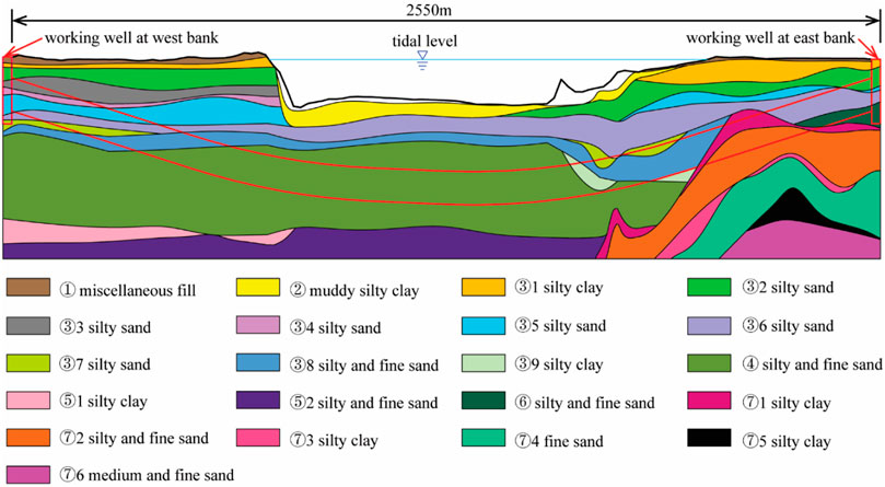
FIGURE 1. Geological profile of the tunnel.
2.2 Design of segment and shield tail
The outer diameter of the tunnel is 10.8 m, and the thickness of the segment is 0.5 m, and the width of the segment is 2 m. Each ring lining consists of 1 K segment, two adjacent segments (L1, L2), and five standard segments (B1–B5). The longitudinal joints are connected by Class 8.8 M30 bolts, while the circumferential joints are connected by Class 8.8 M36 bolts. The central angle of the adjacent segments and the standard segments is 46.9°, and the central angle of the K segment is 31.7°. Each adjacent and standard segment has three force transfer platforms, and the K segment has two force transfer platforms. The thickness of the force transfer platform is 4 mm.
The dimensions of the segments, as well as the dimensions and positions of the force transfer platform, hand holes, and bolt holes as shown in Figure 2. It is worth noting that there was a 32-mm deviation between the center lines of the force transfer platforms and the center line of the segment (Figure 2B). As the positions of the force transfer platforms are the same as those of the jacks, the forces acting on the segment is always eccentric during the jacking process.
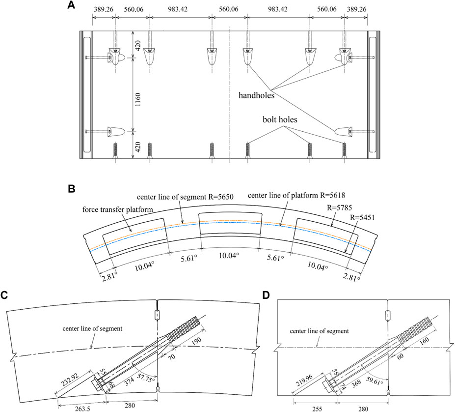
FIGURE 2. (A) Unfolded drawing of the inner curved surface of the segment (B) Drawing of the force transfer lug position and dimension (C) Drawing of the longitudinal seam joint (D) Drawing of the circumferential seam joint (unit: mm).
The shield machine is equipped with 23 jacks, which are divided into four zones. Jacks No. 21–23 and No. 1–3, No. 4–8, No. 9–15, and No. 16–20 are in the upper, right, lower and left zones, respectively. The central angles of the upper, lower, left, and right zones are 94°, 110°, 78°, and 78°, respectively (Figure 3A).
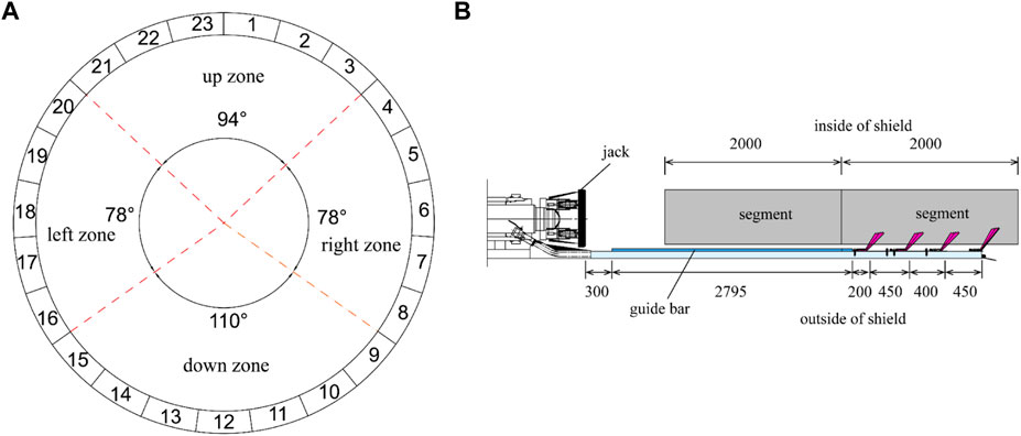
FIGURE 3. (A) Serial number and partition of jack (B) side view of shield tail (unit: mm).
Guide bars are installed at the tail of the shield machine to avoid excessive jack deflection angles. The dimensions of the guide bars are 30 mm in height, 50 mm in width, 2795 mm in length and they are arranged in a circumferential direction, with a central angle of 8° between adjacent guide bars. The distance between the guide bar and the jack is 300 mm. There are four shield tail brushes at machine tail. The distances from the end of the guide bars for the four tail brushes are 200, 650, 1050, and 1500 mm, respectively (Figure 3B).
3 Statistical analysis of segment cracks
3.1 Segmental cracks in shield tunnel
A total of 927 cracks were identified in the left tunnel, and the segment rings with cracks accounted for 47.7% of the total number of segment rings. The cracks could be divided into five types: positive, backward, handhole, corner and circumferential cracks. The handhole cracks started from the end of the bolts and developed obliquely (Figure 4).
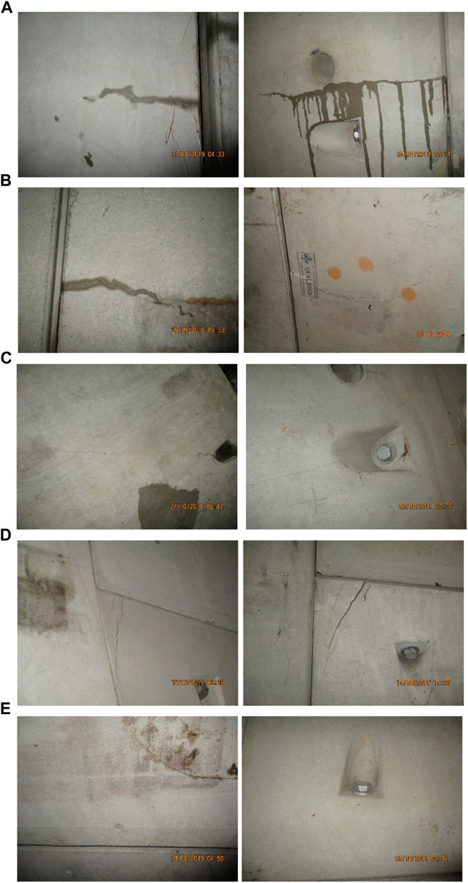
FIGURE 4. Typical cracks: (A) positive crack, (B) backward crack, (C) bolt crack, (D) corner crack, and (E) circumferential crack.
The proportion of each crack type is illustrated in Figure 5. Positive cracks accounted for the largest proportion, followed by the backward and circumferential cracks. These three types of cracks accounted for 95% of the total cracks. The focus of the work was therefore on the causes of the longitudinal and circumferential cracks.
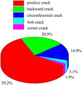
FIGURE 5. Proportions of different types of cracks.
Considering that the dominant loads acting on segments were the thrust of the jacks before the segments were pushed out from the shield tail, the number of longitudinal cracks at locations of the 23 jacks was counted (Figure 6). The longitudinal cracks occurred mainly in the down zone of the jacks, followed by the left zone. Cracks in the lower and left zones accounted for 76% and 16.21% of the total cracks, respectively. Of the 23 jacks, the largest proportion of longitudinal cracks was found at jacks 13 and 14, which were mainly in the down zone closest to the left zone of the jack.
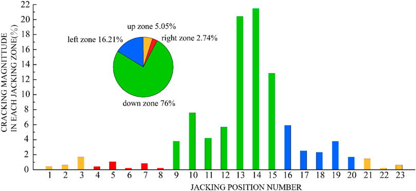
FIGURE 6. Cracking magnitudes in different jacking zones.
To investigate the relationship between the cracks and segment type, eight segments were divided into 23 zones (labelled as A–W), with the boundary of the adjacent zones being the bisector between the two force transfer platforms (Figure 7A).
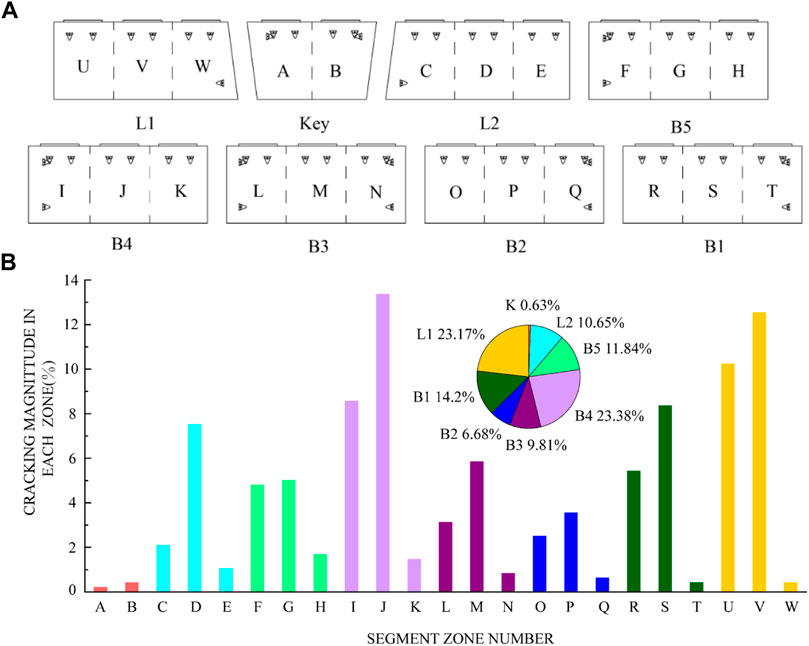
FIGURE 7. (A) Zoning of the segmental linings for statistical examination (B) Cracking magnitude in different segment zones.
Figure 7B lists the numbers of longitudinal cracks in each zone of the different segments. The largest proportion of longitudinal cracks was in zone J, followed by zone V. The segment with the most longitudinal cracks was B5, followed by L1, and the K segment had the least longitudinal cracks. For each segment, the zone with the largest proportion of cracks was the force transfer platform in the middle part, followed by the force transfer platform on the left.
The segments were assembled with staggered joints. Therefore, the segments could be divided into two types, namely, i.e., Type A and Type B according to the positional of the longitudinal joints of the front and rear rings in relation to and the segment of the objective ring, with the exception of the K segment. The proportion of longitudinal cracks in each type of segment is shown in Figure 8. Overall, 73.5% of the longitudinal cracks were observed in Type-A segments.
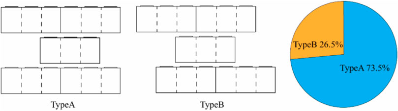
FIGURE 8. Different types of segment positional relationships between the front and last ring.
Figure 9 displays the distribution of the occurrence time of the longitudinal cracks. The current ring jacking indicates that the cracks were produced in the n-th segment when the n-th segment was jacked. The last ring jacking represents that the cracks were generated in the n-th segment when the (n+1)-th segment was jacked. The third ring jacking denote that the cracks were developed in the n-th segment when the (n+2)-th segment was jacked.

FIGURE 9. Magnitude of crack occurrence time.
Figure 9, demonstrates that more than half of the cracks were formed during the current ring jacking stage. However, unlike different from previous studies, 38% of the cracks were formed during the last ring jacking stage. Considering that 93% of the cracks were formed in the current and last ring jacking stages, this study only concentrated on the cracks developed in these two jacking stages.
3.2 Statistical analysis of segmental cracks
Since the segment cracks were primarily longitudinal, the main causes of the segment cracks were considered to be the same. Previous studies have linked formation of cracks to the thrust, torque, jacking speed, and posture of the shield machine. Therefore, the values of these tunneling parameters were utilized to analyze the causes of cracks. The equation for calculating the shield attitude adjustment could be given as:
where Δ is the adjustment amount of the shield attitude between two segment rings;
The average shield thrusts and cutter torques of the segments with and without cracks are indicated in Figure 10A. It can be seen that the average thrusts and cutter torques of the segments with cracks were lower than those without cracks, demonstrating that excessive thrusts and cutter torques were not the main causes of cracking in the segments.
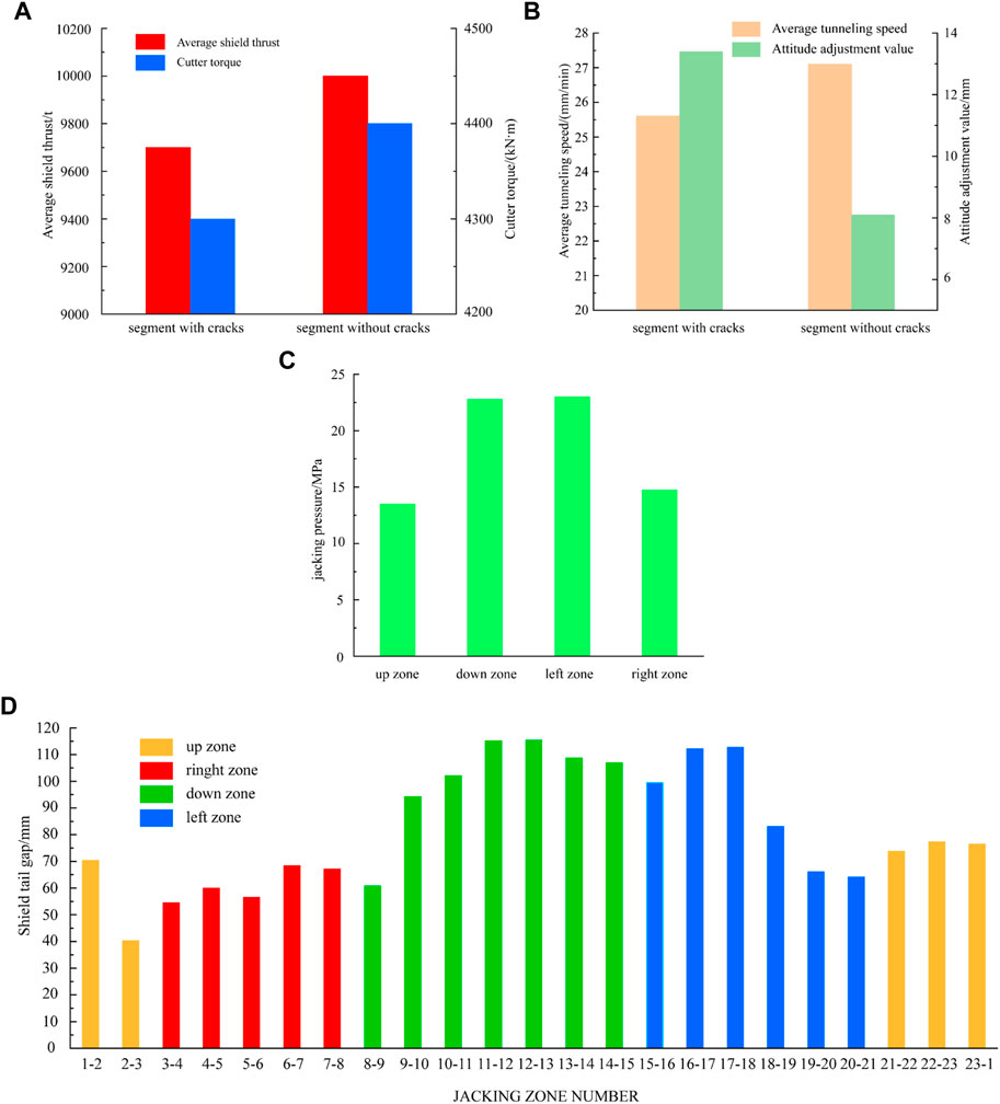
FIGURE 10. Statistics of (A) average shield thrust and cutter torque (B) average tunneling speed and attitude adjustment value (C) jacking pressure of each zone (D) Average value of shield tail clearance.
The average tunneling speeds and attitude adjustment values of the segments with and without cracks are displayed in Figure 10B. It is indicated which shows that the average tunneling speed for the segments with cracks were lower than those without cracks. Hence, the large tunneling speed was not the main cause of cracking in the segments. However, the attitude adjustment value of the segments with cracks was 1.64 times higher than that without cracks, implying the attitude adjustment of the shield machine may be the cause of cracking in the segments.
For an individual segment ring, the jacking pressure in different zones and the shield tail clearance may cause cracks in the segments. As can be seen from Figure 10C, the largest average jacking pressure was found in the down and left zones. Excessive jacking pressure may have contributed to the cracking in the segments as the cracks in the down and left zones accounted for 76% and 16% of total cracks, respectively.
It can be seen from Figure 10D that the lower and left zones of the jacks with larger shield tail clearance values had a greater proportion of cracks compared to the up and right zones, indicating that the shield tail clearance was not the cause of cracking in the segments.
4 Numerical simulation
The above analysis suggested that the adjustment of the shield attitude and the high jacking pressure in the down and left zones may be the two main causes of the longitudinal cracks in the shield segments of the Karnapuri River in Bangladesh. However, the above analysis can only reflected the correlation between the parameters and crack formation but failed to identify the mechanisms of the cracking. Moreover, investigation on cracks caused by poor assembly were not involved. Therefore, in this section, numerical simulations were performed to further analyze the causes of longitudinal cracks in the segments.
4.1 Finite element model
The analysis from the data in the previous sections, the B4 segment had the largest number of cracks. The positional of the segment ring with cracks and its front and rear rings was Type-A. Moreover, most cracks occurred in the current and the last ring jackings stage. Therefore, these two rings containing B4 segments were chosen for the further study. The n-th segment was divided into B3n, B4n, and B5n, while the (n+1)-th segments was divided into B3n+1 and B4n+1.
Figure 11 illustrates the finite element model constructed in this study. In order to simulate the interactions between the segments, circumferential pedestals were built for B3n, B5n, B3n+1, and B4n+1, and longitudinal pedestals were created for B3n, B4n, and B5n. For the B4n segment, there were two longitudinal pedestals, S and H, to simulate the uneven longitudinal support and assembly angles of the segments. Guide bars were set on the outer arc surfaces of the segments. Longitudinal bolts were adopted for the longitudinal and circumferential joints of the segments, and the clearance between the bolt and bolt hole was neglected. The handholes were simplified to be of a rectangle cross section. Steel rebars were placed in the segments of B4n, B3n+1, and B4n+1. In the numerical model, the solid elements were employed to simulate segments, bolts and pedestals, while the Truss elements were utilized to simulate the steel rebars (Zhang LB. et al., 2023a; Zhang JC. et al., 2023b).
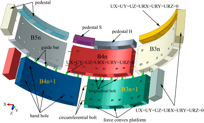
FIGURE 11. Numerical model and boundary conditions.
The pedestals and guide bars were fully constrained, and Coulomb friction was assigned between the longitudinal and circumferential joints, as well as between the segments and the guide bars. The coefficient of friction was 0.5 between the longitudinal and circumferential joints (Zhang et al., 2021), and was 0.2 between the segments and the guide bars. The steel rebars and bolts were embedded in the model (Li et al., 2023).
The model was run in three phases (Figure 12). In the first phase, the n-th segment was jacked. The (n+1)-th segment and the corresponding bolts in the longitudinal and circumferential joints were not activated. In the second phase, the (n+1)-th segment was just assembled and was about to be jacked. In the third phase, the jacking of the (n+1)-th segment was completed, and the n-th segment was thrust out from the shield tail.
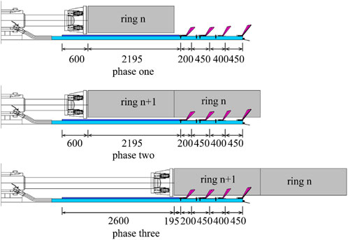
FIGURE 12. Calculation phase.
The loads applied to the segment are depicted in Figure 13. The designed pre-tightening forces of the longitudinal, and the circumferential bolts were 150 kN and 100 kN, respectively. The calculated handhole stresses of the longitudinal and circumferential bolts were 12.9 and 8.6 MPa, respectively. The jacking pressures in the down and left zones were similar, and the same was true for up and right zones, so the average pressures in the down zone (i.e., 23 MPa) and the up zone (i.e., 14.5 MPa) were taken as the jacking pressures. When the shield tail clearance was 110 mm (i.e., 0.5 MPa), the pressure in the down jacking zone was taken as the shield tail brush pressure for the n-th segment of the second phase and the (n+1)-th segment of the third phase (Wei, 2021). The shield tail sealing grease was set to 0.6 MPa based on actual practical conditions. In the third phase, when the n-th segment was thrust out from the shield tail, and the water and soil pressure of 0.45 MPa was at its maximum for the duration of the shield construction.
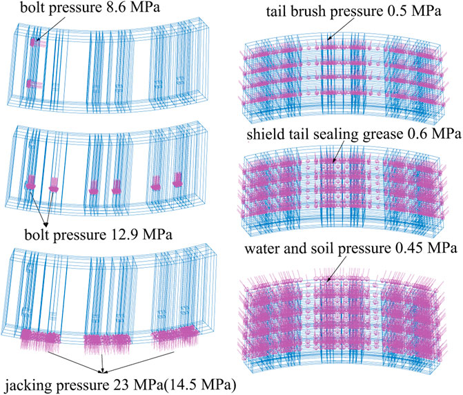
FIGURE 13. Loads applied to each segment.
The above analysis confirmed that the shield attitude adjustment and poor assembly were two possible causes of the segment cracks, and they were which therefore selected for the further analysis. Attitude adjustment may cause jack eccentricity and deflection of the jack, while the transform platform lead to a 32-mm eccentricity of the boot (Figure 2B). Hence, the additional eccentricity was not studied. Six deflection angles (0°–5°) were studied in the sensitivity analysis of attitude adjustment. The distances between the segment and the guide bar in three cases were varied between 0 mm and 8 mm (Figure 14A). The clearance in the longitudinal and circumferential joint was not considered in the sensitivity analysis of attitude adjustment.
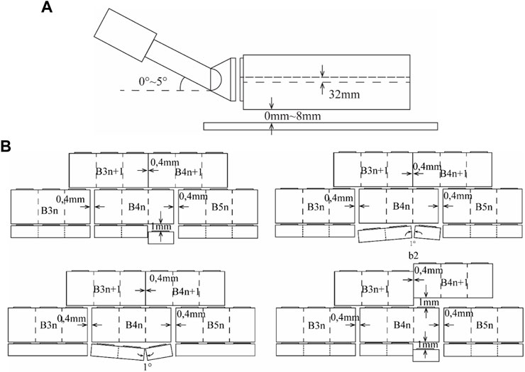
FIGURE 14. Simulation of (A) attitude adjustment and (B) inaccurate assembly.
The assembly quality was reflected by the uneven longitudinal supports and V-shaped openings of the longitudinal joints. The uneven longitudinal support was at a distance of 1 mm, and the assembly angle of the longitudinal joint was 0.1°. The assembly clearance values of circumferential joints ranged from 0 to 4 mm. In this study, assembly clearance values of 0 and 4 mm were investigated. As shown in Figure 14B, the simulation scenarios included the uneven longitudinal support, V-shaped longitudinal opening, inverted V-shaped longitudinal opening, and continuous uneven longitudinal support. The jack pressures for the shield attitude adjustment conditions were set at 23 and 14.5 MPa, respectively. The jack deflection was not considered in the sensitivity analysis of assembly condition, while the jacking pressure was fixed at 23 MPa, and the distance between the segment and the guide bar was kept at 50 mm.
4.2 Constitutive model and parameters
Although concrete damage is not necessarily manifested in the form of cracks, damage evolution is a precondition for the development of the cracks (Behnam et al., 2018). Hence, the concrete damage plasticity (CDP) model was introduced to evaluate crack development. When the tensile damage coefficient
The stress-strain relationship of concrete under compression is determined by Eqs 2–6 (China Architecture and Building Press, 2010).
In the equations,
The stress-strain relationship of concrete under tension is determined by Eqs 7–10 (China Architecture and Building Press, 2010).
where
Due to the linear stress-strain relationship of concrete in CDP, which is inconsistent with the specifications, it is necessary to manually set the yield points of concrete under compression and tension. If the yield points of tension and compression are set to
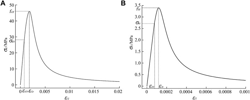
FIGURE 15. (A) Compressive stress-strain curve for concrete (B) tensile stress-strain curve for concrete.
Once the modified stress-strain curve of concrete is obtained, the tensile damage factor and compression damage factor of concrete can be calculated based on the energy loss (Krajcinovic and Lemaître, 1007) as shown in Table 1.
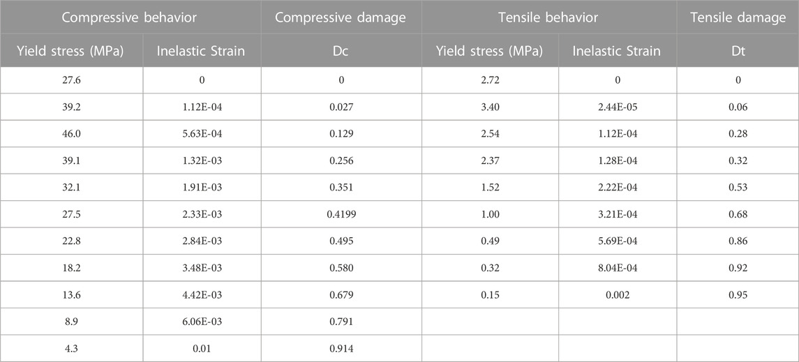
TABLE 1. Constitutive model parameters of concrete.
The elastic modulus and Poisson’s ratio of the concrete were taken as 36 GPa and 0.2, respectively. , and the concrete Poisson’s ratio was 0.2. Reinforcement and bolts adopted a double-line constitutive law. The elastic modulus and the Poisson’s ratio of steel were 206 GPa and 0.31, respectively. The yield stress and plastic strain of the steel rebars and bolts are displayed in Table 2. The CDP model was adopted to describe the B4n, B4n+1, and B3n+1 segments. The elastic concrete model was applied to B5n, B3n, and the pedestals. A steel elastic model was assigned to the guide bars.
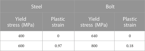
TABLE 2. Constitutive model parameters of steel and bolt (Wang et al., 2021).
4.3 Results and analyses
As segmental cracks could only be observed inside the tunnel, the analysis in this section concentrated on the cracks occurred on the segment inner surface. Figure 16 illustrates the damage results of the B4n segment in the first phase under various shield attitude adjustment conditions. The DAMAGET threshold for crack occurrence was defined as 0.95. Two major tensile cracks occurred in all the studied scenarios regardless of the deflection angle, while the crack lengths increased with the increasing deflection angle. Figure 17 shows the influence of the spacing between the guide bar and segment as well as the and deflection angle on the crack length.
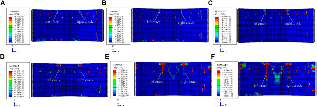
FIGURE 16. Damage of B4n, jack pressure of 23 MPa, 8 mm between guide bar and segment, deflection angle: (A) 0° (B) 1° (C) 2° (D) 3° (E) 4° (F) 5°.
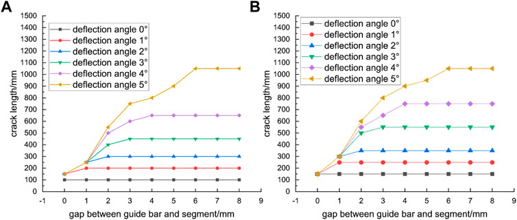
FIGURE 17. Crack lengths with different segment clearances and deflection angles, jack pressure of 23 MPa (A) left crack (B) right crack.
When the jack deflection was 0°, the crack length remained constant regardless of the spacing between the guide bar and the segment, which was caused by the eccentricity of the platform. There was an upper limit to the crack length for each case of deflection angle. This was due to the outward bending moment of the segment induced by the jack deflection. Since the outer surface of the segment was constrained by guide bars, the segment did not deform towards the outer arc surface, thus preventing positive cracks from occurring. However, the restraining effect of guide bars was weakened when the distance between the outer arc surface of the segment and the guide bars became larger. The segment was constrained by the adjacent segments and bolts. On the other hand, the formation of cracks was inhibited when the spacing between the guide bar and the segment was small enough to restrain the deformation.
Figure 18 presents the crack lengths in three phases, where the positive cracks in the B4n segment caused by the jack deflection did not develop in the second and third phases. Therefore, the positive cracks caused by jack deflection mainly occurred during the current ring jacking stage, and subsequent tunneling contributed little to the development of positive cracks.
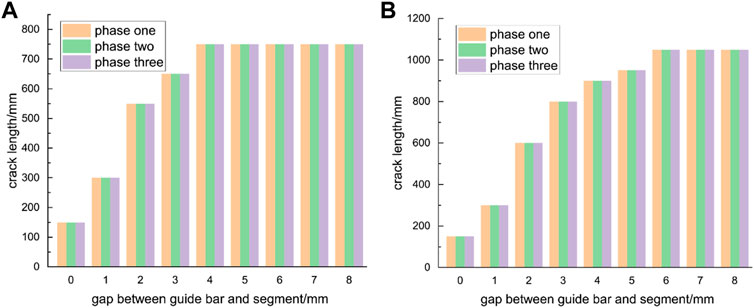
FIGURE 18. Crack lengths in the three phases with deflection angles of (A) 4 and (B) 5°.
As shown in Figure 19, the crack lengths decreased significantly when the jacking pressure was 14.5 MPa, and the positive cracks were no longer obvious when the jack deflection angle was less than 3°.
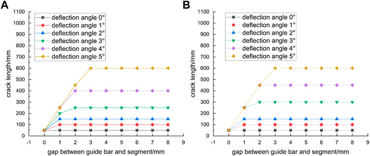
FIGURE 19. Crack lengths with different segment spacings and deflection angles, with jack pressure of 14.5 MPa (A) left crack (B) right crack.
Figure 20 presents the simulation results of a single-ring segment with the presence of uneven longitudinal support. When the assembly clearance was 0 mm, the right end of the B4n segment was deformed in the negative Z-axis direction during the jacking of the n-th segment, causing the tension on the end face and the formation of positive tensile cracks. Moreover, due to friction of the right-side segment and the constraint of the bolts, there was shear at the rear end of the uneven support, which resulted in backward shear cracks. During the jacking of the (n+1)-th segment, the positive cracks did not propagate, the length of the backward crack increased by 150 mm, and there were no cracks in the B3n+1 and B4n+1 segments. All cracks were formed in the current jacking stage, and the total number of cracks was 2. When the assembly clearance was 4 mm, the maximum length of the positive cracks was 600mm, which was an increase of 350 mm compared to the case of the tense assembly model. Meanwhile, during the last ring jacking stage, two positive tensile cracks developed on B4n+1, one backward shear crack developed on all B4n, B3n+1, and B4n+1 and one circumferential tensile crack developed on both B4n and B4n+1 the total number of cracks increased to 14.
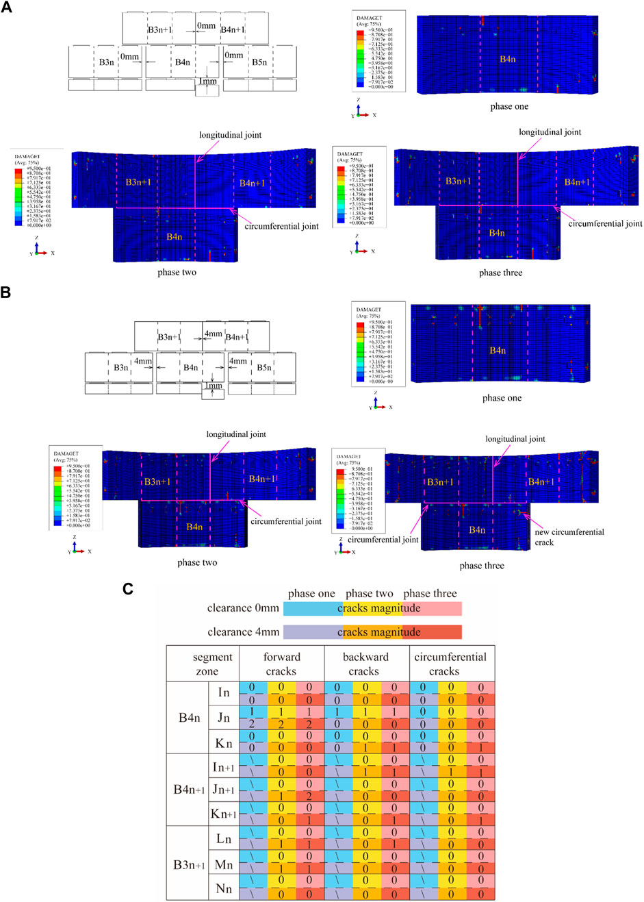
FIGURE 20. Formation of cracks due to longitudinal dislocation: (A) S pedestal dislocation with a longitudinal assembly clearance of 0 mm and (B) S pedestal dislocation with a longitudinal assembly clearance of 4 mm (C) cracks magnitude of longitudinal dislocation.
Figure 21 shows the results of a single-ring segment with a V-shaped opening in the longitudinal joint. When the assembly clearance was 0 mm, the front end of B4n was under tension during the jacking of the n-th segment. Consequently, a positive tensile crack formed in the middle segment. The left end of B4n was subjected to the friction from the adjacent segment and the constraint from the bolts during deformation, which resulted in a circumferential tensile crack. During the jacking of the (n+1)-th segment, there was a clearance between B4n and pedestal H, and the left end of B4n continued to deform in the negative Z-axis direction. Due to frictional constraint at the left end, the length of the circumferential crack increased by 300 mm, and a new backward shear crack generated at the rear of B4n. The total number of cracks was 9. When the assembly clearance was 4 mm, the both ends of B4n were only constrained by the bolts, and the deformed in the negative Z-axis direction and were in contact with pedestals S and H. The maximum length of the positive cracks was 850mm, whereas in the tense assembly model the length was only 300 mm. Meanwhile, during the last ring jacking stage one positive tensile crack developed on B4n+1, one backward shear crack developed on B4n+1, two backward shear crack developed on B3n+1, and one circumferential tensile crack developed on B4n, the total number of cracks increased to 18.
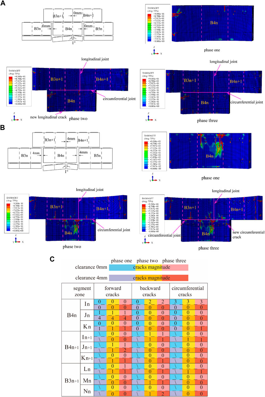
FIGURE 21. Formation of cracks due to V-shaped longitudinal joint: (A) S and H pedestals with inverted V-shapes and a longitudinal assembly clearance of 0 mm and (B) S and H pedestals with inverted V-shapes and a longitudinal assembly clearance of 4 mm (C) cracks magnitude of longitudinal joint V-shaped.
Figure 22 presents the results of a single-ring segment with an inverted V-shaped opening in the longitudinal joint. When the assembly clearance was 0 mm, B4n was a simply supported beam that was restrained at both ends during the jacking of the nth segment. The rear end was under tension, so that multiple longitudinal shear and tensile cracks formed in the middle part of the segment. During the jacking of the (n+1)-th segment, the backward crack did not propagate and there were no cracks developed on the B3n+1 and B4n+1 segments due to the friction constraints on both ends of B4n. One positive tensile crack on B3n+1 occurred in the last ring jacking stage, and the total number of cracks was 7. When the assembly clearance was 4 mm, the length of the backward crack during jacking of the n-th segment was 250 mm longer than that when the assembly clearance was 0 mm due to the lack of friction constraints. The maximum length of the backward tensile crack was 1300 mm, while in the tense assembly model the length was 700 mm. Meanwhile, one positive tensile crack on B3n+1 and two backward shear cracks on B4n formed in the last ring jacking stage, the total number of cracks increased to 12.
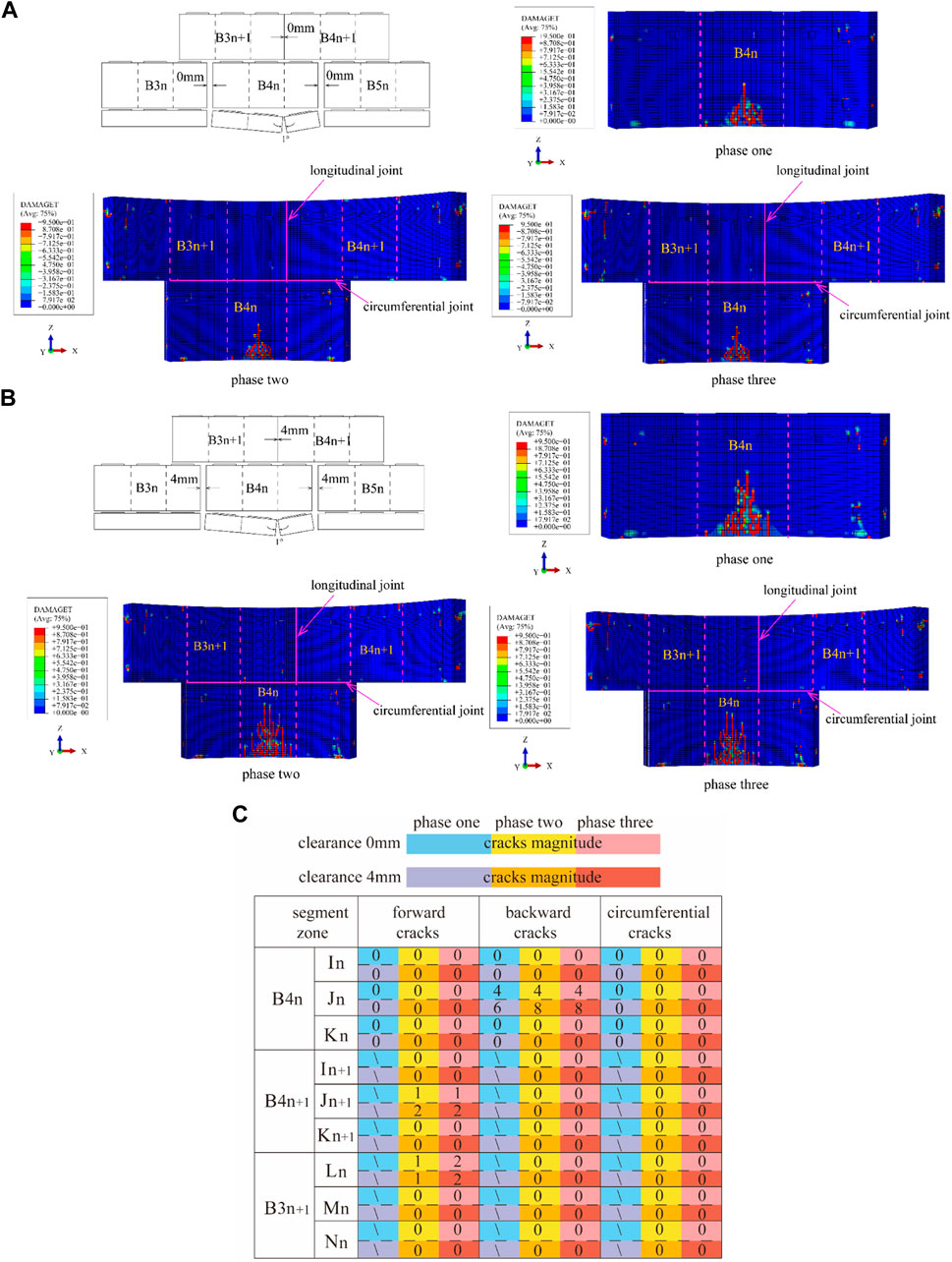
FIGURE 22. Formation of cracks due to longitudinal joint with inverted V-shape: (A) S and H pedestals with inverted V-shapes and a longitudinal assembly clearance of 0 mm and (B) S and H pedestals with inverted V-shapes and a longitudinal assembly clearance of 4 mm (C) cracks magnitude of longitudinal joint with inverted V-shape.
Figure 23 shows the segment cracks formed due to the continuous uneven support. Compared with Figure 20, when the assembly clearance was 0 mm, the front and rear rings on the right end of B4n were not sufficiently restrained during the jacking of the (n+1)-th segment. The pressure on the segment led to the shear on the uneven platform and a new backward shear crack was formed. The left end of B4n+1 was deformed in the negative Z-axis direction, and one backward shear crack was generated due to the friction of the B3n+1 segment and the constraint of the bolts. One backward shear crack on B3n+1 occurred in the last ring jacking stage and the total number of cracks was 7. When the assembly clearance was 4 mm, the maximum length of the positive tensile crack was 500 mm, while in the tense assembly model the length was 200 mm. Meanwhile, one positive tensile crack developed both on B3n+1 and B4n+1, and one circumferential tensile crack developed on B4n in the last ring jacking stage, the total number of cracks increased to 12.
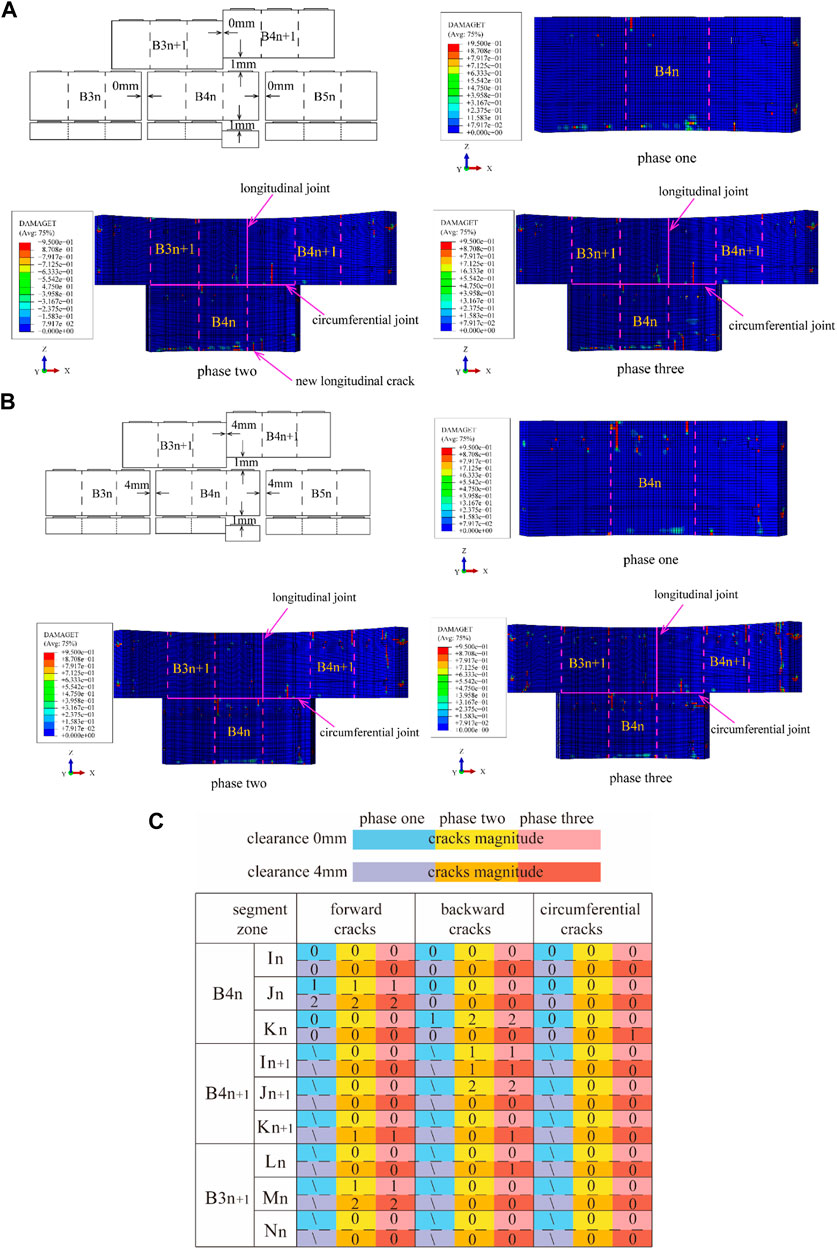
FIGURE 23. Formation of cracks due to serial longitudinal dislocation: (A) S pedestal and B4n+1 dislocation with a longitudinal assembly clearance of 0 mm and (B) S pedestal and B4n+1 dislocation with a longitudinal assembly clearance of 4 mm (C) cracks magnitude of serial longitudinal dislocation.
5 Discussion
The deviation angle of the hydro-cylinder can cause damage and cracks to the pipe segments (Mohtadinia et al., 2020; Dai et al., 2022). Dai et al. (2022) mainly focused on segment damage caused by incorrect assembly angles during the assembly process, which mainly occurs at the joints and is different from the simulated working conditions in this article. Mohtadinia et al. (2020) suggest that when the cylinder deflection angle is 5°, cracks will appear when the cylinder thrust reaches over 5 MPa, and the cracks are mainly distributed in the middle of a single pipe segment, which is consistent with the crack distribution in the numerical simulation results of this paper. The present work considers the constraint effect of the guidance bar on the pipe segment, and one should note that the front cracks generated by the hydro-cylinder deflection angle only occurred in the pushing stage of the current ring. This is consistent with the statistics of crack characteristics, where 53% of cracks were generated in the pushing stage of the current ring. This indicates that the hydro-cylinder deflection angle is one of the main reasons for cracks during tunnel construction. The cracks caused by the deviation angle are mainly affected by the radial component force generated by the hydro-cylinder force, so they have no direct correlation with the total thrust force. According to the statistical results, the adjustment amplitude of the shield tunnelling posture of the segment with cracks is greater than that of the segment without cracks, indicating that the angle between the hydro-cylinder and the segment during the pushing process is highly likely caused by posture adjustment, and the angle adjusted by posture is likely to exceed 3°. In the vast majority of cases, the clearance between the shield tail was above 50 mm, and the value of the clearance cannot reflect the contact between the pipe segment and the guidance bars. Therefore, there is little correlation between the occurrence of cracks in the pipe segment and the clearance between the shield tail.
When the quality of pipe segment assembly is poor, front cracks, back cracks, and circumferential cracks will occur, and these cracks will expand in the subsequent construction process. This is consistent with Krahl et al. (2021) conclusion that splitting, peeling, back cracks, and cracks at longitudinal joints will occur when the longitudinal assembly is staggered [ (Plizzari and Tiberti, 2007; Krahl et al., 2021),43]. However, Krahl et al. (2021) only analyzed the working conditions during the longitudinally staggered assembly of the current ring during the pushing stage, without analyzing the cracks caused by other poor assembly quality modes and the impact of subsequent construction stages on these cracks. In addition, they did not consider the assembly clearance of longitudinal joints and bolts [43]. Some cracks caused by poor assembly quality did not appear during the pushing stage of the current ring but appeared during the pushing stage of the adjacent ring, accounting for 38% of its cracks. In addition, the length, type, and quantity of cracks caused by poor assembly quality of adjacent segments are related to the constraints between segments.
Among all types of pipe segments, the K block has the least number of cracks, which may be due to the smaller arc length of the K block compared to adjacent blocks and standard blocks. The constraints of both sides and adjacent ring bolts make it difficult for the K block to be affected by the hydro-cylinder. In addition, most assembly points are selected when the K block is located in the upper half of the tunnel, where the hydro-cylinder force is relatively small. The cracks generated after the segment detaches from the shield tail only account for 7% of the total number of cracks. This is because, under the action of water and soil pressure, the axial force on the segment increases, and the clearance between the longitudinal joints of the segment decreases. Compared to being located inside the shield machine, detaching from the shield tail increases the stiffness of the longitudinal joints of the segment and decreases the pushing force of the cylinder on the segment (SHI et al., 2021).
6 Conclusion
Previous studies regarding shield tunnel cracks usually neglect the formation time of crack, stage of crack propagation and their influence by assembly clearance. In this study, based on the crack characteristics collected during a boring process, cracks caused by jacking deflection and assembly defects were investigated via sensitivity analyses of tunneling parameters and a continuous construction 3D finite element model. The length, number, propagation and occurrence time of cracks were discussed considering TBM constraints on segments and the different longitudinal assembly clearances. The following conclusions are obtained:
1) The cracks in the shield tunnel segments were dominated by longitudinal cracks, which were mainly distributed in the lower and left zones of the jacks. For each segment, the highest proportion of cracks appeared in the middle part. And 53% of the cracks were formed during the current ring jacking stage, while 40% of the cracks occurred during the last ring jacking stage.
2) The constraints on both sides of the segment and the outward jacking deflection angle led to an uneven outward deformation in the segment. Two positive cracks were formed in the middle part of the segment during the current ring jacking stage, and their lengths remained constant during the subsequent construction process. The crack formation was suppressed when the distance between the guide bar and the segment was small enough to restrain the deformation. The crack length was directly related to the magnitude of the jacking force and deflection angle.
3) Assembly defects led to positive, backward and circumferential cracks, and most cracks propagated during the subsequent construction process. A proportional of cracks were formed in the last ring jacking stage rather than the current ring jacking. The inverted V-shape longitudinal joint with an was the most severe assembly defect, which caused dense backward cracks in the middle part of B4 segment. The V-shape or inverted V-shape longitudinal joint should be avoided during construction.
4) Lateral constraints on segments suppressed the cracks generation and their length developed. The 4 mm longitudinal assembly clearance resulted in more than two times the average number and length of crack for all assembly defects compared to seamlessly assembled longitudinal joints. Considering that the longitudinal joints were compressed under water and Earth pressure, only 7% of the segment cracks occurred after the segment detached from the shield tail.
Data availability statement
The original contributions presented in the study are included in the article/supplementary material, further inquiries can be directed to the corresponding author.
Author contributions
RY: conceptualization, methodology, formal analysis QK: writing—Original draft MR: writing- reviewing and editing FJ: data curation DL: numerical simulation. All authors contributed to the article and approved the submitted version.
Conflict of interest
Authors RY, QK, MR, FJ, and DL were employed by the company CCCC Second Harbour Engineering Co., Ltd.
Publisher’s note
All claims expressed in this article are solely those of the authors and do not necessarily represent those of their affiliated organizations, or those of the publisher, the editors and the reviewers. Any product that may be evaluated in this article, or claim that may be made by its manufacturer, is not guaranteed or endorsed by the publisher.
References
Ahmadi, M. H., and Molladavoodi, H. (2019). A micromechanical sliding damage model under dynamic compressive loading. Period. Polytech. Civ. Eng. 63 (1), 168–183. doi:10.3311/PPci.13249
Behnam, H., Kuang, J. S., and Samali, B. (2018). Parametric finite element analysis of RC wide beam-column connections. Comput. Struct. 205, 28–44. doi:10.1016/j.compstruc.2018.04.004
Burgers, R., Walraven, J., Plizzari, G. A., and Tiberti, G. (2007). “Structural behavior of SFRC tunnel segments during TBM operations,” in World tunnel congress ITA-AITES (London: Taylor & Francis), 1461–1467.
Cavalaro, S. H. P., Blom, C. B. M., Walraven, J. C., and Aguado, A. (2011). Structural analysis of contact deficiencies in segmented lining. Tunn. Undergr. Space Technol. 26 (6), 734–749. doi:10.1016/j.tust.2011.05.004
Cavalaro, S. H. P. (2009). Evaluación de aspectos tecnológicos en túneles construidos con tuneladora y dovelas prefabricadas de hormigón. Barcelona, Spain: Dissertation, Universidad Politécnica de Cataluña.
Chen, J. S., and Mo, H. H. (2009). Numerical study on crack problems in segments of shield tunnel using finite element method. Tunn. Undergr. Space Technol. 24 (1), 91–102. doi:10.1016/j.tust.2008.05.007
China Architecture and Building Press, (2010). GB50010 code for design of concrete structures. Beijing, China: China Architecture and Building Press.
Dai, Z., Li, P., Wang, X., Liu, J., Fan, J., and Kou, X. (2022). Asymmetric force effect and damage analysis of unlooped segment of large diameter shield under synchronous propulsion and assembly mode. Appl. Sci. 12, 2850. doi:10.3390/app12062850
Gao, Y., Yu, Z., Chen, W., Yin, Q., Wu, J., and Wang, W. (2023). Recognition of rock materials after high-temperature deterioration based on SEM images via deep learning. J. Mater. Res. Technol. 25, 273–284. doi:10.1016/j.jmrt.2023.05.271
Gruebl, F. (2006). Segmental rings (critical loads and damage prevention). Int Symposium Undergr Excav Tunn.
Hemmy, O. (2001). Investigation on tunnel segments without curvature. Germany: University of Braunschweig.
Jiang, T., Wu, Z., Huang, L., and Ye, H. (2020). Three-dimensional nonlinear finite element modeling for bond performance of ribbed steel bars in concrete under lateral tensions. Int. J. Civ. Eng. 18 (5), 595–617. doi:10.1007/s40999-019-00488-1
Koyama, Y. (2003). Present status and technology of shield tunneling method in Japan. Tunn. Undergr. Space Technol. 18 (2-3), 145–159. doi:10.1016/S0886-7798(03)00040-3
Krahl, P. A., Palomo, I. I., Almeida, S. J. de C., Henrique Siqueira, G., Pinto Junior, N. de O., and Vieira Junior, L. C. M. (2021). Tolerances for TBM thrust load based on crack opening performance of fiber-reinforced precast tunnel segments. Tunn. Undergr. Space Technol. 111, 103847. doi:10.1016/j.tust.2021.103847
Krajcinovic, D., and Lemaître, J. Continuum damage Mechanics theory and application. Berlin, Germany: Springer. doi:10.1007/978-3-7091-2806-0
Li, X. L., Zhang, X. Y., Shen, W. L., Zeng, Q., Chen, P., Qin, Q., et al. (2023). Research on the mechanism and control technology of coal wall sloughing in the ultra-large mining height working face. Int. J. Environ. Res. Public Health 20 (2), 868. doi:10.3390/ijerph20010868
Li, X., Yan, Z., Wang, Z., and Zhu, H. (2015). Experimental and analytical study on longitudinal joint opening of concrete segmental lining. Tunn. Undergr. Space Technol. 46, 52–63. doi:10.1016/j.tust.2014.11.002
Liu, M. B., Liao, S. M., Xu, J., and Men, Y. Q. (2020). Analytical solutions and in-situ measurements on the internal forces of segmental lining produced in the assembling process. Transp. Geotech. 27, 100478. doi:10.1016/j.trgeo.2020.100478
Liu, S. M., and Li, X. L. (2023). Experimental study on the effect of cold soaking with liquid nitrogen on the coal chemical and microstructural characteristics. Environ. Sci. Pollut. Res. 30 (3), 36080–36097. doi:10.1007/s11356-022-24821-9
Liu, S. M., Sun, H. T., Zhang, D. M., Yang, K., Li, X., Wang, D., et al. (2023a). Experimental study of effect of liquid nitrogen cold soaking on coal pore structure and fractal characteristics. Energy 275 (7), 127470. doi:10.1016/j.energy.2023.127470
Liu, S. M., Sun, H. T., Zhang, D. M., Yang, K., Wang, D., Li, X., et al. (2023b). Nuclear magnetic resonance study on the influence of liquid nitrogen cold soaking on the pore structure of different coals. Phys. Fluids 35 (1), 012009. doi:10.1063/5.0135290
Lorenzo, S. G. (2021). In situ behaviour of an instrumented ring subjected to incipient TBM steering around a curve. Eng. Struct. 249, 113–124. doi:10.1016/j.engstruct.2021.113124
Lu, D., He, C., and Wang, S. (2017). Emergency medicine faculty are poor at predicting burnout in individual trainees: An exploratory study. J. South West Jiaot. Univ. 52, 75–78. doi:10.1002/aet2.10017
Lu, D., Sun, W., and Su, A. (2018). Statistics and analysis of cracking disease in segment lining for shield tunnel in construction stage. J. Railw. Eng. Soc. 35 (6), 59–66. doi:10.3969/j.issn.1006-2106.2018.06.012
Lubliner, J., Oliver, J., Oller, S., and Onate, E. (1989). A plastic-damage model for concrete. Int. J. Solids Struct. 25 (3), 299–326. doi:10.1016/0020-7683(89)90050-4
Mo, H. H., and Chen, J. S. (2008). Study on inner force and dislocation of segments caused by shield machine attitude. Tunn. Undergr. Space Technol. 23 (3), 281–291. doi:10.1016/j.tust.2007.06.007
Mohtadinia, M., Ahmadi, M. H., Fasaghandis, M. M., Dibavar, B. H., and Davarpanah, S. M. (2020). Statistical and numerical study of chipping and cracking in segmental lining. Period. Polytechnica-Civil Eng. 64 (3), 869–886. doi:10.3311/PPci.16037
Nogales, A., and Fuente, A. de L. (2020). Crack width design approach for fibre reinforced concrete tunnel segments for TBM thrust loads. Tunn. Undergr. Space Technol. 98, 103342. doi:10.1016/j.tust.2020.103342
Plizzari, G. A., and Tiberti, G. (2007). “Structural behavior of SFRC tunnel segments,” in FraMCos-6. Catania (Brescia, Italy: University of Brescia).
Sharghi, M., Chakeri, H., Afshin, H., and Dias, D. (2021). Analysis of the possible cracking and damages of tunnel lining segments during installing stage. Soil Mech. Found. Eng. 58, 287–294. doi:10.1007/s11204-021-09741-z
Shayanfar, M. A., Mahyar, P., Jafari, A., and Mohtadinia, M. (2017). Classification of precast concrete segments damages during production and transportation in mechanized shield tunnels of Iran. Civ. Eng. J. 3, 412–426. doi:10.28991/cej-2017-00000101
Shi, X. Y., Yao, Y., Wang, L., and Zhang, C. (2021). The influence of CDP model parameters based on the numerical simulation of uniaxial loading test. Build. Struct. 51, 999–1007.
Sugimoto, M. (2006). Causes of shield segment damages during construction. Int. Symposium Undergr. Excav. Tunn. Eff. Groundw. Tunn. Stab., 67–74.
Tian, L., Wang, X., and Cheng, Z. (2021). Numerical study on the fracture properties of concrete shield tunnel lining segments, 2021–11. doi:10.1155/2021/9975235Geofluids
Wang, F., Huang, H., Soga, K., and Li, Z. (2021). 3D modelling of concrete tunnel segmental joints and the development of a new bolt-spring model. Tunn. Undergr. Space Technol. 110, 103835. doi:10.1016/j.tust.2021.103835
Wei, L. (2021). Experimental study on mechanical behavior of wire brushes on shield tail. Tunn. Constr. 41 (2), 206–211. doi:10.3973/j.issn.2096-4498.2021.02.006
Xu, G., He, C., Lu, D., and Wang, S. (2019). The influence of longitudinal crack on mechanical behavior of shield tunnel lining in soft-hard composite strata. Thin-Walled Struct. 144, 106282. doi:10.1016/j.tws.2019.106282
Xu, M., and Zhang, Z. (2013). Cause analysis and treatment of segment damage of large diameter shield tummel. Chin. J. Undergr. Space Eng. 9, 1705–1712.
Yang, Y., Zhou, B., Xie, X., and Liu, C. (2018). Characteristics and causes of cracking and damage of shield tunnel segmented lining in construction stage–a case study in Shanghai soft soil. Eur. J. Environ. Civ. Eng. 22, 213–227. doi:10.1080/19648189.2017.1356243
Zhang, J. C., Li, X. L., Qin, Q. Z., Wang, Y. B., and Gao, X. (2023b). Study on overlying strata movement patterns and mechanisms in super-large mining height stopes. Bull. Eng. Geol. Environ. 82 (3), 142. doi:10.1007/s10064-023-03185-5
Zhang, L. B., Shen, W. L., Li, X. L., Wang, Y., Qin, Q., Lu, X., et al. (2023a). Abutment pressure distribution law and support analysis of super large mining height face. Int. J. Environ. Res. Public Health 20 (1), 227. doi:10.3390/ijerph20010227
Keywords: segment cracks, shield tunneling parameters, statistical analysis, numerical modeling, jack deflection, assembly defects
Citation: Yang R, Kong Q, Ren M, Ji F and Li D (2023) Statistical and numerical analysis on characteristics and influence factors of construction cracks of large-diameter underwater shield tunnel: a case study. Front. Earth Sci. 11:1235674. doi: 10.3389/feart.2023.1235674
Received: 06 June 2023; Accepted: 05 July 2023;
Published: 19 July 2023.
Edited by:
Xuelong Li, Shandong University of Science and Technology, ChinaReviewed by:
Chaoxuan Zhang, Chinese Academy of Sciences (CAS), ChinaCheng Lyu, Sichuan University, China
Copyright © 2023 Yang, Kong, Ren, Ji and Li. This is an open-access article distributed under the terms of the Creative Commons Attribution License (CC BY). The use, distribution or reproduction in other forums is permitted, provided the original author(s) and the copyright owner(s) are credited and that the original publication in this journal is cited, in accordance with accepted academic practice. No use, distribution or reproduction is permitted which does not comply with these terms.
*Correspondence: Rui Yang, eXJfc3dqdHVAb3V0bG9vay5jb20=