 Xiaobo Hao1*
 Xiaolou Chi
- 1Ningxia Hongdunzi Coal Industry Co., Ltd., Yinchuan, China
- 2Coal Mine Safety Mining Equipment Innovation Center of Anhui Province, Anhui University of Science and Technology, Huainan, China
Fully mechanized caving is the most popular method for safe and efficient coal mining in China. In this study, based on the geological and mining conditions of Workface 822 of the Yuandian No. 1 Mine, we used theoretical analysis and numerical simulation to analyze the crushing mechanism of gangue-containing coal seam roofs, discuss the mechanical model of stability of gangue-containing coal seams to simulate different methods and caving intervals, and optimize the caving parameters of coal from gangue-containing coal seams. The results indicated that under the action of mining-induced stress, the peak pressure on the support is less than the rupture stress of the gangue, and relying on the mine support pressure alone can promote the rupture of the roof coal. However, it is difficult to rupture the gangue in the roof; owing to the gangue-containing coal seams, the area where the damage coefficient of the roof coal at the upper end of the support is lower than 1 is further expanded from the front of the support to the entire upper area of the support, and the crushing effect of roof coal is greatly weakened. After comparing the effects of five caving modes, we finally decided to use the single-cycle interval caving mode. The minimum gangue content of Workface 822 of the Yuandian No. 1 Mine is 54.35%. The results of this study can provide a theoretical basis and experience-based reference for the safe and efficient mining of gangue-containing coal seams.
1 Introduction
Since fully mechanized caving was introduced to China in 1984, it has gradually become the primary mining method for thick coal seams and is associated with considerable economic benefits (Chen et al., 2022; Lyu et al., 2022; Nan and Wang, 2022; Song and Du, 2023). Nevertheless, such coal seams typically occur under complex conditions, making it difficult to improve the recovery rate of roof coal and reduce the gangue content. The problem has attracted much research attention, and several researchers have used the discrete element method to simulate the caving-in phenomenon (Yin et al., 2021; Si et al., 2022; Fu et al., 2023). At the same time, they also analyzed in-depth the contact force field, velocity field, shape, shifting interval, and roof coal tax rate affected by the roof coal thickness and other issues. In addition, they also examined the factors that affect the caving behavior, such as the height up to which machine mining takes place and the lumpiness of the coal rock, and formulated a theory for the fragmentation of the roof coal in fully mechanized operations (Zhou et al., 2017; Du and Song, 2022; Liu et al., 2022; Zhao et al., 2022; Lyu et al., 2023a). The release law of the low-lying fully mechanized caving roof coal is based on field observations, bulk similarity simulation tests, and other methods, and it successfully proposes a theoretical model for the flow of bulk medium (Zhang et al., 2022a; Du et al., 2023; He and Huang, 2023). It also demonstrates the release and flow processes of roof coal in the low-level fully mechanized caving link (Zhang et al., 2022b; Lyu et al., 2023b; Jiang et al., 2023).
Since thick gangue-containing coal seams have typical mechanical performance and storage characteristics (Tang and Tang., 2012; Bu et al., 2021; Yang et al., 2021; Hao et al., 2022), several researchers have studied the influence of these storage characteristics on the caving performance of roof coal (Dai et al., 2020; Tu et al., 2020). It has been concluded that the main factors that affect the caving performance include the thickness, hardness, layers, and number of layers of gangue-containing coal seams (Yang et al., 2023). In roof coal, gangue-containing coal seams can be divided into three types based on their constituent layers. The breaking characteristics of the seams depend on the thickness of the seams (Xie et al., 2020; Xie et al., 2022; Chen et al., 2023). The thick seam of roof coal is mainly in the cantilever mode and supports the upper roof, which makes it difficult for the roof coal to fall in time and causes it to remain in the goaf. If the thickness of the gangue-containing coal seam is increased, the corresponding degree of fragmentation will increase accordingly, which will not improve the crushing effect (Cui et al., 2019; Jiang et al., 2021; Shi et al., 2021). If the ultimate strength of the gangues is lower than that of roof coal, then it has better caving performance. However, if the ultimate strength exceeds that of the roof coal, then the caving performance will decrease significantly, and the old roof will increase both the strength and the interval (Liang et al., 2022; Yang et al., 2022; Lyu et al., 2023c).
The above studies are mostly aimed at the theoretical analysis of coal seam inclusion mechanics, but there has been little research on combined fully mechanized caving parameter optimization. Based on the geological and mining conditions of Workface 822 of the Yuandian No. 1 Mine, this paper analyzes the crushing mechanism of gangue coal seams from a theoretical point of view, with the help of PFC2D numerical simulation software to truly restore the working conditions of the coal seam, simulate the coal discharge step distance and coal discharge method, directly observe the coal discharge effect through the particle flow, and determine the optimal method. It has certain theoretical and field-guiding significance for the safe production of multi-coal seam fully mechanized caving faces.
2 Background
2.1 Occurrence of coal
In Yuandian No. 1 Mine, the thicknesses of Seams 81 and 82 are 1.00–3.50 and 0.80–4.90 m, respectively, with an average thickness of 2.57 and 2.66 m, respectively; the distance between the two layers is between 0.5 and 4.0 m, with an average value of 1.98 m. The lowest inclination of the coal seam is 3°, the largest is 8°, and the average value is 6°. Seam 82, which has coal located in the combustible layer, is prone to spontaneous combustion after the mining of 81 coal. This poses a significant threat to safe production. Workface 822 uses fully mechanized caving technology for mining. A high-strength mudstone with a thickness of approximately 1.98 m is situated between the two layers. The existence of hard gangues has a significant impact on the caving characteristics of roof coal (Figure 1).
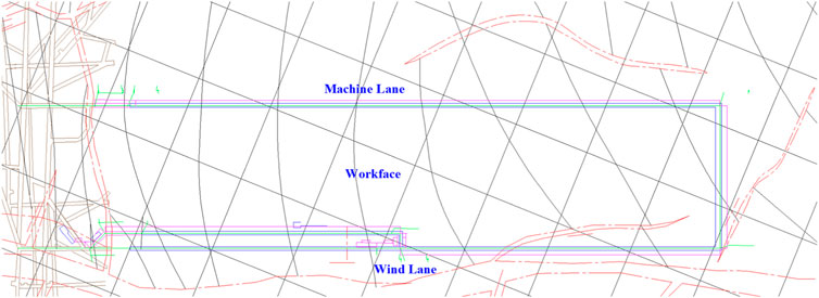
FIGURE 1. Roadway layout plan of Workface 822.
Figure 2 shows a comprehensive chart that lists the features of the different strata of Workface 822 as follows:
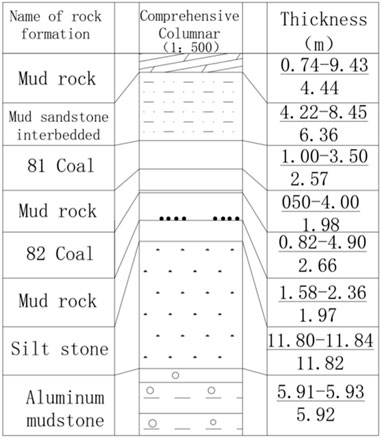
FIGURE 2. Comprehensive column chart of the stratum at Workface 822.
The immediate roof of 81 has the following features: interbedded mud-sandstone with a thickness of 4.22–8.45 m and an average value of 6.36 m; a dark gray, layered argillaceous structure, containing many root fossils, with pyrite film, fine sandstone bands, and horizontal bedding.
The old roof of 81: mudstone, a thickness of 0.74–9.43 m with an average of 4.44 m; a dark gray, muddy structure, containing many fragments of plant fossils, dense and brittle.
The seams between 81 and 82: thickness = 0.50–4.00 m, with an average of 1.98 m. The lithology is dominated by mudstone (gray-dark gray, brittle, massive, argillaceous structure containing a small amount of silt and carbonaceous material along with many plant fossil fragments), and partially siltstone (dark gray, silty structure, layered structure, interbedded with fine sandstone strips, with horizontal bedding, containing many phytochemical fragments).
The immediate floor of 82: thickness = 1.58–2.36 m, with an average of 1.97 m; a dark gray, muddy structure, dense and brittle, containing fragments of plant fossils.
2.2 Physical properties of coal rock
We selected the irregular coal rock at Workface 822 underground and processed it into the standard test block required by the testing standards. First, we placed the rock sample obtained onsite in the core drilling machine and obtained a cylinder with a diameter of 5 cm, which was cut to make cylindrical blocks of 2.5 cm, 5.0 cm, and 10.0 cm in length, respectively (Figure 3). Finally, we used a grinding machine to grind the end face of the test piece. When grinding, the non-parallelism of the two ends of the test piece should not exceed 0.001 cm, while the difference in diameter between the upper and lower ends should not exceed 0.002 cm.
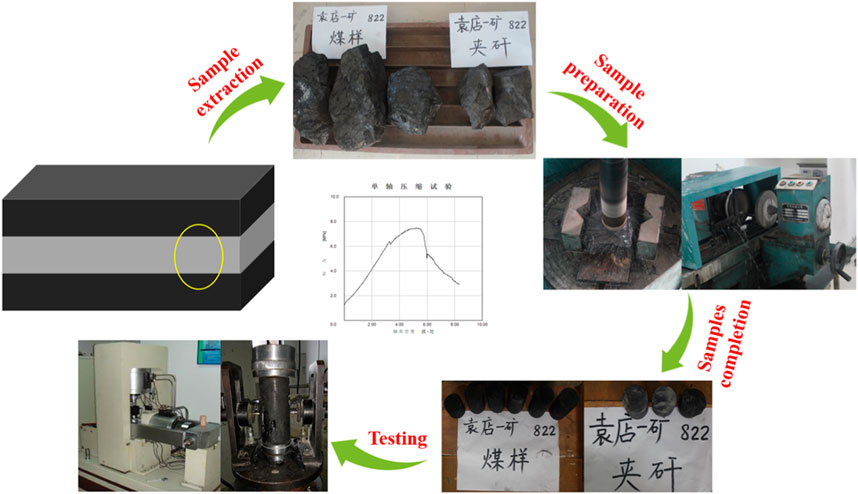
FIGURE 3. Treatment of coal rock samples collected from Workface 822.
Our tests and calculations were carried out in accordance with the requirements in the “Mechanical Performance Test Regulations for Coal and Rock Physics”. The mechanical performance test was completed using RMT equipment, thus obtaining the physical and mechanical parameters of coal rock (Table 1).
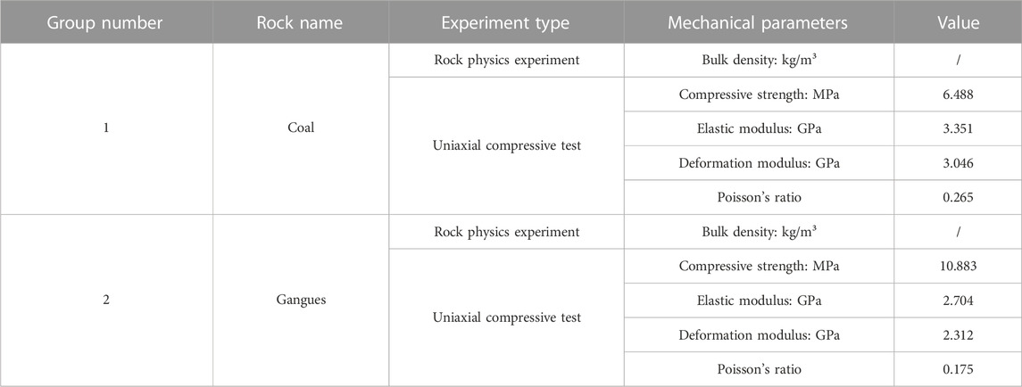
TABLE 1. Mechanical parameters of coal rocks in Workface 822.
3 Crushing mechanism of gangue-containing coal seams
3.1 Force analysis for crushing mechanism of roof coal
With the continuous advancement of the workface, the roof coal gradually transforms from the initial elastic state to the plastic state. We can characterize the conversion of continuous damage and damage in open roof coal mining by utilizing the force change characteristics of fully mechanized workface roof coal. For this reason, we subdivided the roof coal behind the stress zone of the original rock into different zones according to its stress state change (Figure 4).
(1) Area I: the area from the original rock stress area to the region of peak pressure on the advanced support. The stress in this area increases continuously, but the roof coal remains in the elastic stress state. With the continuous advancement of the workface, the support pressure continues to rise, and the three-dimensional unequal compressive stress state inside the roof coal becomes increasingly prominent, resulting in microscopic damage to the roof coal medium and the formation of certain cracks. However, macroscopic crack growth was not observed in this case.
(2) Area Ⅱ: the area between the region of peak pressure on the advanced support and the upper end of the workface wall. In this case, the stress in this area decreases, and roof coal enters the plastic limit equilibrium state. At the peak of the support pressure point, the roof coal is already in the limit equilibrium state, after which yield damage occurs and the goaf side constraint decreases, which in turn increases the speed of roof coal horizontal displacement and produces obvious plastic deformation. Additionally, the cracks in the roof coal connect and expand rapidly, resulting in eventual macroscopic rupture. Considering an infinitesimal element in this area that can be regarded as an elastic medium, its physical equation according to the state of space stress is as follows.
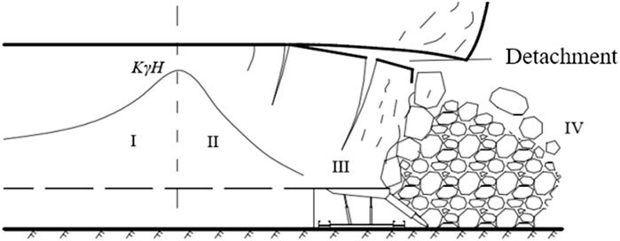
FIGURE 4. Destruction process partition of fully mechanized workface roof coal.
Assuming
Substituting the above formula into Eq 2, the following formula can be obtained:
Then, when the roof coal is in the limit state, the following fracture stress formula can be obtained:
where
Mining of the coal seam causes the support pressure to peak and, along the vertical direction, the minimum pressure is twice that of the original rock, while the maximum is four times. If the peak pressure on the support exceeds the ultimate stress of roof coal, then the roof coal will rupture and communicate with the primary fractures, so the strength of roof coal will begin to decrease and it will turn into an irregular block in advance.
According to the mechanical performance test of the coal and gangue laboratory of Yuandian No. 1 Mine, as well as field data, we set
In this case, the peak pressure on the support slightly exceeds the failure stress of the roof coal, which decreases the overall strength of the roof coal, and then transforms into an irregular block, but the crushing effect is not significant enough.
(3) Area Ⅲ: the area from the wall to loose-rupture zone. In this case, the roof coal enters the plastic limit equilibrium state, and the roof coal block also enters the structural hinge equilibrium state. The roof coal on the roof control area of the workface is not supported by the original bottom coal; rather, it gradually approaches the goaf, and with continuous support, the stress state of the roof coal changes significantly, and the vertical displacement increases rapidly. Moreover, the corresponding bedding and fractures develop significantly. Additionally, under continued support, the roof coal will loosen and rupture towards the longitudinal cracks. Since the sinking speed of the roof coal exceeds the sinking speed of the roof, delamination will occur in the region where decomposition occurs; the sinking speed of coal in the upper roof is lower than that of coal in the lower roof. The horizontal displacement speed of the roof coal on the side close to the goaf is obviously higher than that of the roof coal on the other side far from the goaf, which ensures the development of the internal separation layer of the roof coal so that the fragmentation level of the roof coal is significantly improved. In this case, the upper end of the wall and the support beam area, along with the corresponding lower roof coal, is the most fragmented. In this link, the main factors that improve the fragmentation of roof coal are the number of repeated supports and the size of the support force. In the fully mechanized mining cascading roof coal link, the roof coal is initially in a three-dimensional constant stress state. When the workface advances, the lateral constraints towards the workface begin to drop. Therefore, the roof coal in area III begins to come under the uniaxial stress state. Additionally, roof coal deformation, failure, and stress, etc., are related to the support and roof conditions.
The failure equation is mainly determined by the coal body strength and minimum principal stress parameters. If it is lower than the maximum principal stress, the coal body at the front of the support will be damaged. In this case, the “Moore-Coulomb” criterion can be used to judge the level of damage of the roof coal. If the compressive stress is positive, the criterion can be expressed using:
where YF is the damage coefficient of coal body,
When f=0, the roof coal damage coefficient can be given by:
As mentioned above, σ1 and σ3 correspond to the vertical and horizontal stresses, respectively. The higher the former, the smaller the latter, and the higher the damage coefficient. From this, we can conclude that the roof coal in region III has changed from the original three-way force to a one-way stress state, which then breaks rapidly.
(4) Area Ⅳ: this corresponds to the collapse area of the roof coal, that is, the goaf behind the support. In this case, the roof coal begins to exhibit bulk accumulation. After the support moves forward, the roof coal will crack significantly under the rotary extrusion effect of the fractured roof rock formation and its own weight. Additionally, because the upper roof coal is weaker than the lower roof coal in terms of the extent of loose fragmentation, when the coal is falling, the upper large roof coal is more likely to bear the hinge extrusion, thereby creating a balanced arch structure that restricts the release of the roof coal. If there is gangue present, then the upper roof coal will not be broken fully, resulting in larger blocks. A balanced arch structure is easier to form, so the caving rate of roof coal decreases further. During caving, the difficulty of roof coal arching is mainly affected by the roof coal fragmentation level: the higher the fragmentation level, the lower the chance of arching.
The above areas show the damage process of roof coal, among which the support pressure function of Areas I and II is more prominent, and the distribution and size are the key elements of the form and degree of damage of roof coal collapse. Hence, the advanced support pressure in the stop drives the roof coal damage. The micro- and macro-cracks produced by the primary fractures in the media and these two areas are the key factors that lead to the caving of roof coal and have a decisive impact on the fragmentation level and shape of collapse of the gangue-containing roof coal. For Area III, the continuing support will significantly affect the roof coal, with the lower roof coal being more conducive and producing a greater impact.
Assuming that the roof coal is not extremely hard and the gangue content will not affect the caving performance, the roof coal will break and collapse when it passes through the above four regions, with the collapse angle generally exceeding 60°. Therefore, the phenomenon of roof coal suspension will not occur, and large lumps of coal will rarely appear. Only scientific control of the caving process is required, and the corresponding caving rate is usually not very low.
If the hardness of the roof coal is high, the thickness of the gangue-containing coal seam is high, or more gangue-containing coal seams are involved, then the roof coal often breaks into larger pieces, and its breaking and collapse shows periodicity under the support pressure. If the gangue belongs to the middle level, then the roof coal at the upper end of this layer is blockier so that the slump angle decreases, and the lack of fluidity makes it difficult for the roof coal to be released and meet the requirements. The fragmentation level of low roof coal can meet the requirements under the continued support. Therefore, if the roof coal contains gangue, it becomes difficult to meet the requirements of roof coal collapse and crushing by using the continued support effect and mine pressure. Therefore, we also need to use some other technology to assist in crushing the roof coal, so that the roof coal can be released better.
3.2 Force analysis for crushing mechanism of gangue-containing coal seams
Before being subjected to mining action, the roof coal and gangue-containing coal seams present a three-way stress state, and the roof coal outside the peak pressure on the support area in front of the wall is in an elastic state. Within this peak region, the two layers are in different stress states. Since gangue-containing coal seams have higher hardness and strength, under the action of the continuous rise of the roof coal load above the support, the roof coal evolves into a plastic state with the appearance of the support pressure effect, thus producing a cushioning effect on the gangue, retaining the elasticity of the gangue-containing coal seams. In this case, tiny units can still be extracted from this layer, and its initial condition can be regarded as an elastic medium. According to the physical equation of the space stress state, when the gangue-containing coal seam is in the limit state, the rupture stress formula is:
where
If gangue-containing coal seams exist, combined with the practical data for the Yuandian No. 1 Mine, we can set μ’ and
Through the mining-induced stress effect, the rupture stress of gangues exceeds the peak pressure on the support, which in turn exceeds the roof coal rupture stress value. For this reason, relying on the mine support pressure effect alone can cause the roof coal alone to rupture, and it is difficult to rupture the gangue-containing coal seams contained in the roof coal. Therefore, we must use the auxiliary method to loosen and soften it, so that the crack density can penetrate and the overall strength of the roof coal can be reduced, thereby improving the caving performance of roof coal.
As
where
The peak pressure on the support is KγH, and its size reaches 31.5 MPa,
In the specific production link, that is, during the forward process of the workface, the average bulk density, lithology, and buried depth of the overburden all change dynamically. Therefore, the KγH value will also change dynamically. When the workface positions are different, gangues or roof coal have different primary fractures; the former also has lithological changes, and at the same time the corresponding strengths of
3.3 Mechanical model for stability of gangue-containing coal seams
In the deep gangue-containing coal seams of the wall, the strength of the coal body is relatively low because it has not been subjected to mining action, and the coal body is in a three-dimensional stress state when surrounded. After the workface advances, if the gangue-containing coal seams are at the upper end of the top support control area, the roof coal at the lower end of this layer will start to sink and break, and the roof coal at the upper end of this layer will sink a little after the gangues are deformed, resulting in very small direct sinkage. This causes delamination between the upper layer and its immediate roof, so the gangue-containing coal seams act as a cantilever beam. The load is assumed to be uniformly distributed as the key block of the masonry beam structure breaks when the workface moves, simultaneously rotating and staggering at the upper end of the support so that the gangue-containing coal seams are close to the area behind the support, which means that the free end of the cantilever beam bears higher stress, and the roof coal has more significant deformation that is similar to the gangue-containing coal seams on the wall side, while the fixed support end of the cantilever beam can be regarded approximately as the stress state of the original rock. Hence, the upper end of the cantilever beam can produce non-uniformly distributed linear loads.
Based on the gangue-containing coal seams, we created a broken cantilever beam model (non-uniform load) and developed the corresponding force model (Figure 5).
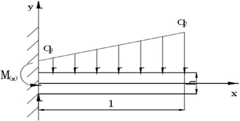
FIGURE 5. Force representation of gangue-containing coal seams under the action of non-uniform load.
Herein,
where
where K is the stress concentration factor;
Substituting Eq 11 into Eq 12, we get:
where C is the integral constant that can be specified in terms of boundary conditions. If the value of
Then:
Substituting Eq 14 into Eq 15, we get:
In the same way, based on the boundary conditions, we clarify the D integral constant:
If
Then, we get the bending moment equation of the gangue cantilever beam as:
Determining the first-order derivative of x to the bending moment equation
Further differentiating x to the bending moment equation
Substitute stationary points x1 and x2 into.
Since x2 is below 0 and above the x-axis, it is meaningless, and for this reason, the range of value of
Set
The solution to the limit thickness h of the gangue-containing coal seams is:
After sorting out, the maximum cantilever interval
According to the geological conditions of Yuandian Workface 822 and related parameters of the roof coal and gangues, where the maximum cantilever distance of the gangue-containing coal seams, thickness of roof coal, and thickness of gangue-containing coal seams are represented by l, h2, and h1 respectively, the relationship between them is observed in Figure 6.
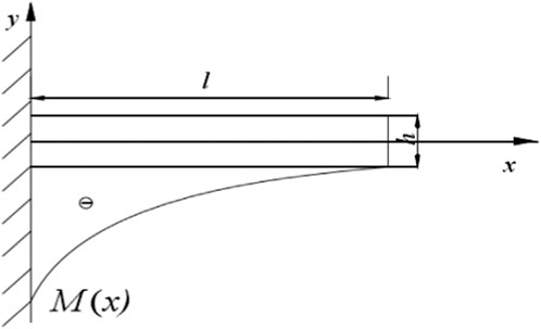
FIGURE 6. Bending moment distribution diagram of gangue-containing coal seams under non-uniform load.
Figure 7A shows the linear relationship between l and h1 when the thickness of the roof coal at the upper end of the gangues is approximately 2.6 m. According to this curve, it can be concluded that l shows a parabolic growth trend when the thickness of the gangue-containing coal seam is increased, but the curvature is small. When the value range of h1 is 1–2 m, the value of l is between 1.5–3.2 m.
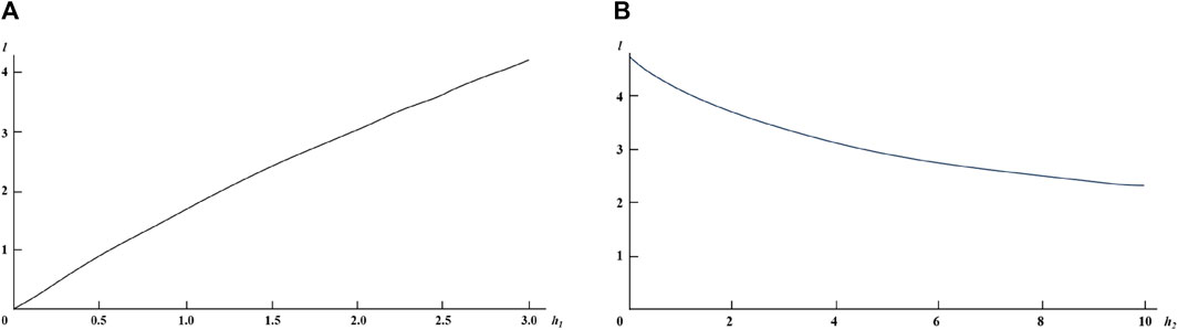
FIGURE 7. Linear relationship between cantilever limit span l and h1, h2 coal (A) Maximum cantilever distance and thickness of gangue-containing coal seam 2D linear relationship; (B) maximum cantilever distance and roof coal thickness 2D linear relationship.
Figure 7B shows the linear relationship between the thickness of the gangue-containing coal seam at 1.98 m and the non-uniform load, l, and the thickness of the roof coal at the upper end of the gangues. This curve indicates that, when the thickness of h2 increases, l presents a state of negative exponential curve reduction, and the degree of reduction is gentle.
Under non-uniform load (Figure 7).
(1) When the thickness of the roof coal at the upper end of the gangues reaches a certain level, the maximum suspension distance of the gangue cantilever beam increases in thickness and the maximum overhang distance becomes increasingly parabolic, while the curvature is small. When the thickness of gangue-containing coal seam is fixed, an increase in the upper roof coal thickness will result in a decrease in the corresponding maximum cantilever distance with a negative index, and the decrease is very small.
(2) The upper roof coal of gangue-containing coal seams and the thickness of gangue-containing coal seams are typical factors that have an impact on the layout of the maximum suspension of the cantilever beam. Based on the shape of the curve, gangue-containing coal seams have a greater influence on their own thickness.
(3) Yuandian No. 1 Mine’s gangue-containing coal seams have an average roof coal thickness of 2.57 m. In this case, as the thickness of the gangue-containing coal seam increases, l presents a parabolic growth with a small curvature, which can be approximately regarded as a straight line with a slope of 1.5 If the thickness of the gangue-containing coal seam reaches 1 m and 2 m, the corresponding span l is 2 m and 3.2 m, respectively. If the thickness of the gangue-containing coal seams is 1.98 m and is in a fixed state, then l shows a negative exponential decline with an increase in the roof coal thickness at the upper end of the gangue-containing coal seams. If the roof coal thickness is 1 m, 3 m, and 5 m, respectively, the span l in this case is 4.2 m, 3.5 m, and 3.0 m, respectively. Due to the effect of the non-uniform load, the effect of gangue-containing coal seams on l is not obvious.
Based on the theoretical and actual situations of the caving workface, and after clarifying the caving interval, we referred to the following empirical formula:
where L and h3 are the caving interval and vertical elevation of the top of the coal seam and the cave opening, respectively, m.
It can be calculated that the caving interval is approximately 0.78 m, which is less than the maximum cantilever interval.
4 Numerical simulation of combined fully mechanized caving process
4.1 Model building
Considering the geological and production conditions of Workface 822 of Yuandian No. 1 Mine as the background, we used the PFC2D two-dimensional particle flow numerical calculation method to study the influence of different caving intervals and caving modes on the release law of roof coal. We constructed gangues and roof coal into a two-dimensional mechanical model that can be numerically analyzed. The yellow particles in the figure represent gangues, the black particles represent coal seams, and the rest represent roof gangues. The length and height of the model are 15 m and 12 m, respectively. According to the requirements, based on its vertical direction, we built a 2 m gangue, a 3 m coal seam, and a 6 m roof from bottom to top (Figure 8A). The coal rock physical and mechanical parameters in the model are shown in Table 2.
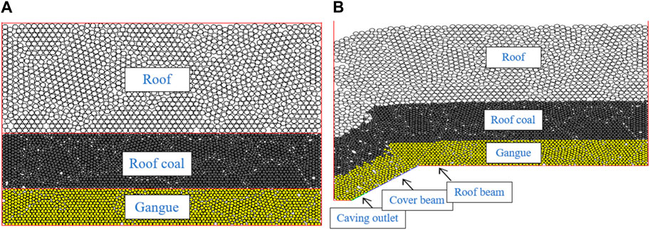
FIGURE 8. Initial numerical model. (A) Model building; (B) model preparation.
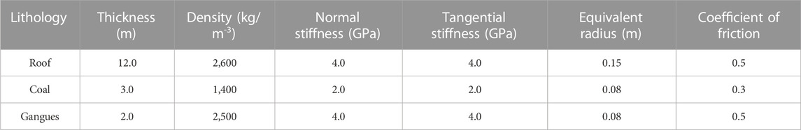
TABLE 2. Workface 822 coal rock physical and mechanical parameters.
This model simulates the caving process. Therefore, we did not consider the coal cutting effect in the modeling. Hence, when modeling, we regarded the gangues as the beginning, and the sides and bottom of the model were modeled as nested walls in the program, which can carry and fix solid particles. When running the model, the program successively removed the wall to the same length as the caving interval and the bottom of the model, simulated the caving opening, and automatically considered a wall at a 40-degree angle with the horizontal plane to simulate the support shield beam. The caving opening was closed when the roof gangue caving opening was encountered, and the release of coal was assumed complete. Then, the support moved forward for a caving interval and the program proceeded to release coal in a subsequent cycle. When the caving opening moved forward, the program also needed to consider the coal seam floor wall. The vertical distance between this wall and the roof coal was consistent with the machine mining height, both of which were 2.5 m. The purpose was to ensure that the onsite caving space was consistent with the workface caving space (Figure 8B).
The breaking and moving laws of the top coal in the fully mechanized caving face were studied and the reasonable coal setting process parameters based on the laws and characteristics found, so as to improve the recovery rate of coal resources. The influence of the coal-drawing step distance and coal-drawing method on the characteristics of top-coal caving was analyzed, and, in combination with the specific geological conditions of the 822 working face, reasonable coal-drawing process parameters are put forward.
4.2 Simulation of combined fully mechanized caving based on the interval
During practical fully mechanized caving, the caving interval can only be multiplied with the cutting depth of the shearer. Therefore, to carry out comparative analysis, we introduced three simulation schemes, and set the caving interval as follows: ①‘one mining, one caving’; ② ‘two mining, one caving’; ③ ‘three mining, one caving’. The corresponding caving intervals were 0.6, 1.2, and 1.8 m, respectively.
Based on the above scheme, PFC2D performed real-time simulation on the continuous propulsion link of the support, showing the movement and release of the roof coal. The method of “closing the window when encountering gangue” can control the gangue content precisely, but it will have an effect on the recovery rate. For this reason, in the simulation, the simultaneous appearance of two roof particles at the caving opening were used as the principle to close the caving opening, and then we simulated and calculated the caving rate of roof coal situation based on this. To compare indicators such as recovery rate and gangue content in the three simulation schemes, these schemes simulated 12 cycles of coal mining by the workface, where ‘one mining, one caving’, ‘two mining, one caving’, and ‘three mining, one caving’, correspond to 12, 6, and 4 repetitions, respectively.
Figure 9 shows the release situation of the ‘one mining, one cave’ roof coal. It can be seen from the figure that for the ‘one mining, one caving’ cycle, the horizontal projection length of the caving opening is greater than the caving interval, and the roof coal body moves to the caving opening ahead of schedule. When moving to half the height, the flow speed of the coal body slows down, and the roof coal seam in the middle part is quickly released by the caving opening. The gangue at the back end of this port moves faster than the gangue at the upper end. For this reason, the gangue at the back will come to the cave opening in advance, resulting in the existence of gangue at the beginning of the cave opening. In this case, if we follow the principle of “close the window when you encounter gangue”, then a lot of coal loss will be caused. Hence, if the gangue does not have a negative effect on caving behavior, we can continue to release coal. But if a large quantity of gangue blocks the opening, we have to quickly stop the caving. Although the recovery rate is high, the gangue content will also increase accordingly.
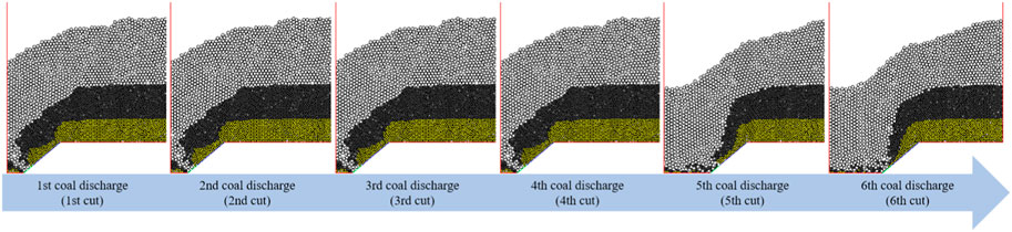
FIGURE 9. Roof coal release process of ‘one mining, one caving’.
In Figure 10, for the ‘two mining, one cave’ mining scheme, the horizontal projection size of the cave opening is lower than that of the cave coal layout, and the speed of coal gangue motion is relatively gentle. The coal recovery rate is relatively high when the goaf and roof gangue at the upper end of the cave opening reach the cave opening at the same time.
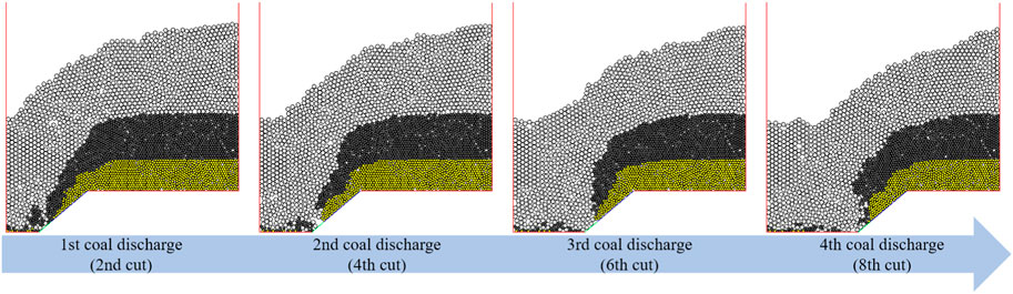
FIGURE 10. Roof coal release process of ‘two mining, one cave’.
Figure 11 shows the ‘three mining, one cave’ mining scheme. For this scheme, the horizontal projection size of the caving opening is lower than that of the caving layout, the total amount of coal released each time in the caving opening is generally larger, the initial boundary of the caving is more inclined to goaf, and the overall span range is wide. The gangues are located at the back under the coal seam, which makes the coal flow at this position inconvenient and slow. If the roof coal below is very close to the cave opening, then under the thrust of the self-weight and the forward motion of the rear gangue, the roof coal will continue to move closer to the cave opening until the cave opening. Since the rear gangue replaced the original roof coal during the migration process, a triangular inaccessible area will be created. Compared with the coal seam located at the upper end of the caving opening, the middle coal seam has a faster coal flow speed and a wider flow space and reaches the opening first. For the roof coal seam area that flows in advance, the total outflow is less, and the upper gangue in the middle area will be concave downward, presenting a concave surface. When the roof coal continues to flow out, the roof coal in the middle position will be replaced by the upper gangue until it flows to the cave opening. This movement will cause the coal body on both sides to fail to release normally, and the central gangue hinders caving. In this case, the work can only be suspended to avoid higher gangue content.

FIGURE 11. Roof coal release process of ‘three mining, one caving’.
When using different caving intervals to mine solid coal or change the caving interval, the total displacement distance of roof coal was 12 (times) × 0.60 = 7.20 m. One unit can be selected for thickness. Within this area, the roof coal and gangues were 30.2 t and 36.0 t, respectively. The figure below shows the caving performance of the three schemes (Figure 12).
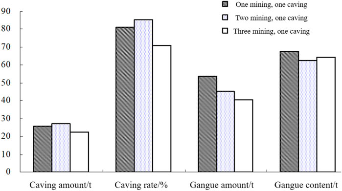
FIGURE 12. Caving performances under three caving intervals.
When using the first scheme for mining, the caving interval was set to 0.60 m, and the horizontal projection length of the caving opening was greater than the caving interval, so the goaf gangue reached the caving opening first. At the beginning of caving, there was a gangue in the caving opening. In this case, continue to discharge coal until a large amount of gangue at the rear moves to the coal discharge port and blocks it, then stop the coal discharge work immediately, to minimize the loss of roof coal and make the total caving capacity 25.72 t, the caving rate of roof coal 85.05%, and a relatively high gangue content of 67.63%. If the caving capacity was increased, the gangue content would also increase, resulting in a lower coal quality. If the coal quality was improved, the total caving capacity would decrease.
When using the second scheme for mining, the caving interval was set to 1.2 m, the horizontal projection size of the caving opening was lower than the caving interval, the total caving capacity reached 27.1 t, the caving rate of roof coal was 89.75%, and the gangue content was 62.50%. Compared with the first scheme, the caving rate of roof coal and coal quality were improved. In this way, the roof coal gangue content and the caving rate can be optimized.
When using the third scheme for mining, the caving interval in this case reached 1.8 m, and the horizontal projection size of the caving opening was also lower than the caving interval. The resulting total caving capacity was 22.6 t, and the caving rate of roof coal was 74.60%. In the ‘three mining, one caving’ scheme, caving funnels were likely to be formed at the upper end of the caving opening, many roof gangues were located at these openings simultaneously, and the particle size of these gangues was large, making them prone to a clogging effect. The caving opening had to be closed in time. In this case, the amount of gangue obtained was the lowest, about 40.7 t. However, the caving capacity was too small, which still caused the gangue content to exceed the second solution, reaching 64.3%. Compared with the second scheme, the caving rate of roof coal decreased significantly, and the mass also decreased accordingly. If coal production needs to be consistent with the second scheme, then the gangue content will increase significantly. If the coal quality needs to be consistent with the second scheme, then the output will decrease significantly.
During caving, it is necessary to comprehensively compare the roof coal gangue content and caving rate and select a suitable caving interval to achieve the highest comprehensive income. We analyzed the caving performance of three kinds of caving intervals to discover that the method of ‘two mining, one caving’ is the most reasonable.
4.3 Simulation of combined fully mechanized caving in terms of caving mode
The figure below shows 10 consecutive supports with a caving opening size of 1.5 m. We simulated the low-level caving and configured the corresponding container at the lower end of the caving opening. Subsequently, we performed a statistical analysis on the gangue and coal volume given in the caving link and obtained the corresponding effects of different caving intervals. Finally, we simulated the following five schemes separately and then compared and analyzed the corresponding caving performance of different caving modes (Figure 13).
(1) Single-cycle interval caving: First of all, we considered the caving opening of the odd-numbered supports from #9, #7, etc., and added the coal. It was found that the gangue is closed to the caving opening, leaving certain gangues and lagging behind them for a certain distance. Subsequently, we put down all the even-numbered supports from #10 and #8 and released the remaining gangue at the same time.
(2) Single-cycle sequential caving: The order of caving follows the order of #1 to #10 cave openings. We carried out sequential caving, and if gangue was found when the support released coal, the caving opening would be closed.
(3) Multi-cycle interval caving: We first considered the support caving openings of #1, #3, etc., released the gangues, and closed the caving openings after coal was found. Subsequently, we opened #2, #4, and other even-numbered supports to release the gangues, and closed the cave openings after coal appeared. Then, we considered the caving openings of the odd-numbered supports and released the roof coal. After seeing the gangues, we closed the caving openings, reopened the even-numbered supports again to release coal, and closed it after discovering the gangues.
(4) Multi-cycle sequential caving: We released the gangues in the order of #1 to #10 and closed the caving opening after coal was found. Subsequently, we opened these one by one to release the roof coal and closed the cave opening after the gangue appeared.
(5) Single-cycle alternative caving: Similar to single-cycle interval caving, we first opened the caving openings of #1, #3, and other odd-numbered supports, and released coal. After seeing the gangue, we closed the caving openings, leaving residual gangue. For the closed even-numbered supports, when the workface completed a cycle, we opened #2, #4, #6, #8, and other double number supports. Close the single number.
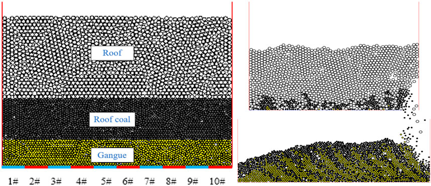
FIGURE 13. Initial model for fully mechanized caving.
As shown in Figure 14, when the single-numbered support finishes coaling, the falling space generated at the upper end of the support resembles an ellipsoid. As two adjacent odd-numbered caving openings are spaced apart from double-numbered caving openings, there is a certain distance between these two odd-numbered cave openings, which makes it difficult for the two coal-release ellipsoids to be tangential. Hence, we left the gangue at the top of the double-numbered caving opening. It can be seen from the analysis diagram that the gangues are in the form of straight walls and semi-circular arches. When the even-numbered supports released coal, gangue could be released via the caving opening, because the falling space exceeded the shape of the roof coal itself, a part of the roof coal slipped from the cave opening, and was then released. However, a part of the roof coal was included in the caving opening of the adjacent odd number, which was difficult to be released, thus causing the loss of roof coal.
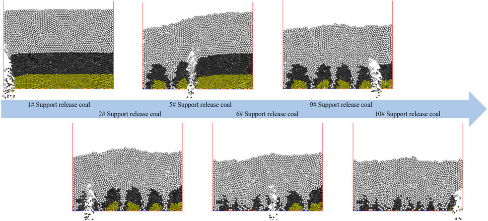
FIGURE 14. Workface 822 single-cycle interval caving process.
Figure 15 illustrates the process of single-cycle sequential caving. When the first caving opening completed the coal release, the roof gangue at the upper end filled the space left by the roof coal; after closing the first cave opening and opening the second cave opening, a cave arch was formed above the support, one side of the arch was the cave gangue, and the other side was the gangue and roof coal. The arch height of the caving arch continued to develop, and when the arch height reached the roof, the gangue above the caving opening descended to the caving opening, and coal release was completed. In cases such as this, the roof coal is prone to unbalanced forces, which means that, after the coal release of the previous support is completed, the roof coal above the adjacent support will move towards it, and the roof coal will have a horizontal displacement within the plane parallel to the wall. Moreover, part of the roof coal will slide to the previous caving opening and it is difficult to be released due to the effect of inertia, which will cause losses.

FIGURE 15. Single-cycle caving in Workface 822.
Figure 16 shows the process of multi-cycle interval caving. There was a triangular gap at the top of the single number support. In this case, the pressure of the overlying coal rock was more concentrated on the upper end of the double-number support, and the coal at the upper end was more affected by the gravity. For this reason, the gangue had a faster release speed after the even-number support caving opening was turned on. After the gangues were placed on the even-numbered supports, the coal seam above the odd-numbered support was compacted due to the subsidence of the upper coal and the migration of the coal seam above the adjacent support. Every time the coal was released, the contact surface of the coal rock moved, and when the near-roof coal was released, the gangue had already mixed in. The interface of the coal rock corresponding to this method showed a steady decline, which can reduce the occurrence of gangue. Roof coal can be destroyed after arching and has a high caving rate. However, the operation was quite cumbersome, the quantity of mixing and the mixed gangue layer were increased, and the release of coal slowed down.
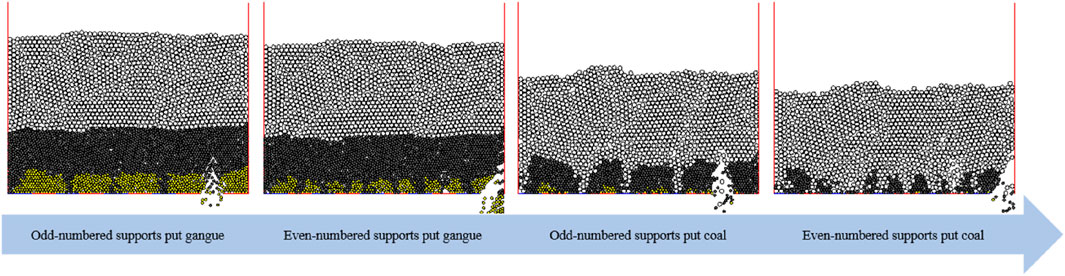
FIGURE 16. Multi-cycle interval caving in Workface 822.
Figure 17 shows the process of multi-cycle sequential caving. After opening the fourth cave opening and adding the gangues, a cave arch was formed on the top of the cave opening, and the arch height continued to increase. When the arch reached the coal seam, the coal above the cave opening collapsed, and in this case, we closed the cave opening at the end of the gangue release. After the first round of the sequential release of gangues, there were gangue residues on either side of each caving opening, which were difficult to release. Hence, the interface between the roof and roof coal showed a uniform decline when the gangue was released. At the end of the opening of the fourth cave, a cave arch was formed above the cave opening, and when the arch height reached the roof gangue, the gangue above the caving opening collapsed at the opening. In this case, we closed the caving opening, and the caving ended. Finally, part of the roof coal on both sides of the caving opening could not be released, resulting in the loss of coal.
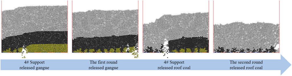
FIGURE 17. Multi-cycle sequential caving in Workface 822.
Figure 18 shows the single-cycle alternate caving mode, which is like the single-cycle interval caving. Firstly, the cave opening on the upper end of the odd-numbered support carried out the caving, and when gangue was encountered, we closed the cave opening, resulting in the corresponding gangues being left in the even-numbered support. Although this mode made some gangues into goaf, with lower gangue content, however, there was more roof coal at the goaf at the upper end of the gangues, resulting in a decrease in the caving rate of roof coal.
FIGURE 18. Multi-cycle interval caving in Workface 822.
When using different caving modes or changing the caving mode when mining solid coal, the total displacement distance of the roof coal was 10 × 1.5 = 15 m. Thickness was taken as 1 unit, and the range contained 63 t roof coal and 75 t gangues, and the performance of the five caving modes is shown in Figure 19. It can be seen that the coal discharge effect of the single interval, multi-round sequence, and multi-round interval methods are relatively close, and the effect of multi-round sequence is the best, but in the actual operation process, the labor and time consumption is greater. Therefore, choosing a single-discussion interval method can not only guarantee the effect, but also save costs.
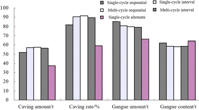
FIGURE 19. Performance of the five caving modes of Workface 822.
5 Conclusion
According to the geological and mining technical conditions of the 822 working face of the Yuandian No. 1 Coal Mine, the project used laboratory tests, numerical simulation tests, theoretical analysis, and other methods to conduct research. The coal discharge effect of different coal discharge processes was evaluated with the indicators of coal discharge rate, top coal discharge rate, gangue release amount, and gangue content rate, and the reasonable top coal caving process parameters were determined. The following conclusions were obtained.
1) Under the action of mining-induced stress, the peak pressure on the support is less than the rupture stress of gangues. Relying on the support pressure of the mine can make the roof coal rupture, but it is difficult to rupture the gangue in the roof coal. Owing to the gangue-containing coal seams, the damage coefficient of the roof coal at the upper end of the support is lower than 1. The original support on the front end is further extended to the upper area of the entire support, and the roof coal crushing effect is greatly weakened.
2) The caving performance corresponding to three caving arrangements were analyzed. If the thickness of the gangue-containing coal seam in the workface and roof coal reaches 5 m, using the ‘two mining, one caving’ scheme can optimize the roof coal gangue content and caving rate. After comparing and analyzing the caving performance of five caving modes such as the single-cycle sequence and interval, we concluded that, in the caving process, not only should the amount of released gangue be reduced, but also the caving capacity should be increased, and the single-cycle interval caving mode should be clearly used.
3) Considering the particular case of Workface 822 of the Yuandian No. 1 Mine, according to the results of the numerical simulation, we concluded that all caving processes need to release the gangue at the lower end of the roof coal, prior to the extraction of the coal itself. If the gangues and roof coal are 2 m and 3 m deep, respectively, the minimum gangue content is approximately 54.4%.
Data availability statement
The original contributions presented in the study are included in the article/Supplementary material, further inquiries can be directed to the corresponding author.
Author contributions
Conceptualization, XH and XC; methodology, ZL and YD; software, YD, XH, and XC; validation, ZL and YD; writing–original draft preparation, XC; writing–review and editing, XC and ZL; project administration, YD. All authors contributed to the article and approved the submitted version.
Funding
This work was supported by the Natural Science Research Project of Anhui Educational Committee (KJ2021A0456), the Collaborative Innovation Project of Anhui Universities (GXXT-2019-029), and the National Natural Science Foundation of China (52130402).
Conflict of interest
Authors XH, PL, and YD were employed by the Ningxia Hongdunzi Coal Industry Co., Ltd.
The remaining authors declare that the research was conducted in the absence of any commercial or financial relationships that could be construed as a potential conflict of interest.
Publisher’s note
All claims expressed in this article are solely those of the authors and do not necessarily represent those of their affiliated organizations, or those of the publisher, the editors and the reviewers. Any product that may be evaluated in this article, or claim that may be made by its manufacturer, is not guaranteed or endorsed by the publisher.
References
Bu, Q., Tu, M., and Fu, B. (2021). Research on the redistribution law of lateral mining stress and the bearing characteristics of section coal pillar in extra-thick fully mechanized top-coal caving mining. Shock Vib. 2021, 1–17. doi:10.1155/2021/4355977
Chen, D., Zhu, J., Ye, Q., Ma, X., Xie, S., Guo, W., et al. (2023). Application of gob-side entry driving in fully mechanized caving mining: A review of theory and technology. Energies 16, 2691. doi:10.3390/en16062691
Chen, Y., Wang, Z., Hui, Q., Zhu, Z., Sun, D., Chen, Y., et al. (2022). Overlying rock movement and mining pressure in a fully mechanized caving face with a large dip angle. Front. Earth Sci. 10. doi:10.3389/feart.2022.963973
Cui, F., Dong, S., Lai, X., Chen, J., Cao, J., and Shan, P. (2019). Study on rule of overburden failure and rock burst hazard under repeated mining in fully mechanized top-coal caving face with hard roof. Energies 12, 4780. doi:10.3390/en12244780
Dai, J., Shan, P., and Zhou, Q. (2020). Study on intelligent identification method of coal pillar stability in fully mechanized caving face of thick coal seam. Energies 13, 305. doi:10.3390/en13020305
Du, H., and Song, D. (2022). Investigation of failure prediction of open-pit coal mine landslides containing complex geological structures using the inverse velocity method. Nat. Hazards 111, 2819–2854. doi:10.1007/s11069-021-05159-w
Du, H., Song, D., Liu, G., Guo, W., Wang, X., and Bai, R. (2023). Influence of the extra-thick coal seam exploitation on the deformation characteristics of the overlying rock mass in an open-pit mine slope. Geomatics Nat. Hazards Risk 14, 1–23. doi:10.1080/19475705.2022.2161952
Fu, C., Lu, F., and Zhang, G. (2023). Gradient- enhanced waterpixels clustering for coal gangue image segmentation. Int. J. Coal Prep. Util. 43, 677–690. doi:10.1080/19392699.2022.2074409
Hao, J., Chen, A., Li, X., Bian, H., Zhou, G., Wu, Z., et al. (2022). Analysis of surrounding rock control technology and its application on a dynamic pressure Roadway in a thick coal seam. Energies 15, 9040. doi:10.3390/en15239040
He, Y., and Huang, Q. (2023). Simulation study on spatial form of the suspended roof structure of working face in shallow coal seam. Sustainability 15, 921. doi:10.3390/su15020921
Jiang, B., Gu, S., Li, W., Zhang, G., and Zhang, J. (2021). Case studies of comprehensive gas control method during fully mechanized caving of low-permeability ultrathick coal seams. Geofluids 2021, 1. doi:10.1155/2021/5558678
Jiang, B., Xin, Z., Zhang, X., Deng, Y., Wang, M., Li, S., et al. (2023). Mechanical properties and influence mechanism of confined concrete arches in high-stress tunnels. Int. J. Min. Sci. Technol., 2023. doi:10.1016/j.ijmst.2023.03.008
Liang, Y., Ran, Q., Zou, Q., Zhang, B., and Hong, Y. (2022). Experimental study of mechanical behaviors and failure characteristics of coal under true triaxial cyclic loading and unloading and stress rotation. Nat. Resour. Res. 31, 971–991. doi:10.1007/s11053-022-10022-1
Liu, C., Mitri, H., and Li, H. (2022). Coal and gangue active identification method using microwave irradiation-infrared detection. Minerals 12, 951. doi:10.3390/min12080951
Lyu, X., Chi, X., Yang, K., Yuan, L., Fang, J., and Zhang, Z. (2023a). Strength modeling and experimental study of coal pillar-artificial dam combination after wetting cycles. J. Mater. Res. Technol. 25, 3050–3060. doi:10.1016/j.jmrt.2023.06.139
Lyu, X., Yang, K., Fang, J. J., Tang, J. Z., and Wang, Y. (2023b). Feasibility study of construction of pumped storage power station using abandoned mines: A case study of the shitai mine. Energies 16, 314. doi:10.3390/en16010314
Lyu, X., Yang, K., and Fang, J. J. (2022). Utilization of resources in abandoned coal mines for carbon neutrality. Sci. Total Environ. 822, 153646. doi:10.1016/j.scitotenv.2022.153646
Lyu, X., Zhang, T., Yuan, L., and Fang, J. (2023c). Prospects for the transformation and development of carbon storage in abandoned mines of coal enterprises from the perspective of carbon neutrality. Int. J. Coal Sci. Technol. 10, 36. doi:10.1007/s40789-023-00593-6
Nan, H., and Wang, S. (2022). Migration law of different top coal thicknesses in top coal caving. Front. Earth Sci. 10. doi:10.3389/feart.2022.999979
Shi, J., Yan, S., Xu, Z., Xue, J., Kaikai, Z., and Zheng, J. (2021). Analysis of the progressively enhanced mine pressure in the fully mechanized top coal caving work face of a 20 M ultra-thick coal seam. Shock Vib., 2021, 1, 11. doi:10.1155/2021/6678207
Si, L., Xing, F., Wang, Z., and Tan, C. (2022). Electromagnetic wave forward modeling of coal-gangue mixed model in top coal caving mining face. Simulation-transactions Soc. Model. Simul. Int. 98, 1127–1142. doi:10.1177/00375497221105290
Song, D., and Du, H. (2023). Numerical investigation of the evolution process of an open-pit mine landslide using discrete-element method. Int. J. Geomechanics 23. doi:10.1061/IJGNAI.GMENG-7568
Tang, S., and Tang, C. (2012). Numerical studies on tunnel floor heave in swelling ground under humid conditions. Int. J. Rock Mech. Min. Sci. 55, 139–150. doi:10.1016/j.ijrmms.2012.07.007
Tu, M., Bu, Q., Fu, B., and Wang, Y. (2020). Mechanical analysis of mining stress transfer on isolated island face in extra-thick fully mechanized top-coal caving mining. Geofluids 2020, 1. doi:10.1155/2020/8834321
Xie, S., Wu, X., Chen, D., Sun, Y., Wang, E., Wu, X., et al. (2020). Failure mechanism and control technology of thick and soft coal fully mechanized caving Roadway under double gobs in close coal seams. Shock Vib., 2020, 1. 23. doi:10.1155/2020/8846014
Xie, S., Wu, Y., Ma, X., Chen, D., Guo, F., Jiang, Z., et al. (2022). Reasonable stopping method and retracement channel support at fully mechanized top coal caving working face of 15 M extra-thick coal seam: A case study. Energy Sci. Eng. 10, 4336–4357. doi:10.1002/ese3.1301
Yang, L., Wang, J., Yang, S., Li, T., Wei, W., Li, Z., et al. (2023). Influence of loose gangue thickness on top coal recovery ratio in extrathick coal seam in longwall top coal caving. Comput. Part. Mech. 2023, 1. doi:10.1007/s40571-023-00567-0
Yang, Y., Zhang, Y., Zeng, Q., Wan, L., and Zhang, Q. (2022). Simulation research on impact contact behavior between coal gangue particle and the hydraulic support: Contact response differences induced by the difference in impacted location and impact material. Materials 15, 3890. doi:10.3390/ma15113890
Yang, Z., Cheng, Z., Li, Z., Li, C., Wang, L., Yin, S., et al. (2021). Movement laws of overlying strata above a fully mechanized coal mining face backfilled with gangue: A case study in jiulishan coal mine in henan province, China. Adv. Civ. Eng., 2021, 1, 20. doi:10.1155/2021/9939886
Yin, Q., Wu, J., Zhu, C., He, M., Meng, Q., and Jing, H. (2021). Shear mechanical responses of sandstone exposed to high temperature under constant normal stiffness boundary conditions. Geomechanics Geophys. Geo-Energy Geo-Resources 7, 35. doi:10.1007/s40948-021-00234-9
Zhang, G., Li, Q., Xu, Z., and Zhang, Y. (2022a). Roof fractures of near-vertical and extremely thick coal seams in horizontally grouped top-coal drawing method based on the theory of a thin plate. Sustainability 14, 10285. doi:10.3390/su141610285
Zhang, J., Han, X., and Cheng, D. (2022b)., 189. Measurement. doi:10.1016/j.measurement.2021.110445Improving coal/gangue recognition efficiency based on liquid intervention with infrared imager at low emissivityMeas. (. Mahwah. N. J).110445
Zhao, T., Xu, G., Zhou, Y., Huang, Z., Xue, J., and Du, L. (2022). CDEM simulation of top-coal caving characteristics under synchronous multiwindow drawing in longwall top-coal caving mining of extra-thick coal seam. Engineering 10, 3617–3637. doi:10.1002/ese3.1245
Keywords: mining engineering, gangue-containing coal seams, combined fully mechanized caving, numerical simulation, parameter optimization
Citation: Hao X, Liu P, Deng Y, Chi X and Li Z (2023) Near crushing mechanism of gangue-containing coal seams and parameter optimization for combined fully mechanized caving. Front. Earth Sci. 11:1233485. doi: 10.3389/feart.2023.1233485
Received: 02 June 2023; Accepted: 20 July 2023;
Published: 04 August 2023.
Edited by:
Feng Du, China University of Mining and Technology, ChinaReviewed by:
Danqing Song, South China University of Technology, ChinaChun Zhu, Hohai University, China
Copyright © 2023 Hao, Liu, Deng, Chi and Li. This is an open-access article distributed under the terms of the Creative Commons Attribution License (CC BY). The use, distribution or reproduction in other forums is permitted, provided the original author(s) and the copyright owner(s) are credited and that the original publication in this journal is cited, in accordance with accepted academic practice. No use, distribution or reproduction is permitted which does not comply with these terms.
*Correspondence: Xiaobo Hao, aHhiaWFvMjAyMEAxNjMuY29t