 Chenghua Li
 Zhiping Li1
94% of researchers rate our articles as excellent or good
Learn more about the work of our research integrity team to safeguard the quality of each article we publish.
Find out more
ORIGINAL RESEARCH article
Front. Earth Sci., 12 July 2023
Sec. Environmental Informatics and Remote Sensing
Volume 11 - 2023 | https://doi.org/10.3389/feart.2023.1209743
This article is part of the Research TopicUnderstanding of Big Data and Artificial Intelligence in Promoting the Environmental GovernanceView all 6 articles
Gas-liquid separator is an important surface equipment in oilfield development. Improving the separation efficiency of separator is of great significance to the overall economic benefit of oilfield. Spiral separator is a high efficiency separation device that has been widely used, but at present, there are not enough studies on separation efficiency in number of spiral turns and pitches. In view of this problem, this paper analyzed the gas–liquid separation efficiency of spiral separators with different number of spiral turns and pitches via the fluent numerical simulation software and laboratory experiments. The results showed that a greater number of spiral turns and a larger particle diameter could lead to higher separation efficiency. The separation efficiency has an optimum value for the pitch. The performance of the downhole spiral separator was verified by laboratory experiments, and the separation efficiency was above 90% under the conditions where the treatment amount was either unchanged or changed. These results can provide a reference for the application of spiral separators in oil fields.
As global industrialization continues to accelerate, energy consumption has surged. At present, the energy system composed of fossil energy such as oil, coal and natural gas will remain mainstream for a long time. As a representative of clean energy, natural gas has the advantages of large reserves, high calorific value, convenient transportation, safety and efficiency, and is gradually replacing the status of traditional industrial energy such as coal and oil (Hafezi et al., 2021). Natural gas is a fuel with relatively low carbon emissions (Makogon, 2010) and its huge energy potential has attracted widespread attention from countries around the world (Zhu et al., 2021). With the increased productivity of oil fields, the water content of natural gas production has continued to increase annually (Harris et al., 1999). But a small amount of liquid in the wellbore can increase the backpressure of the gas well production layer. The discontinuation or reduction of gas wells production caused by downhole effusion significantly affects the productivity of gas fields, which can lead to a reduction of both the gas recovery period and the ultimate recovery of gas reservoirs. Therefore, the increase of water production in gas wells poses a critical threat to natural gas production. Thus, gas–water separation and its treatment are gaining significance (Qu et al., 2006; Qiu and Wang, 2020).
Gas-liquid separation technology is important to ensure the safe and efficient operation of industrial equipment so it plays a significant role in many fields (Liu et al., 2020). Gas-liquid separation devices can be divided into two categories: one is gravity settlement (Fitnawan et al., 2009; Lopez et al., 2019), the density difference between the gas phase and the liquid phase is used to achieve the gravity separation. But gravity settlement requires a large settlement space and a long settlement time, so it is not suitable for spaces with limited underground structures; the other is to use the different centrifugal forces generated by rotation to achieve phase separation. The fluid flows into the cyclone from the tangential inlet and rotates in the form of vortices inside the separator. The two phases are separated due to the difference in density. Cyclone separator (Zhou et al., 2018; Wei et al., 2020) and spiral separator (Wang et al., 2018; Najafi et al., 2020) are widely used.
The cyclone separator is cheaper and has better adaptability in harsh environment (Lim et al., 2004). It has good performance in low gas-liquid ratio well. The principle is that a large centrifugal force will be generated when the fluid passes through the cyclone due to the density difference between the phases in the mixture and the action of centrifugal force, less dense phase will gather in the central area, and that the denser phase will move outward, thereby achieving separation (Xiaoming et al., 2020). But according to Wasilewski, the cyclone separators are low efficiency separators (Wasilewski, 2017). The spiral gas–liquid separator is a simple, novel, efficient, and compact gas–liquid separator which can be used for gas–liquid separation for in ground or underground gas extraction, oil and gas separation in oil extraction (Weingarten et al., 1997; Bo et al., 2003), helium separation in the aerospace, and for application as a water treatment device (Mondt, 1996). The general working principle of the spiral separator is as follows: fluid medium enters tangentially from the side of the device and flows from top to bottom, and the fixed spiral blade in the separator rotates the fluid. Due to the density difference, low density fluid moves towards the inner wall of the separator and denser fluid moves toward the outer wall. The effect of gravity causes the denser fluid to flow downwards and the less dense fluid to flow upwards (Qiu and Wang, 2020). The performance of the separator depends on the pitch, diameter, length of the screw and the liquid and air flow.
Currently, spiral separators are more applied in gas-liquid separator of downhole natural gas. Many scholars have carried out experimental research to discuss the factors affecting the optimal design and separation efficiency of internal components. Zhou investigated the influence of pitch and spiral number in the separation efficiency (Zhou et al., 2004) and found that with the increase of pitch and number of spiral turns, separation efficiency increased first and then decreased. And he also verified an equation for the pressure drop of the separator based on the Darcy program whose error was within 20%. Wang et al. (2021) found that the liquid film overflow of the cylinder on the gas-liquid cylindrical cyclone was the primary factor leading to the inefficiency of the cyclone, and the generation of liquid film was directly related to the flow trajectory of the liquid phase in the inlet pipe and the short circuit flow at the intake nozzle. Nagdewe et al. (2008) found that the outlet pipe was doped with liquid particles, which made the separation efficiency of the gas-liquid separator not reach the optimal value, and they further improved the performance of the traditional centrifugal separator by changing the effective length of the separation space. In 1992, Markov et al. investigated the factors that affect fluid flow in a spiral separator through experimental analysis. Some empirical approximation formulas were presented in their study in addition to examples of quantitative calculations of pressure loss (de Hoxar, 2000). Rui et al. (2021) discussed the variation trend of gas phase medium distribution, rate field and pressure loss under the presence or absence of ejector needles at the bottom of the gas-liquid cyclone and its different ejector shapes. Millington and Thew (1987) accurately measured the flow field rate distribution of the columnar separator according to the experiment, and the results showed that the spacing between the separator inlet and the overflow section was the main reason for determining the strength of liquid gas carrying phenomenon. Anderson et al. (2021) took the axial cyclone as the research object to investigate the influence of gas-liquid flow velocity, inlet tube shape and relative injection angle to the gas-liquid separation performance, and they established an empirical correlation function to predict the vortex pitch, which could guide the design of efficient gas-liquid separator. Lan et al. (2022) designed a downhole spiral gas-liquid separator suitable for high gas-liquid ratio (liquid content less than 10%), and analyzed the velocity field and pressure field distribution in the separator by using the RNG k-e turbulence model. Gomez et al. (2000) created a universal discrete variable phase trajectory solid model based on the different flow patterns generated at the separator inlet to analyze the motion trajectory of liquid droplets in gas and bubbles in liquid. Rosa invented the spiral vane gas-liquid separator for wellhead oil-gas separation. The spiral structure was used to generate centrifugal force to separate gas and liquid, which solved the blockage and segmented plugging flow phenomenon in the process of oil and gas gathering and transportation (Rosa et al., 2001). Zhou et al. (2020) proposed a new gas-liquid vortex separator (GLVS), which symmetrically arranged multiple swirl arms within the separator. Dries and Hoffmann, (2019) found that the vane mist eliminator was a high-efficiency droplet separator because it was durable and had certain stain resistance, and the separation efficiency was still high at higher working pressures. Cui, (2010) developed and designed the spiral blade drainage gas-liquid separator, which was suitable for the slender space in the wellbore and could be directly separated under the formation. And it could reduce the pressure drop caused by the loss of energy during the transportation of the gas-liquid mixed phase. Zhang introduced the field application of spiral gas-liquid separator (Zhang, 2001). He pointed out that installing a spiral gas-liquid separator on the pipeline could improve the processing capacity of the subsequent oil-water separator. But at present, there are not enough studies on separation efficiency in number of spiral turns and pitches, which are important parameters to the separation efficiency of the spiral separator. Owing to the complexity of fluid movement in the gas–liquid two-phase flow field, the actual flow field conditions cannot be accurately described. As such, numerical simulations have become an important tool for investigating this problem. In the simulation research process, there are three main theoretical models of gas-liquid two-phase flow: continuum model (Hongyu, 2015), volume of fluid model (Le et al., 2018) and discrete particle model (Safikhani and Mehrabian, 2016; Chen et al., 2020; Zeng et al., 2021). Scholars used turbulence simulation calculation models to test the flow pattern, bubble shape, separation performance and pressure drop in the separator (Liu et al., 2019; Qiu et al., 2020; El-Emam et al., 2021; Meng et al., 2021; Xu et al., 2021).
With the development of numerical simulation technology, the study of numerical simulation of spiral separator has become a powerful tool for optimal design of spiral separator. Cui (2010) carried out numerical simulation of the spiral blade gas-liquid separator, and analyzed the influence of different structural parameters and operating parameters on the separation performance of spiral blade. Qu et al. (2011) conducted a sensitivity analysis of the parameters affecting the separation effect of the spiral vane downhole oil and gas separator and found that increasing the inner radius of the spiral and the total length of the spiral could improve the separation effect, while increasing the pitch length of the spiral and outer radius would reduce the separation efficiency. Fu used Fluent to numerical simulation to investigate the downhole spiral gas-liquid separator (Fu, 2009). Liang et al., (2015) proposed a special separation device to study the separation process of gas-liquid two-phase flow. They had observed laminar flow, circulation flow and segment plug flow, and the experimental results showed that the two-phase separation was affected by the location distribution area of the fracture gap and the relative velocity of gas and liquid. Wang et al. (2017) simulated the flow of droplet particles in the annular circulation system area of the gas-liquid separator, and simulated the droplet motion trajectory from three levels: droplet impact, droplet cracking and droplet collision with boundary layer. Considering the sudden deformation of droplets during rotation and they analyzed the relative changes of gas phase and liquid phase flow field. Chang and Dhir (1994) used simulation software to study the gas-phase cyclone field in tangential inlet cyclone tubes, and confirmed that the tangential and axial velocity distributions in cyclones were closely related to the turbulence intensity of different sections. Oh et al., (2014) analyzed the potential influence of structural features such as the number of guide vanes, the length of the main diameter and the exhaust pipe on the axial flow gas-liquid separator according to the finite element simulation software, and improved the main characteristic parameters according to the test results. Kou et al. [50] introduce free energies to account for the liquid–gas capillarity effect and gas compressibility, and then using the second law of thermodynamics, rigorously derive a thermodynamically consistent model for immiscible gas–liquid two-phase flow in porous media, it brings guidance significance for the follow-up oil production work [51,52].
In this paper, we focus on the significant parameters which are number of spiral turns and pitches to study their effect on separation efficiency. In the second part, we use Fluent as numerical simulation means to research the efficiency of spiral separator with different number of spiral turns and pitches. And in the third part, based on the numerical simulation analysis, we design a separator with a pitch of 23 mm whose separation efficiency is over 90%. At last, this paper proposes further research direction which is the test of gas-liquid separation in high pressure condition.
In order to access numerical simulation, the first step is to establish suitable geometric model. Figure 1 shows the spiral structure and partial enlargement of the actual separator. Figure 2 shows the computational geometry model and a partial enlargement created in GAMBIT2.4, a pre-processing software for the computational fluid dynamics software FLUENT6.0. For the convenience of reducing the complexity of the calculations, the model was simplified, and the boundary condition of the escape wall surface was used to replace the gap between casing and spiral. Table 1 gives the size of the geometric model.
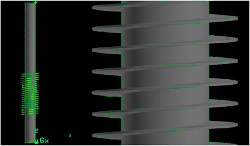
FIGURE 1. Spiral structure and partial enlargement.
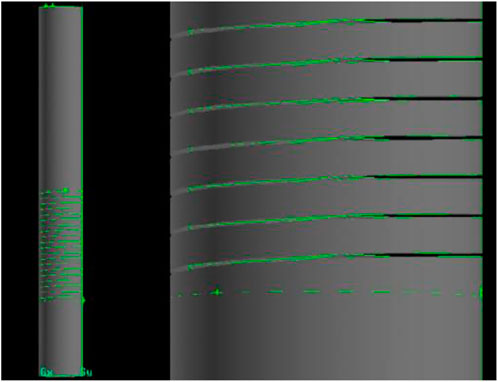
FIGURE 2. Computational geometry model and a partial enlargement of the actual separator.
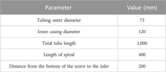
TABLE 1. The size of the geometric model.
After the establishment of geometric model, it is necessary to establish the corresponding physical model by dividing the appropriate mesh and defining boundary conditions of the geometric model for the subsequent numerical solution. We use the same flow pattern determination method as R. Manabe (Zhang, 2001).
The turbulent flow of fluid in spiral structure has curvature and great tangential velocity, which plays an important role in the whole flow characteristics and belongs to the range of strong swirling flow.
In order to reflect the anisotropy of Reynolds stress in strong swirling flow field, the Reynolds stress model (RSM), a high-order turbulence model equation and an improvement model of the
The equation describing the gas phase motion in a helical vane guided gas-liquid separator can be derived from the law of conservation of mass (continuity equation), conservation of momentum and conservation of energy.
Continuity equation:
Momentum equation:
The model closes the fundamental equation by solving the Reynolds stress transport equation as follows:
After the simulation closure of the equation, the specific forms of the terms on the right end are as follows:
Turbulent diffusion term:
Stress-generating term:
Pressure strain term:
Viscous dissipation term:
Turbulent energy produces terms:
Where,
Therefore, the basic closed equations of the RSM model are constructed. The model constants are selected according to experience, as shown in Table 2.
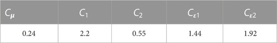
TABLE 2. RSM model related constant.
In order to facilitate the calculation and save the time and space of calculation, it is also necessary to make certain assumptions and simplified handlings to the calculation fluid:
We assumed that:
① The movement of the fluid can be seen as continuous.
② The fluid is homogeneous.
③ When the fluid is at rest, the total pressure is hydrostatic.
④ If the inlet is infinite and uniform flow, the inlet velocity end face is evenly distributed.
⑤ The speed that controls the fluid in the body is independent of time, so the fluid is a steady-state flow.
Mesh division is based on the spiral structure of the spiral separator, for mesh division, sensitivity analysis was carried out to ensure the shortest running time under the premise of high separation efficiency. The spiral structure is formed by rotating a rectangular plane with one side perpendicular to the rotary axis and one side intersecting the rotary axis around the rotary axis in a certain rotation direction. Due to the complexity of the spiral structure, it is divided by an unstructured tetrahedral grid. The grid distribution of the calculated geometry model is shown in Figure 3, and the encryption grid is adopted in the complicated region of the flow field. The number of divided elements is about 1 million.
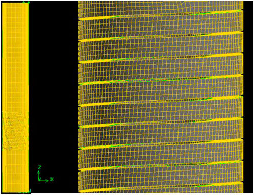
FIGURE 3. Spiral structure mesh.
The physical model should include information about boundary conditions and fluid space. However, due to the limitations of the calculation condition, only the information on the boundary is currently considered in the engineering calculation. When using the physical model of the fluid as the calculation object, boundary conditions are defined on all boundaries that constrain the fluid.
(1) Import and export boundary
The operating gas in spiral structure of the downhole gas–liquid separator is the air. The relative parameters are given in Table 3. Spiral channel boundary surfaces are defined as non-slip velocity boundaries, and on the inner wall of the downhole gas–liquid separator, the fluid velocity and related turbulence parameters were taken as zero. The velocity boundary is adopted in the inlet section and the outlet is set to a pressure boundary condition whose pressure is 0 MPa and the temperature is 44°C. The spiral slice of the diversion wall structure using a fixed temperature wall boundary and the temperature is 44°C.
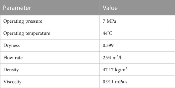
TABLE 3. Import and export boundary parameters.
Since there is no heat exchange problem in the single-phase flow field of the gas in the spiral structure, the thermal boundary conditions are not considered here. The wall surface function was used to simulate the wall boundary layer flow field. When calculating the droplet flow field, the droplets are captured by the wall when they come into contact with it. We assume that the captured droplets can flow downwards under the influence of gravity.
And for liquid particles we assumed that:
① All the liquid particles are discrete groups that slipped with the fluid.
② The initial orbital model did not take into account turbulent diffusion, viscosity and heat conduction of particles.
③ The size of liquid particles is uniform.
④ The particles all start from the velocity inlet and move along their respective orbits.
⑤ The mass, momentum, and energy source of the particles acting on the fluid are equally distributed within the fluid unit for investigation purposes.
(2) Solid wall conditions
The separator is a solid wall with no slip and no mass addition; Exports are treated under fully developed conditions and must meet the overall conservation of quality; The turbulence parameters near the wall are determined by the wall function method.
The turbulence model with high Re number is only suitable for turbulent flow area at a certain distance from the wall, while in the viscous bottom area near the wall, the viscosity phenomenon is dominant, the fluid flow rate is low, and it is in a laminar flow state, so the method of low Re number model simulation or wall function correction can be used. As for modified high Re number model: Although it is still applicable in the viscous bottom layer near the wall, due to the large velocity gradient and temperature gradient in the viscous bottom layer, a considerable number of nodes need to be arranged when doing numerical calculations, so it occupies more computing time and memory. It is an ideal method to use the wall function method combined with the turbulence model to solve the complex flow problem of engineering. The basic idea of this method is that no nodes are arranged in the viscous sublayer, and the first inner node adjacent to the wall is arranged in the area of strong turbulence. The shear stress and heat flux density on the wall are still calculated according to the velocity and temperature difference between the first inner node and the wall. Therefore, the wall function method is used to determine its solid wall boundary conditions. The wall function is easy to implement, and can effectively save memory and calculation time (without arranging too many nodes in the sublayer), which has important practical significance for engineering turbulence calculation, and its accuracy is often comparable to the low Reynolds number method.
It is assumed that the area near the wall of the calculated problem is outside the viscous bottom layer (log-law layer), and the distribution of dimensionless velocity and dimensionless temperature obey the log-law distribution.
Where,
In order to more clearly show the numerical simulation model and boundary conditions used in this paper, a schematic diagram of the model and flow process is given in Figure 4. The blue part in the lower left corner represents the two-phase fluid inlet, the red part in the upper right corner represents the gas outlet, the light blue part represents the wall boundary, and the line represents the flow field track.
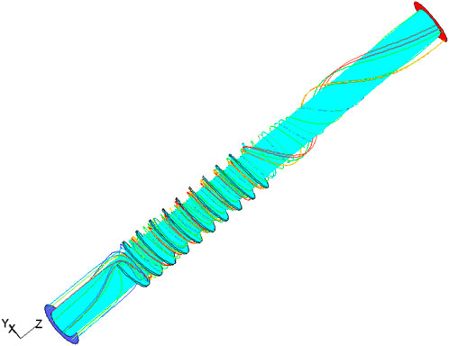
FIGURE 4. The schematic diagram of the model and flow process.
Common parameters of spiral separator are number of spiral turns, pitch, spiral inner diameter, spiral outer diameter. The inner and outer diameters are determined according to the site conditions, and the common sizes are 73 and 115 mm respectively. The uncertainty of the number of spiral turns and pitch is strong and directly affects separation effect of the separator, so this study designs the scheme of different spiral turns and pitch through numerical simulation and experiments, so as to explore a separator with high separation efficiency. We design eight schemes, as shown in Table 4. We selected some widely used parameters for permutation and combination to study the coupling effect between parameters and find the optimal setting.
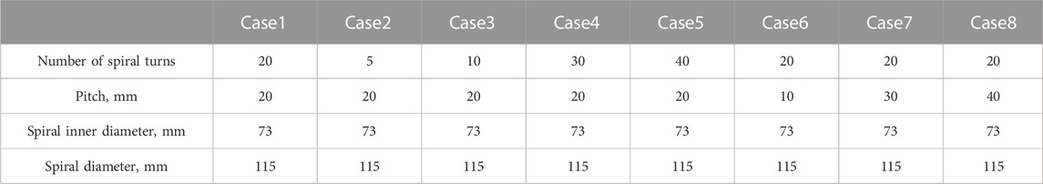
TABLE 4. Geometric model structure parameters of underground gas–liquid separator.
After numerical calculation of the gas continuous phase flow field and liquid particle phase flow field in the underground gas–liquid separator with different pitch and number of spiral turns, we obtain the motion trajectories of representative particles which are in different particle diameters and uniformly distributed throughout the separator. The convergence criterion of the numerical modeling is 1 h running time. We can also obtain the motion trajectory diagram of the liquid particles in the entire downhole gas–liquid separator. The separation efficiency
When droplets of different particle sizes are separated in the spiral structure with different pitches and different number of spiral turns, the separation efficiency is shown in Table 5.

TABLE 5. Droplet efficiency of different spiral structures and particle sizes.
The relation curve between the separation efficiency and spiral number of particles of different particle sizes can be drawn from Table 3 and is shown in Figure 5, the relation curve between separation efficiency and pitch of particles of different particle sizes is shown in Figure 6. Supplementary Figure S2 shows the separation trajectory of particles with different diameters. Based on the analysis of the curves and cloud maps, it can be concluded that:
(1) Under the condition of the same spirals and particle diameter, the separation efficiency of the spiral structure with a pitch of 20 is higher than those of other structures. It is not like that the smaller the pitch, the higher is the separation efficiency. A larger pitch means that the spacing between adjacent helical pieces is larger, allowing particles to have a longer retention time in the helix. This prolongs the interaction time between the particles and the fluid, allowing the particles to be more fully affected by the inertial centrifugal force, thus increasing the separation efficiency.
(2) Under the condition of the same pitch and particle diameter, the more spirals there are, the longer the separation time of particles in the separator will be and the higher the separation efficiency will be, however, with an increase of the number of spiral turns, the processing cost and energy consumption of the separator will also increase. Increasing the number of spiral turns increases the flow path length of the fluid within the spiral, giving more opportunities for particles to interact with and separate from the fluid. In addition, the increase in the number of spiral turns will also increase the turbulence intensity in the separator, further promoting the particle separation effect.
(3) Under the conditions of same spiral structure, in general, the larger the particle diameter, the easier it is to separate. The smaller the pitch, the higher the flow velocity in the spiral, and the greater the centrifugal inertia force will be; the larger the particle diameter, the greater the mass, and the higher the inertial centrifugal force. Therefore, they work in the same way. As the gas–liquid separation of the spiral separator mainly depends on the action of the inertial centrifugal force, the larger the inertial centrifugal force, the easier the separation of particles, and the better the separation performance. Larger particle diameters imply greater mass and inertia. In a separator, the inertial centrifugal force on the particles is proportional to the mass of the particles. As a result, larger diameter particles have more mass and will be more strongly affected by inertial centrifugal force, making them easier to separate out.
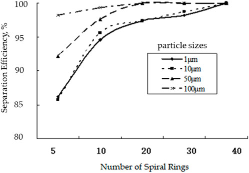
FIGURE 5. Relation curve between separation efficiency and number of spiral turns.
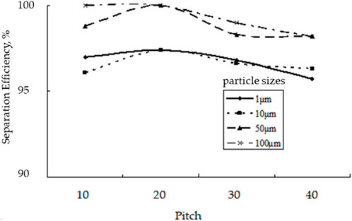
FIGURE 6. Relation curve between separation efficiency and pitch.
Considering the energy consumption and separation efficiency factors, the optimal spiral structure is Case1 while the pitch was 20 mm and the number of spiral turns was 20.
Through the numerical simulation software, eight different schemes were simulated, and it could be seen that scheme five was the optimal structure. In order to further confirm the separation efficiency of this structure, a set of devices had been designed and processed according to the optimal results obtained by numerical simulation analysis, and experimental tests had been carried out to verify the separation efficiency.
To simulate the downhole gas–liquid separation, we used air and water as the medium and used a new type of gas–liquid separator to separate the suspended water particles from the air medium. The separation performance of the gas–liquid separator was tested to compare and verify the numerical simulation results of the flow field.
The test process is shown in Figure 7. In this test, we adopted a new downhole gas–liquid separator which we designed. The test medium is an air-water system. This experimental device mainly consists of four parts: air intake module, liquid inlet and atomization module, separation module and measurement module. The intake module is composed of air compressor, float flowmeter, control valve and pressure gauge and used to provide quantitative gas; The liquid inlet and atomization module is composed of water storage tank, water pump, flow control valve, filter, flow meter, pressure gauge, air-assisted atomization nozzle (the atomization effect in the test is shown in the Supplementary Material); The separation module is shown in Figure 8, which is mainly composed of guide cone, spiral deflector, oil pipe, and casing; The measuring module consists of drainage control valve, measuring cylinder and stopwatch.
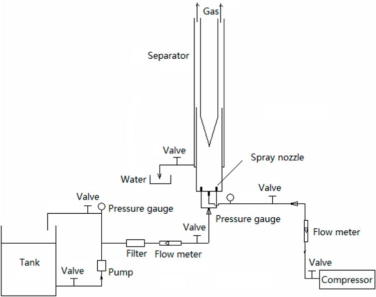
FIGURE 7. Test process.
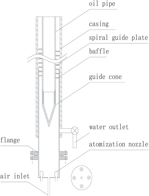
FIGURE 8. Internal structure of spiral separator for indoor experiments.
In order to measure the separation effect of the separator, air and water were used as the media in this laboratory test. The water is supplied by a water pump and atomized by an atomizing nozzle. The compressed air is produced by an air compressor, which enters the separator through the inlet, and the water and air are mixed before entering the spiral guide plate. After entry, the water droplets are separated from the gas phase under the combined action of centrifugal forces, buoyancy, and gravity. The separated water flows towards the casing wall and flows down the liquid converging trough, and is finally discharged by the water outlet. Gas flows in the annulus and escapes from the oil jacket annulus at the top of the gas–liquid separator.
The required test instruments and equipment are shown in Table 6.
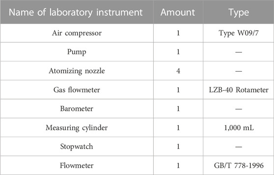
TABLE 6. Test instrument and equipment.
(1) Constant processing quantity
The gas injection pressure in this test is approximately 0.70 MPa, and this processing quantity is kept constant. The gas flow rate in the standard state is 21 m3/h, and the water injection is in the range of 3.8–5.4 m3/h. Different separation efficiency can be obtained by changing the water injection amount. The test results are shown in Figure 9.
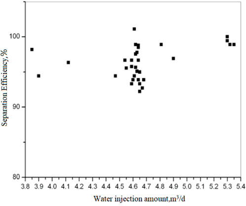
FIGURE 9. Constant gas processing quantity: separation efficiency under different water injection amount.
Test results show that under a condition of constant gas treatment capacity, there is no obvious rule to follow for separation efficiency with the change of the water injection. However, both of them have good gas–water separation effects, and their separation efficiencies are over 90% with an average of approximately 95%.
(2) Variable processing quantity
Under the condition that the water injection amount remains unchanged (approximately 5 m3/h), then the processing quantity is changed. The test results are shown in Figure 10.

FIGURE 10. Separation efficiency changes with gas injection amount.
The effect of the capacity of the separator on the separation efficiency is critical because it determines the strength of the fluid rotation as it enters the separator. Improper processing quantity is not conducive to gas–liquid separation. To achieve effective separation, the fluid must rotate at a higher speed in the separator, so a minimum processing quantity is required according to the working principle of the separator. When the processing quantity is too small, the liquid in the separator cannot establish a sufficiently strong velocity field; then the gas–water separation lacks sufficient power (centrifugal force). This eventually leads to a poor separation effect. As the processing quantity increases, the separation effect generally increases, but if the processing quantity is too large, the speed at which the fluid rotates in the separator is too high, causing the droplet subject to experience greater shear stress and break apart into smaller droplets. This can increase the difficulty of the separation. Therefore, for a specific size of the separator, there should be an optimal flow treatment range.
As can be seen from Figure 10, when the gas injection volume increases, the separation efficiency is slightly decreased, but the separation efficiency is over 90%, which is similar to the numerical simulation and still very efficient.
(1) We used the computational fluid dynamics software FLUENT to numerically simulate the gas–liquid two-phase flow field in a gas–liquid separator under eight different spiral structures. The simulation results were analyzed, and the results show that the more spirals that exist, the longer the separation time of particles in the separator will be, the higher the separation efficiency will be, and the easier the separation process will be. However, the number of spiral turns should not be blindly increased, because the processing cost and energy consumption will also increase. The larger the particle diameter, the greater the mass, and the higher the inertial centrifugal force will be, so it is easier to separate; the smaller the pitch, the higher the flow velocity in the spiral, and the greater the centrifugal inertia force will be, so the separation efficiency has an optimum value for the pitch.
(2) On the basis of numerical simulation analysis and considering the reduction of processing difficulty, we designed and processed the separator with a pitch of 23 mm. The laboratory test shows that the separator has a positive gas–water separation effect under indoor test conditions, and the separation efficiency is over 90%.
(3) Due to the limitations of the measurement range, inherent errors, and the limited test conditions, we cannot simulate the state of downhole high pressure. Therefore, there is a certain amount of error between the simulation results and experimental results, The error occurs because the density of the gas increases under high pressure conditions and the interaction between the gas molecules increases. This can lead to changes in the behavior of the gas within the separator, for example, the gas may interact and dissolve more easily with the liquid than under low pressure conditions. Therefore, the low-pressure test of the gas–liquid separator is the reference basis, because it can provide some basic information about the performance and behavior of gas-liquid separator under specific conditions. The low pressure test allows us to evaluate the separation efficiency, liquid phase content, and other important parameters of the gas-liquid separator at lower pressures. After the low-pressure test, the gas–liquid separator must be tested under the condition of high-pressure.
The original contributions presented in the study are included in the article/Supplementary Material, further inquiries can be directed to the corresponding author.
Conceptualization, CL, ZL, and YZ; data curation, CL and BL; formal analysis, CL and YZ; funding acquisition, ZL and CL; methodology, CL and YZ; project administration, CL and YZ; software, CL and YZ; supervision, ZL and CL; validation, CL and YZ; writing—original draft, CL and YZ; writing—review and editing, CL, ZL, YZ, and BL. All authors contributed to the article and approved the submitted version.
This work was supported by the National Natural Science Foundation of China under Grant No. U22B2073.
The authors declare that the research was conducted in the absence of any commercial or financial relationships that could be construed as a potential conflict of interest.
All claims expressed in this article are solely those of the authors and do not necessarily represent those of their affiliated organizations, or those of the publisher, the editors and the reviewers. Any product that may be evaluated in this article, or claim that may be made by its manufacturer, is not guaranteed or endorsed by the publisher.
The Supplementary Material for this article can be found online at: https://www.frontiersin.org/articles/10.3389/feart.2023.1209743/full#supplementary-material
SUPPLEMENTARY FIGURE S1 | Atomization effect.
SUPPLEMENTARY FIGURE S2 | The separation trajectory of particles with different diameters.
Anderson, K., Zhang, X., and Abbasi, B. (2021). A method to design and optimize axial flow cyclones for gas–liquid separation. J. Fluids Eng. 143 (9). doi:10.1115/1.4050638
Bo, Q., Zhang, Q., Li, B., et al. (2003). Design and analysis of spiral downhole oil-gas separator. China Pet. Mach. 31 (1), 8–10.
Chang, F., and Dhir, V. (1994). Turbulent flow field in tangentially injected swirl flows in tubes. Int. J. heat fluid flow 15 (5), 346–356. doi:10.1016/0142-727x(94)90048-5
Chen, G., Fan, J., Zhang, P., and Wang, W. (2020). Experimental and CFD investigation on effects of internals on the flow pattern and performance of a divergent cyclone separator. J. Taiwan Inst. Chem. Eng. 115, 160–168. doi:10.1016/j.jtice.2020.10.011
Cui, H. (2010). Study on the separation mechanism and performance of spiral gas-liquid separator. Northeast Petroleum University.
Dries, H. W., and Hoffmann, A. C. (2019). A correlation giving improved description of the capacity and efficiency of vane-type gas–liquid separators. AIChE J. 65 (5), e16566. doi:10.1002/aic.16566
El-Emam, M. A., Zhou, L., Shi, W., and Han, C. (2021). Performance evaluation of standard cyclone separators by using CFD–DEM simulation with realistic bio-particulate matter. Powder Technol. 385, 357–374. doi:10.1016/j.powtec.2021.03.006
Fitnawan, E. A., Rivera, R. M., and Golan, M. (2009). “Inclined gravity downhole oil-water separator: Using laboratory experimental results for predicting the impact of its application in high rate production wells,” in Proceeding of the Asia Pacific Oil and Gas Conference and Exhibition, Jakarta, Indonesia, August, 2009 (Richardson, TX: OnePetro).
Fu, J. (2009). Research on downhole gas-liquid separation and reinjection T echnology for gas wells. Dissertation. Dongying: China University of Petroleum.
Gomez, L., Mohan, R., Shoham, O., and Kouba, G. (2000). Enhanced mechanistic model and field-application design of gas/liquid cylindrical cyclone separators. Spe J. 5 (02), 190–198. doi:10.2118/62487-pa
Hafezi, R., Akhavan, A., Pakseresht, S., and Wood, D. A. (2021). Global natural gas demand to 2025: A learning scenario development model. Energy 224, 120167. doi:10.1016/j.energy.2021.120167
Harris, J., Walters, W., and Langhoff, J. (1999). “New downhole gas separator enhances coiled tubing jetting and stimulation procedures,” in Proceeding of the SPE/ICoTA Coiled Tubing Roundtable, Houston, Texas, May, 1999 (Richardson, TX: OnePetro).
Hongyu, Z. (2015). Numerical simulation of flow field in spiral separator. Adv. Petroleum Explor. Dev. 9 (2), 121–125.
Lan, W., Wang, H., Li, Y., Feng, K., Zhang, X., Liu, Y., et al. (2022). Numerical and experimental investigation on a downhole gas-liquid separator for natural gas hydrate exploitation. J. Petroleum Sci. Eng. 208, 109743. doi:10.1016/j.petrol.2021.109743
Le, T. T., Ngo, S. I., Lim, Y.-I., Park, C.-K., Lee, B.-D., Kim, B.-G., et al. (2018). Three-phase Eulerian computational fluid dynamics of air–water–oil separator under off-shore operation. J. Petroleum Sci. Eng. 171, 731–747. doi:10.1016/j.petrol.2018.08.001
Liang, F., Song, L., and Sun, Y. (2015). An experimental investigation of phase separation of gas–liquid two-phase flow through a small break. Chem. Eng. Res. Des. 102, 161–170. doi:10.1016/j.cherd.2015.06.027
Lim, K., Kim, H., and Lee, K. (2004). Characteristics of the collection efficiency for a cyclone with different vortex finder shapes. J. Aerosol Sci. 35 (6), 743–754. doi:10.1016/j.jaerosci.2003.12.002
Liu, Y., Wang, C., Cai, J., Lu, H., Huang, L., and Yang, Q. (2019). Pilot application of a novel Gas–Liquid separator on offshore platforms. J. Petroleum Sci. Eng. 180, 240–245. doi:10.1016/j.petrol.2019.05.001
Liu, S., Zhang, J., Wang, L.-S., and Xu, J.-Y. (2020). Separation mechanism and influential factor study on vane-type-associated petroleum gas separator. Sep. Purif. Technol. 250, 117274. doi:10.1016/j.seppur.2020.117274
Lopez, J., Pereyra, E., and Sarica, C. (2019). “An experimental investigation of dynamic behavior of gravity-driven downhole separators,” in Proceeding of the SPE Annual Technical Conference and Exhibition, Calgary, Alberta, Canada, October, 2019 (Richardson, TX: OnePetro).
Makogon, Y. F. (2010). Natural gas hydrates–A promising source of energy. J. Nat. gas Sci. Eng. 2 (1), 49–59. doi:10.1016/j.jngse.2009.12.004
Meng, L., Gao, S., Wei, D., Cui, B., Shen, Y., Song, Z., et al. (2021). Effects of cross-sectional geometry on flow characteristics in spiral separators. Sep. Sci. Technol. 56 (17), 2967–2977. doi:10.1080/01496395.2020.1853169
Millington, B., and Thew, M. (1987). “LDA study of component velocities in air-water models of steam-water cyclone separators,” in Proceeding of the 3 rd International Conference on Multiphase Flow, The Hague, The Netherlands, 115–125.
Mondt, J. F. (1996). “Aerospace gas/liquid separator for terrestrial applications, IECEC 96,” in Proceedings of the 31st Intersociety Energy Conversion Engineering Conference, Washington, DC, USA, August 1996 (IEEE), 109–113.
Nagdewe, S., Kwoon, J., Kim, H., Kim, D., Kwak, K., and Setoguchi, T. (2008). A parametric study for high-efficiency gas-liquid separator design. J. Therm. Sci. 17, 238–242. doi:10.1007/s11630-008-0238-z
Najafi, S., Hajidavalloo, E., Ghanbarzadeh, A., Gerami, H., and Alavi, S. M. (2020). Performance improvement of helical downhole gas-oil separator using experimental approach. SPE Prod. Operations 35 (03), 510–521. doi:10.2118/201227-pa
Oh, J., Choi, S., Kim, J., Lee, S., and Jin, G. (2014). Particle separation with the concept of uniflow cyclone. Powder Technol. 254, 500–507. doi:10.1016/j.powtec.2014.01.057
Qiu, S., and Wang, G. (2020). Effects of reservoir parameters on separation behaviors of the spiral separator for purifying natural gas hydrate. Energies 13 (20), 5346. doi:10.3390/en13205346
Qiu, S., Wang, G., Zhou, S., Liu, Q., Zhong, L., and Wang, L. (2020). The downhole hydrocyclone separator for purifying natural gas hydrate: Structure design, optimization, and performance. Sep. Sci. Technol. 55 (3), 564–574. doi:10.1080/01496395.2019.1577264
Qu, Z., Zhang, Q., Li, H., et al. (2006). Design of downhole oil-water separation system and study of ground monitoring model. J. Xi'an Shiyou Univ. 21 (3), 34–37.
Qu, Z. Q., Tian, X. L., and Yuan, S. C. (2011). Spiral downhole oil and gas separator design and separation effect analysis. Oil Field Equip. 40 (6), 39–43.
Rosa, E., França, F., and Ribeiro, G. (2001). The cyclone gas–liquid separator: Operation and mechanistic modeling. J. Petroleum Sci. Eng. 32 (2-4), 87–101. doi:10.1016/s0920-4105(01)00152-8
Rui, Y., Lei, Z., and Baojin, Z. (2021). “The structure design and the flow field analysis of the gas-liquid separation cyclone,” in IOP conference series: Earth and environmental science (Bristol, United Kingdom: IOP Publishing), 012080.
Safikhani, H., and Mehrabian, P. (2016). Numerical study of flow field in new cyclone separators. Adv. Powder Technol. 27 (2), 379–387. doi:10.1016/j.apt.2016.01.011
Wang, L., Feng, J., Gao, X., and Peng, X. (2017). Investigation on the oil–gas separation efficiency considering oil droplets breakup and collision in a swirling flow. Chem. Eng. Res. Des. 117, 394–400. doi:10.1016/j.cherd.2016.10.033
Wang, Q., Liu, Y., Yang, J., Cui, M., and Qi, D. (2018). “A novel downhole gas separator in ESP systems,” in Proceeding of the SPE Asia Pacific Oil and Gas Conference and Exhibition, Brisbane, Australia, October, 2018 (Richardson, TX: OnePetro).
Wang, Y., Chen, J., Yang, Y., Han, M., Zhou, Y., Ye, S., et al. (2021). Experimental and numerical performance study of a downward dual-inlet gas-liquid cylindrical cyclone (GLCC). Chem. Eng. Sci. 238, 116595. doi:10.1016/j.ces.2021.116595
Wasilewski, M. (2017). Analysis of the effect of counter-cone location on cyclone separator efficiency. Sep. Purif. Technol. 179, 236–247. doi:10.1016/j.seppur.2017.02.012
Wei, Q., Sun, G., and Gao, C. (2020). Numerical analysis of axial gas flow in cyclone separators with different vortex finder diameters and inlet dimensions. Powder Technol. 369, 321–333. doi:10.1016/j.powtec.2020.05.038
Weingarten, J., Kolpak, M., Mattison, S., and Williamson, M. (1997). Development and testing of a compact liquid-gas auger partial separator for downhole or surface applications. SPE Prod. Facil. 12 (01), 34–40. doi:10.2118/30637-pa
Xiaoming, L., Qifeng, G., Meng, L., Lulu, Y., and Limin, H. (2020). Separation characteristics of axial-flow cyclone separator. Acta Pet. Sin. Pet. Process. Sect. 36 (3), 592.
Xu, B., Zhang, X., Zhao, L., Jiang, M., Liu, L., and Xia, H. (2021). Structure design and preliminary experimental investigation on oil-water separation performance of a novel helix separator. Sep. Sci. Technol. 56 (15), 2680–2691. doi:10.1080/01496395.2020.1837874
Zeng, X., Zhao, L., Fan, G., and Yan, C. (2021). Numerical and experimental study on a new axial separator for liquid-liquid separation. J. Taiwan Inst. Chem. Eng. 123, 104–114. doi:10.1016/j.jtice.2021.05.037
Zhou, G., Ling, X., and Tu, S. (2004). Numerical simulation and experimental research on separation performance of spiral vane diversion separator. J. Chem. Ind. Eng. 55, 1821–1826.
Zhou, F., Sun, G., Han, X., Zhang, Y., and Bi, W. (2018). Experimental and CFD study on effects of spiral guide vanes on cyclone performance. Adv. Powder Technol. 29 (12), 3394–3403. doi:10.1016/j.apt.2018.09.022
Zhou, W., E, C., Li, Z., and Lu, C. (2020). Separation characteristics in a novel gas–liquid vortex separator. Industrial Eng. Chem. Res. 59 (40), 18115–18125. doi:10.1021/acs.iecr.0c03319
Keywords: spiral separator, particle diameter, number of spiral turns, pitch, numerical simulation
Citation: Li C, Li Z, Zhang Y and Li B (2023) Numerical simulation and experimental study of two-phase flow in downhole spiral gas-liquid separator. Front. Earth Sci. 11:1209743. doi: 10.3389/feart.2023.1209743
Received: 21 April 2023; Accepted: 02 June 2023;
Published: 12 July 2023.
Edited by:
Wei Zhang, Sichuan University, ChinaReviewed by:
Jisheng Kou, Shaoxing University, ChinaCopyright © 2023 Li, Li, Zhang and Li. This is an open-access article distributed under the terms of the Creative Commons Attribution License (CC BY). The use, distribution or reproduction in other forums is permitted, provided the original author(s) and the copyright owner(s) are credited and that the original publication in this journal is cited, in accordance with accepted academic practice. No use, distribution or reproduction is permitted which does not comply with these terms.
*Correspondence: Chenghua Li, bGNoQHVwYy5lZHUuY24=
Disclaimer: All claims expressed in this article are solely those of the authors and do not necessarily represent those of their affiliated organizations, or those of the publisher, the editors and the reviewers. Any product that may be evaluated in this article or claim that may be made by its manufacturer is not guaranteed or endorsed by the publisher.
Research integrity at Frontiers
Learn more about the work of our research integrity team to safeguard the quality of each article we publish.