 Zilin Zhang1,2
 Lianchong Li
95% of researchers rate our articles as excellent or good
Learn more about the work of our research integrity team to safeguard the quality of each article we publish.
Find out more
ORIGINAL RESEARCH article
Front. Earth Sci. , 13 July 2023
Sec. Geohazards and Georisks
Volume 11 - 2023 | https://doi.org/10.3389/feart.2023.1193205
This article is part of the Research Topic Instability Mechanism and Disaster Prevention of the Jointed Rockmass View all 11 articles
Laminar argillaceous limestone continental shale is an important oil reservoir in Jiyang Depression, Bohai Bay Basin of China. Affected by the laminar structure, the spatial propagation morphology of hydraulic fracturing is not clear. To reveal the propagation law of hydraulic fracturing pathway in laminar marl continental shale, the mineral content and basic rock mechanics test are firstly carried out on the cores from the wells in Jiyang Depression. Secondly the similar material cores with standard-size and large-size are manufactured and processed. Finally, combined with physical model experiments, acoustic emission and moment tensor inversion techniques, the hydraulic fracturing experiments on the large-size cores under different stress differences are conducted. The experimental results show that the in situ stress (confining stresses), laminar structure, and lithological distribution jointly affect the propagation mode of fractures. As the horizontal stress difference increases, the stimulated reservoir volume gradually decreases, and the number of shear fractures decreases accordingly. Macroscopically, the pump pressure curve shows obvious fluctuation in the case with lower horizontal stress difference, which is the external performance of hydraulic fracture initiation–obstruction–turning–penetrating–obstruction–turning. The content of brittle and plastic minerals has a significant impact on the fracture complexity, particularly the layers with high argillaceous content have a significant inhibitory effect on fracture propagation. The weakly cemented lamination or bedding plane is easy to capture the fracture and make it propagate along the bedding plane, thereby increasing the complexity of fracture network. The research results are expected to provide a theoretical reference for design and optimization of hydraulic fracturing parameter in continental shale oil exploration and development.
The favorable lithofacies of the continental shale in Jiyang depression mostly consists of laminated argillaceous limestone. The reservoir is mainly located in Es2, Es3, and Es4 sections with carbonate content as the primary brittle mineral. The brittle mineral generally incorporates brittle mineral more than 60% in content. The test development of continental shale reservoir in the early stage in Shengli Oilfield showed that the pump pressure in field fluctuated significantly, and there is also a significant difference in the amount of sand added to each fracturing section. The reason for these phenomena has not yet been fully clarified.
As a complex lithofacies, shale shows significant anisotropy, with a complex failure pattern greatly impacted by stress difference (Vasin et al., 2013; Wu et al., 2016; Weijermars et al., 2020). Stanchits et al. (2015); Li et al. (2018); Jiang et al. (2020) adopted acoustic emission (AE) and tracer to conduct the hydraulic fracturing test on the thick interlayer, and analyzed the pump pressure curve and AE signal from the perspective of energy. Based on the analysis of the mineral content in shale, (Zhang et al., 2016; Hattori et al., 2017) found that the high brittleness were more likely to lead to more multi-branch and turning fractures under the external load. Zhao et al. (2014); Dan et al. (2015) investigated the sensitivity of each influencing factor due to the pattern of hydraulic fracture propagation when the process pipeline and shale lamination formed different angles. Taghichian et al. (2014); Garcia-Teijeiro et al. (2016); Ju et al. (2020) studied the cracking behaviors such as the approaching, shearing, penetrating, and steering of the hydraulic fractures caused by the induced stress in the crack tip. It has been pointed out that the mechanical parameters and brittleness difference resulting from the physical anisotropy of shale reservoir had a significant impact on the selection of fracturing block and optimization of hydraulic fracturing parameter (Rogers et al., 2010; Thomsen, 2013; Almutairi, 2014; Ghahfarokhi, 2017). Weijers et al. (2000); McClure and Horne (2013); Lu et al. (2015); Ju et al. (2019) optimized the fracturing parameter using numerical simulation and found that the stimulated reservoir volume (SRV) and oil–gas production after fracturing are closely positively correlated. With the improvement of experimental technology, some scholars have carried out many new experiments on hydraulic fracturing in recent years, including experiments with new similar materials (Abe et al., 2021; Wang et al., 2021; Zhai et al., 2021; Yang et al., 2022; Zheng et al., 2022).
To further reveal the influence of the laminar structure on spatial morphology of fracture propagation, in this study, the mineral content and basic rock mechanics test are firstly carried out on the cores from the wells in Jiyang Depression. Secondly the similar material cores with standard-size and large-size are manufactured and processed. Finally, combined with physical model experiments, acoustic emission and moment tensor inversion techniques, the hydraulic fracturing experiments on the large-size cores under different stress differences are conducted.
The continental shale cores in this study were taken from well X1 4221 m in depth, well X2 3653.1 m in depth, well X3 3678 m in depth and well X4 3054.2 m in depth in Shengli Oilfield. The marl content of each core was calculated by XRD technique. Uniaxial compression strength and tensile strength of cores were tested by Rockman rock mechanics experimental machine.
X-ray diffraction (XRD) technology was used to test the mineral content of typical cores as shown in Figure 1. According to the 2θ-d conversion table, as shown in Figure 2, the corresponding minerals of d value at each peak point were found in order to determine the mineral composition content, and the whole-rock mineral analysis results were obtained. The content of each argillo–calcareous core are shown in Table 1. Although the mineral composition of rock core is not a mechanical parameter, the experiment in this section provides a basic reference for the subsequent preparation of artificial rock cores, as the content of brittle and plastic minerals in the argillaceous limestone continental shale has a significant impact on the complexity of fracturing fractures. When preparing artificial rock cores in subsequent Section 3, it is necessary to refer to the proportion of clay and limestone mineral content.

FIGURE 1. Laminar argillaceous limestone cores.
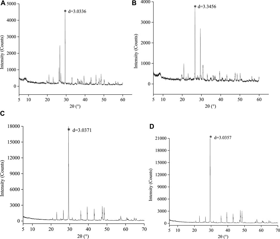
FIGURE 2. XRD mineral content characteristic value d of cores (A) Core form well X1, (B) Core form well X2, (C) Core form well X3, and (D) Core form well X4.
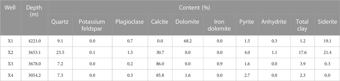
TABLE 1. Mineral content analysis of the cores.
Calcareous minerals were mainly dolomite and calcite, with few other carbonate materials, while argillaceous minerals were mainly clay, with a small amount of quartz, potassium feldspar, and plagioclase. A higher content of calcareous minerals leads to stronger brittleness, making it more likely to be fracture initiation and thus form complex fracture network; a higher content of argillaceous minerals leads to stronger plasticity, making it less likely to be fracture initiation and thus form simple flat fracture. As observed, the calcareous content could be as large as 50%–80% and each core had great difference in its mineral content. Thus, relying on merely the mineral content would be helpful to fully classify and assess the brittleness and compressibility core or reservoir.
The above shale cores were processed into cylindrical cores with 50 mm in diameter and 25 mm in height in the laboratory. Four cores were selected to conduct uniaxial compression test. Figure 3 is the cores and the corresponding stress-strain curves. The experimental results show there is a good consistency between the strength characteristics of rock cores and mineral content. The strength of limestone is significantly higher than that of clay rock, and its brittleness is also significantly better than that of argillaceous rock, which indicates that the complexity of hydraulic fractures in limestone may be higher. The purpose of the mechanical parameters analysis of rock core is to provide a basic reference for subsequent artificial core parameters, to ensure that the mechanical parameters of artificial cores do not deviate significantly.
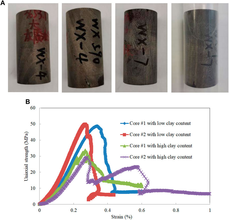
FIGURE 3. Limestone cores (low clay content) and argillaceous cores (high clay content) (A) The cores for uniaxial compression experimental test, and (B) Stress-strain curves.
The core was also processed into a standard cylinder with 25 mm in diameter and 12.5 mm in height. Corresponding to the uniaxial compression test above, three cores from Well X2 in 3653.1 m depth were selected to conduct Brazilian splitting test. The test results are shown in Figure 4 and Table 2. As shown in Figure 4, the core tensile failure occurred along the bedding plane. Shale cores all showed multiple fracture surfaces, implying that most lamina or bedding plane has low cementation strength. During hydraulic fracturing, weakly cemented stratification tended to “capture” fractures and cause them to spread along the stratification interface, thus increasing fracture bandwidth and constraining fracture propagation in the direction of fracture height. If the hydraulic fracture was needed to effectively connect the reservoir area longitudinally, it was suggested to adopt construction measures with large pump rate and high viscosity to promote the propagation of the fracture height.
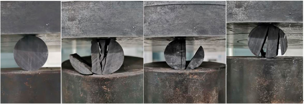
FIGURE 4. Shale cores before and after Brazil splitting.
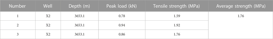
TABLE 2. Brazilian splitting test results of shale core.
Due to the difficulty in collecting large-size deep cores in situ (Sharifigaliuk et al., 2021), this study utilized similar materials to setup rock cores and perform hydraulic fracturing test.
Before pouring large-sized rock cores, standard cylindrical rock cores were also poured to determine the mechanical parameters of similar materials. In general, 32.5 Portland cement, 20–40 mesh quartz sand, 325 mesh Kaolin (China Clay), and water were used for artificial core production. Figure 5 shows the standard cylindrical rock cores of similar materials poured. Correspondingly, their rock mechanics parameters are tested on the Rockman rock mechanics machine. Cores of similar materials after testing are shown in Figure 6. The summarized mechanical parameters of similar material cores and in situ continental shale cores are listed in Table 3. The modulus and strength parameters of the two types of rock cores basically meet the similarity criteria. After several times of matching, the ratio of cement, sand, and Kaolin in the similar materials for limestone is 2:2:1, and the ratio of cement, sand, and Kaolin in the similar materials for argillaceous rock is 1:1:3. In addition, the antifoaming agent accounted for about 1%.
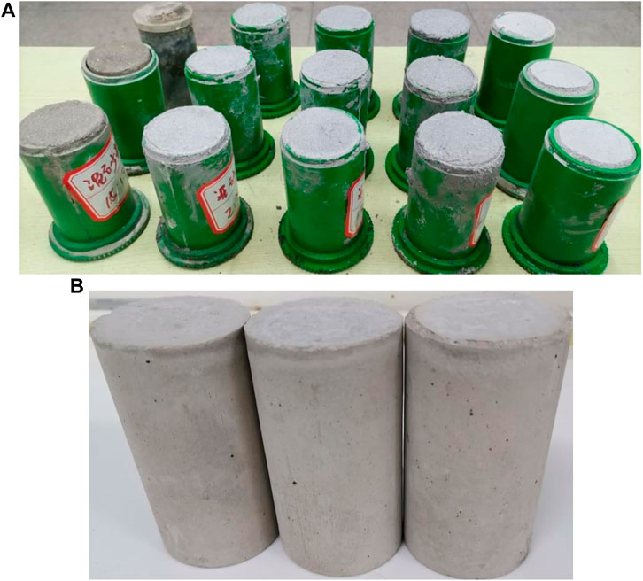
FIGURE 5. Standard size artificial cores (A) before demoulding (B) after demoulding.
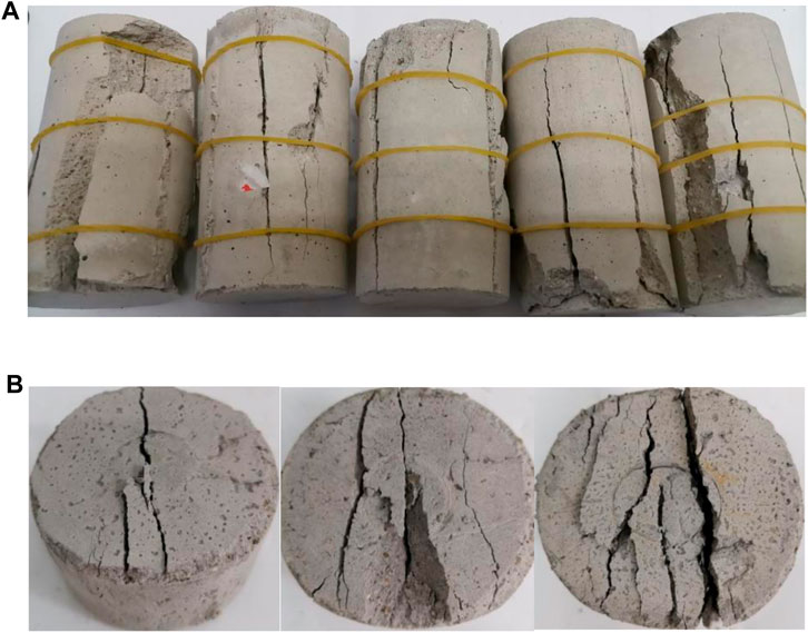
FIGURE 6. Artificial rock cores after experiment (A) Uniaxial compression (B) Brazilian splitting.
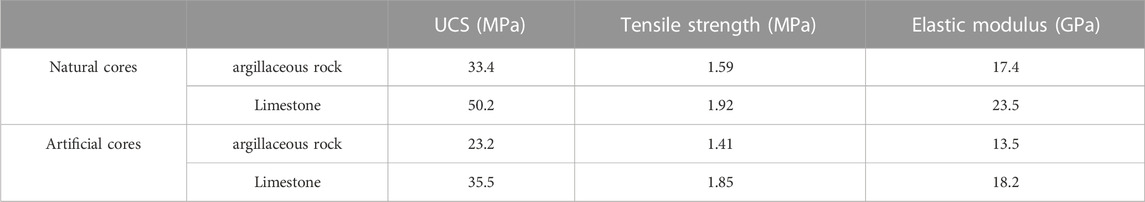
TABLE 3. Comparison of mechanical parameters between natural core and artificial core.
After determining the ratio of similar materials, large-sized rock cores are poured. The cubic laminated core with the size of 300 × 300 × 300 mm3 was poured. The bottom of the material required a shaking table while the upper part of the vibrator to remove foam. The casting process and parameters of the core are presented in Figure 7. The experimental process includes the following steps, i.e., oiling the mold surfaces, filling the mold, vibrating inside, vibrating outside, smoothing the surfaces, and presetting the wellbore. In the actual pouring process, the limestone layer and argillaceous layer are alternately laid, which means a certain thickness of ash layer is laid first, followed by a 1 cm thickness of argillaceous layer, and then a limestone layer is laid, repeating the above process. In the whole process, controlling the overall volume content of mudstone (about 30%) is needed. Moreover, the laying time interval between layers should not exceed 10 min, which not only prevents complete hardening and layering between the layers, but also allows for slight intrusion of adjacent layers, making them to be a complete entity. A total of 6 cores were poured.
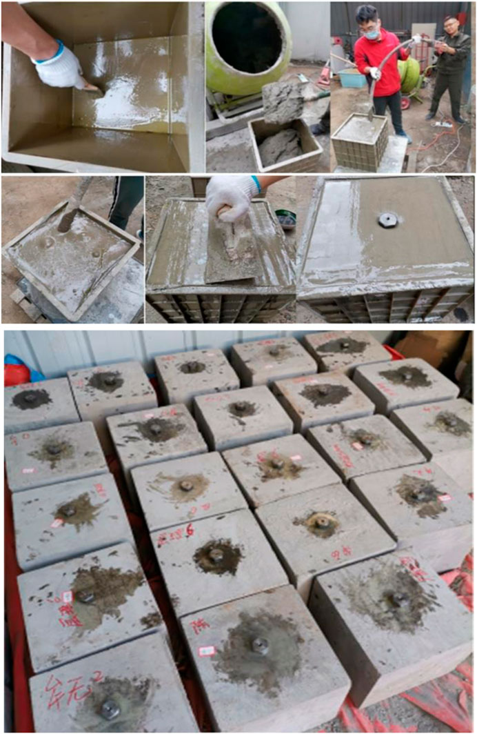
FIGURE 7. Pouring process of similar material cores for hydraulic fracturing test.
The hydraulic fracturing simulation test was conducted on a self-developed true triaxial hydraulic fracturing test system, as illustrated in Figure 8. The system consists of three main parts, i.e., 1) a true triaxial servo loading system, 2) a fluid injection servo control system, and 3) a automatic data acquisition and processing system, as shown in Figure 8A. A cubic specimen with maximum allowable dimensions of 300 mm is placed in the test frame surrounded by pressurizing pistons. The confining stresses were loaded independently using the true triaxial assembly. The confining stresses could be loaded up to 10 MPa. The fiuid injection servo control system was used to accurately determine the injection rate and injection pressure. The maximum injection rate and injection pressure are 10 mL/min and 40 MPa, respectively. Figures 8B,C shows how to attach AE probes and placing the specimen into triaxial servo loading system. The acoustic emission (AE) monitoring system, manufactured by an American acoustic company, was applied to analyze the focal mechanism of hydraulic fracture, as presented in Figure 9.
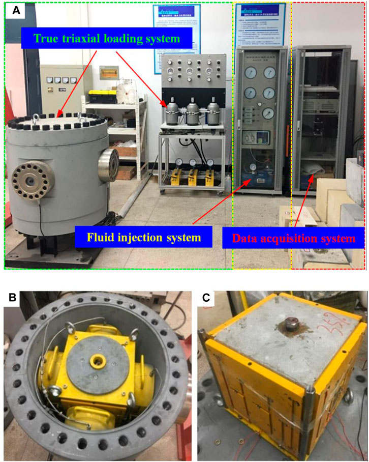
FIGURE 8. True triaxial hydraulic fracturing test system (A) the general machine configuration, (B) attaching AE probes, and (C) placing the specimen into triaxial servo loading system.
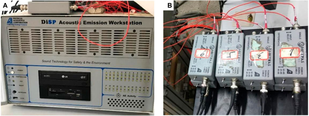
FIGURE 9. The acoustic emission monitoring system (A) AE workstation and (B) amplifier.
Triaxial confining pressures were set as vertical stress σv, maximum horizontal principal stress σH, and minimum horizontal principal stress σh, respectively. In this study, the confining pressures were 10-8-2 MPa in group A, 10-6-2 MPa in group B, and 10-4-2 MPa in group C, respectively. Each group contains two cores. There are a total of six cores in this experiment. To simulate fluid injection, a single cluster perforating fracture pipe was embedded with an inner diameter of 20 mm. The fracturing fluid was water and the pump inject rate is 10 mL/min until the pump was stopped without a significant change in pressure. In the whole process, 8 AE probes were used in the AE monitoring system to obtain the AE signals associated with the initiation and extension of the HFs. In this study, AE monitoring was conducted for each core in the fracturing test. AE probes were laid out, as shown in Figure 10. The lower left corner was the coordinate origin (0, 0, 0), and the coordinate points were (200, 200, 300), (100, 100, 300), (200, 0, 200), (100, 0, 100), (200, 100, 0), (100, 200, 0), (200, 100, 300), (100, 200, 300). The coordinate unit is mm.
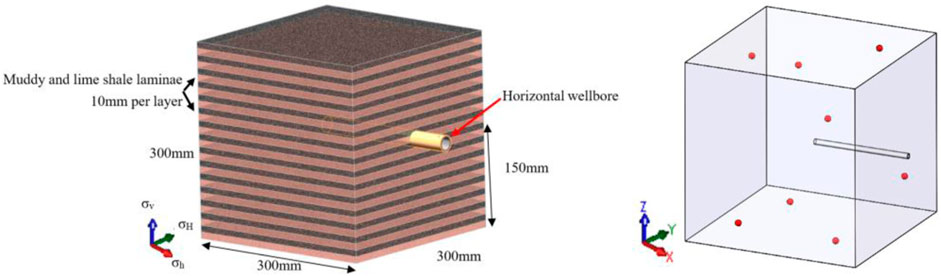
FIGURE 10. Core configuration and acoustic emission detection point layout.
With the application of the AE test system to collect the information and comparing probe information triggered at the same time, it helps to better understand damage, fracture initiation, and propagation in the core. Through the effective AE event loci and waveform analysis, the initial amplitude is calculated. Then moment tensor Inversion is used to analyze specific tensile and shear failure patterns. Considering the similarity with seismology, the moment tensor theory is introduced into acoustic emission test to judge the fracture failure mode in the rock core. The force at the rupture source is decomposed into an isotropic source, a dual couple source, and a compensated linear dipole. Based on moment tensor inversion, the various components of the source mechanism are obtained. Consequently shear and tensile failure are judged based on the corresponding components and their proportions (Shi et al., 2018). AE monitoring results after hydraulic fracturing were inverted by moment tensor, as shown in Figure 11. In these figures, blue dots represent shear failure, red dots represent tensile failure, and green dots represent mixed failure. As the horizontal stress difference decreased, AE events increased, and the fracture modes became more complex. Besides, the fracture types (shear, tensile and mixed failure) also reflect a trend, i.e., with the increase in the horizontal stress difference, the shear fracture ratio significantly decreased. The volume enveloped by AE event points in the fracturing process was regarded as the reconstructed volume SRV, and the relationship between stress difference-SRV-shear fracture ratio is shown in Figure 12. SRV is a statistical value, specifically, SRV is the three-dimensional envelope space of each discrete acoustic emission event. Due to the fact that the SRV is significantly small in physical model experiments, normalization was performed on the SRV. The curves show that, although the experimental data has slight discreteness, the trend of changes in SRV is consistent. As the horizontal stress difference increases, the SRV gradually decreases, and the number of shear fractures decreases accordingly.
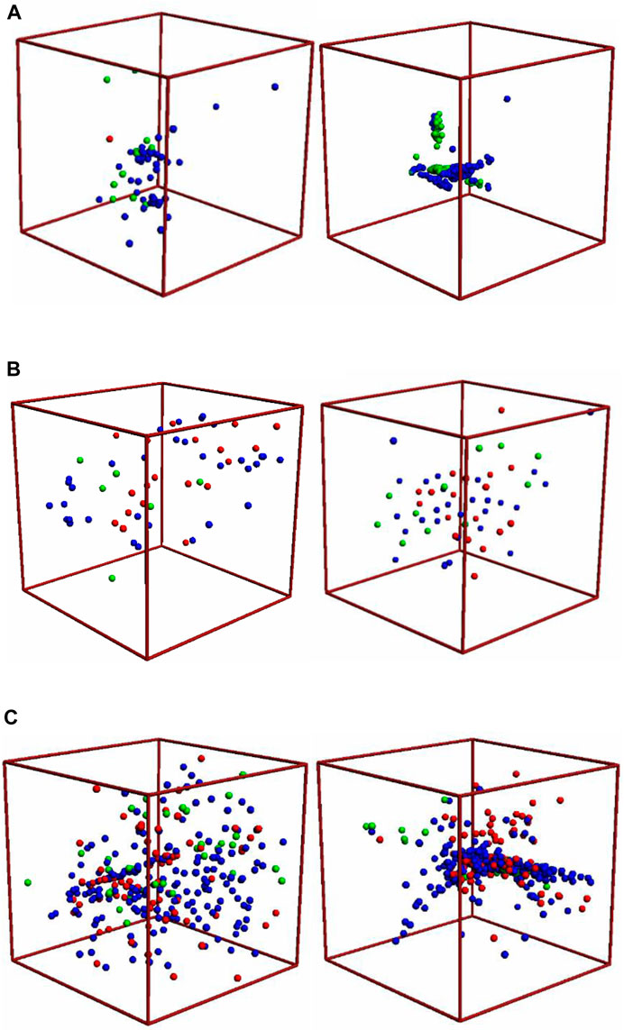
FIGURE 11. Inversion of acoustic emission moment tensor of the cases under different stress differences (A) Group A with confining pressure 10,8,2 MPa, (B) Group B with confining pressure 10, 6, 2 MPa, and (C) Group C with confining pressure 10, 4, 2 MPa.
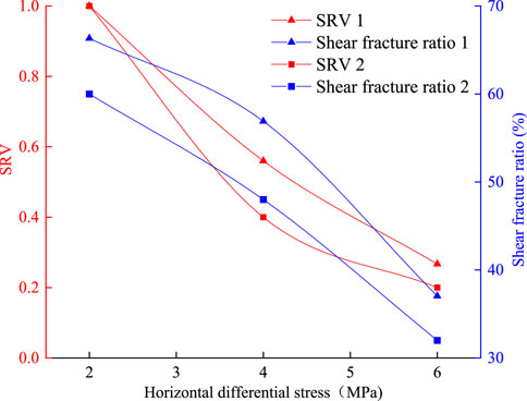
FIGURE 12. The relationship among stress difference, SRV and shear fracture ratio.
The corresponding hydraulic fracturing pump pressure curves are given in Figure 13. As observed, with the decrease in the horizontal stress difference, the pressure shows multiple peaks, the fracture becomes more complex, and the pressure curve shows obvious fluctuation. The intrinsic reason could be that the fracture keeps repeating the propagation process of “initiation–obstruction–turning–penetrating–obstruction–turning”. Once the initiating fracture encounters argillaceous rock layer, the fracture is obstructed and has to propagate along the interface. After propagating a certain distance along the argillo–calcareous laminate interface, the hydraulic fracture could turn again and continue to propagate along the direction of maximum horizontal principal stress. Small fluctuations in pump pressure curve were caused by fracturing fluid passing through the lamina. In the calcareous or limestone layer, the permeability was relatively high. As the fracturing fluid was injected, the pressure gradually increased and reached the pressure required for crossing the layer again, which would propagate again. If there is more fracture turning, there will be more shear fractures, which is consistent with the acoustic emission response in Figure 11.
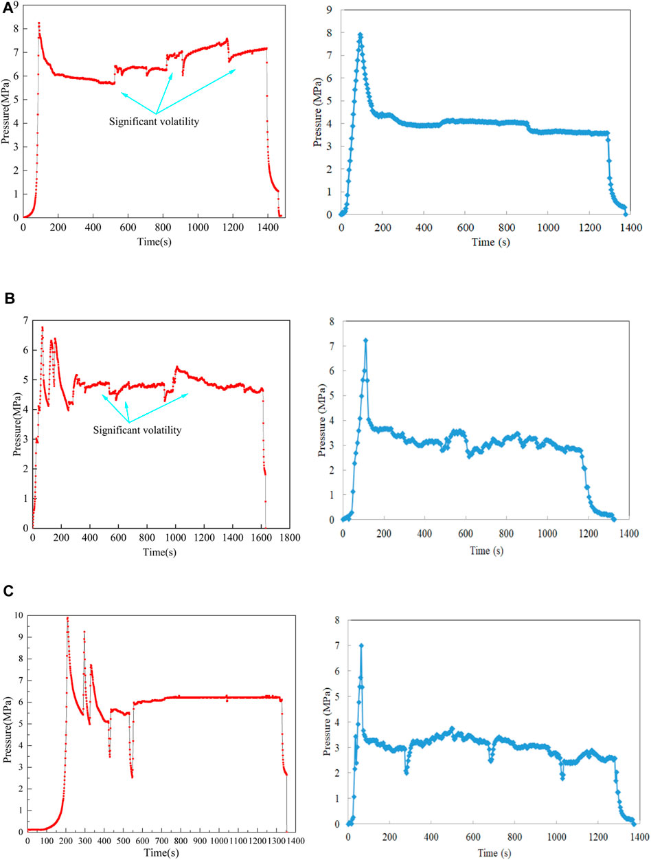
FIGURE 13. Hydraulic fracturing pump pressure curves under different stress differences (A) Group A with confining pressure 10,8,2 MPa (B) Group B with confining pressure 10, 6, 2 MPa and (C) Group C with confining pressure 10, 4, 2 MPa.
To confirm the above conjecture, one core from Group B was manually cut into slices. Figure 14 shows that the tracer magenta has obvious diffusion in the fracture development zone. After fracture reconstruction, the fracture morphology exhibits multiple groups of parallel fractures, and deflection occurs at the heterogeneous point at the interface of argillo–calcareous material, particularly the rock layers with high argillaceous content have a significant inhibitory effect on fracture propagation. Therefore, the height of fracture is relatively small. These observed fracture propagation modes in laboratory tests were the internal cause of obvious pressure fluctuation in different marl sections.
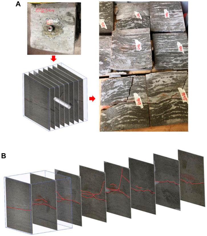
FIGURE 14. Hydraulic fracture reconstruction (A) manually cut slices, and (B) fracture reconstruction.
In situ stress (confining stresses in the experimental test) definitely has an important impact on fracture propagation, but it is not the only factor affecting fracture formation. In addition to the injection rate and viscosity of the fracturing fluid, from the data of this experiment alone, it can be reflected that the following factors also have a significant impact on fracturing mode.
(1) Based on the fluctuation characteristics of fracture types and pressure curves, it can be recognized that the content of argillaceous rock and limestone may have a significant impact on the fracture path, especially in the case of high limestone content, which may be more conducive to the complexity of fractures. Argillaceous layer are generally believed to have strong plasticity and are not conducive to fracture propagation.
(2) The lamination or bedding plane has a significant impact on fracture propagation. Although it is not possible to achieve high-density bedding when making the similar materials rock cores, the influence of bedding on fractures has been fully demonstrated, especially with a significant inhibitory effect on fracture height, as shown in Figure 14. In subsequent research, it can be attempted to use full-size natural cores to conduct experiment on the influence of high-density interlayers on fracture propagation paths.
(3) Multiple perforation clusters may slightly alter the overall pattern of fracture network. Although the stress shadow effect has become less important in the current popular design of close cut fracturing, the injection energy and its distribution of fracturing fluid in the case of multiple cluster perforations can change the ability of fractures to propagate along the bedding plane and pass through the argillaceous layer.
Based on hydraulic fracturing experiments with artificial rock cores, the following conclusions can be drawn.
In situ stress (confining stresses in the experimental test) definitely has an important impact on fracture propagation. As the horizontal stress difference increases, the SRV gradually decreases, and the number of shear fractures decreases accordingly. In the case with higher horizontal stress difference, the fractures are not easy to slide and turn. If there is more fracture turning, there will be more shear fractures, which is consistent with the acoustic emission response.
Although the mineral composition of rock core is not a mechanical parameter, the content of brittle and plastic minerals in the argillaceous limestone continental shale has a significant impact on the fracture complexity, particularly the rock layers with high argillaceous content have a significant inhibitory effect on fracture propagation. In addition, with the characteristics of high permeability and low cementation strength, the lamination or bedding plane also combines with lithology to jointly affect the propagation mode of fractures, especially the evolution of fracture height.
The raw data supporting the conclusion of this article will be made available by the authors, without undue reservation.
ZZ, writing original draft. AZ, data curation. FY, formal analysis. LZ, investigation ML, methodology LC, formal analysis LL,writing—review and editing. All authors contributed to the article and approved the submitted version.
Authors ZZ, AZ, FY, LZ, and ML were employed by the company Shengli Oilfield Branch Company SINOPEC.
The remaining authors declare that the research was conducted in the absence of any commercial or financial relationships that could be construed as a potential conflict of interest. The authors declare that this study received funding from China Petroleum & Chemical Corporation Technology Development Project, grant number 30200019-22-ZC0699-0019. The funder had the following involvement in the study: the funder provided the original rock cores of continental shale.
All claims expressed in this article are solely those of the authors and do not necessarily represent those of their affiliated organizations, or those of the publisher, the editors and the reviewers. Any product that may be evaluated in this article, or claim that may be made by its manufacturer, is not guaranteed or endorsed by the publisher.
Abe, A., Kim, T. W., and Roland, N. (2021). Laboratory hydraulic stimulation experiments to investigate the interaction between newly formed and preexisting fractures. Int. J. Rock Mech. Min. Sci. 141, 104665. doi:10.1016/j.ijrmms.2021.104665
Almutairi, A. (2014). In evaluation of the impact of scale on the well test behaviour of fissured reservoirs (Single-Phase), international discrete fracture newwork engineering conference. Canada: Vncouver. Vncouver, Canada.
Dan, X., Ruilin, H., Wei, G., and Jiaguo, X. (2015). Effects of laminated structure on hydraulic fracture propagation in shale. Petroleum Explor. Dev. 42 (4), 573–579. doi:10.1016/s1876-3804(15)30052-5
Garcia-Teijeiro, X., Rodriguez-Herrera, A., and Fischer, K. (2016). The interplay between natural fractures and stress as controls to hydraulic fracture geometry in depleted reservoirs. J. Nat. Gas Sci. Eng. 34, 318–330. doi:10.1016/j.jngse.2016.06.049
Ghahfarokhi, P. K. (2017). The structured gridding implications for upscaling model discrete fracture networks (DFN) using corrected Oda's method. J. Petroleum Sci. Eng. 153, 70–80. doi:10.1016/j.petrol.2017.03.027
Hattori, G., Trevelyan, J., Augarde, C. E., Coombs, W. M., and Aplin, A. C. (2017). Numerical simulation of fracking in shale rocks: Current state and future approaches. Archives Comput. Methods Eng. 24 (2), 281–317. doi:10.1007/s11831-016-9169-0
Jiang, Z., Li, Q., Hu, Q., Liang, Y., Xu, Y., Liu, L., et al. (2020). Acoustic emission characteristics in hydraulic fracturing of stratified rocks: A laboratory study. Powder Technol. 371, 267–276. doi:10.1016/j.powtec.2020.05.050
Ju, Y., Li, Y., Wang, Y., and Yang, Y. (2020). Stress shadow effects and microseismic events during hydrofracturing of multiple vertical wells in tight reservoirs: A three-dimensional numerical model. J. Nat. Gas Sci. Eng. 84, 103684. doi:10.1016/j.jngse.2020.103684
Ju, Y., Wang, Y., Xu, B., Chen, J., and Yang, Y. (2019). Numerical analysis of the effects of bedded interfaces on hydraulic fracture propagation in tight multilayered reservoirs considering hydro-mechanical coupling. J. Petroleum Sci. Eng. 178, 356–375. doi:10.1016/j.petrol.2019.03.049
Li, N., Zhang, S., Zou, Y., Ma, X., Zhang, Z., Li, S., et al. (2018). Acoustic emission response of laboratory hydraulic fracturing in layered shale. Rock Mech. Rock Eng. 51 (11), 3395–3406. doi:10.1007/s00603-018-1547-5
Lu, Q., Guo, J., Zhu, H., and Zhao, X. (2015). “Cluster spacing optimization based on a multi-fracture simultaneous propagation model,” in SPE/IATMI asia pacific oil & gas conference and exhibition (United States: OnePetro).
McClure, M. W., and Horne, R. N. (2013). Discrete fracture network modeling of hydraulic stimulation_ coupling flow and geomechanics. Germany: Springer.
Rogers, S., Elmo, D., Dunphy, R., and Bearinger, D. (2010). In Understanding hydraulic fracture geometry and interactions in the Horn River Basin through DFN and numerical modeling. OnePetro: Canadian Unconventional Resources and International Petroleum Conference.
Sharifigaliuk, H., Mahmood, S. M., Ahmad, M., and Rezaee, R. (2021). Use of Outcrop as substitute for subsurface shale: Current understanding of similarities, discrepancies, and associated challenges. Energy & Fuels 35 (11), 9151–9164. doi:10.1021/acs.energyfuels.1c00598
Shi, P., Angus, D., Nowacki, A., Yuan, S., and Wang, Y. (2018). Microseismic full waveform modeling in anisotropic media with moment tensor implementation. Surv. Geophys. 39 (4), 567–611. doi:10.1007/s10712-018-9466-2
Stanchits, S., Burghardt, J., and Surdi, A. (2015). Hydraulic fracturing of heterogeneous rock monitored by acoustic emission. Rock Mech. Rock Eng. 48 (06), 2513–2527. doi:10.1007/s00603-015-0848-1
Taghichian, A., Zaman, M., and Devegowda, D. (2014). Stress shadow size and aperture of hydraulic fractures in unconventional shales. J. Petroleum Sci. Eng. 124, 209–221. doi:10.1016/j.petrol.2014.09.034
Thomsen, L. (2013). In on the use of isotropic parameters to understand anisotropic shale behavior: 83rd annual international meeting, SEG, expanded abstracts. Abstract 2013, 320–324.
Vasin, R. N., Wenk, H.-R., Kanitpanyacharoen, W., Matthies, S., and Wirth, R. (2013). Elastic anisotropy modeling of Kimmeridge shale. J. Geophys. Research-Solid Earth 118 (8), 3931–3956. doi:10.1002/jgrb.50259
Wang, J., Xie, H., and Li, C. (2021). Anisotropic failure behaviour and breakdown pressure interpretation of hydraulic fracturing experiments on shale. Int. J. Rock Mech. Min. Sci. 142, 104748. doi:10.1016/j.ijrmms.2021.104748
Weijermars, R., Wang, J., and Nelson, R. (2020). Stress concentrations and failure modes in horizontal wells accounting for elastic anisotropy of shale formations. Earth-Science Rev. 200, 102957. doi:10.1016/j.earscirev.2019.102957
Weijers, L., Wright, C., Sugiyama, H., Sato, K., and Zhigang, L. (2000). “Simultaneous propagation of multiple hydraulic fractures-evidence, impact and modeling implications,” in International oil and gas conference and exhibition in China (United States: OnePetro).
Wu, Z., Zuo, Y., Wang, S., Yi, T., Chen, S., Yu, Q., et al. (2016). Numerical simulation and fractal analysis of mesoscopic scale failure in shale using digital images. J. Petroleum Sci. Eng. 145, 592–599. doi:10.1016/j.petrol.2016.06.036
Yang, W., Huang, C., Zhang, Y., Lv, X., Yu, R., and Yao, J. (2022). Study on the influence of stress differences on hydraulic fracturing based on true triaxial experiments and discrete element numerical simulations. Geomech. Geophys. Geo-energ. Geo-resour. 8, 139. doi:10.1007/s40948-022-00449-4
Zhai, H., Chang, X., Zhu, W., Lei, X., and Xue, Z. (2021). Study on anisotropy of Longmaxi shale using hydraulic fracturing experiment. Sci. China Earth Sci. 64 (2), 260–277. doi:10.1007/s11430-020-9691-2
Zhang, D., Ranjith, P. G., and Perera, M. S. A. (2016). The brittleness indices used in rock mechanics and their application in shale hydraulic fracturing: A review. J. Petroleum Sci. Eng. 143, 158–170. doi:10.1016/j.petrol.2016.02.011
Zhao, L., Liu, F., Wang, P., Liu, P., Luo, Z., and Li, N. (2014). A review of creation and propagation of complex hydraulic fracture network. Oil gas Geol. 35 (4), 562–569. doi:10.11743/ogg201417
Keywords: continental shale, hydraulic fracturing, fracture propagation, acoustic emission monitoring, true triaxial experiment
Citation: Zhang Z, Zhong A, Yang F, Zhang L, Lu M, Chai L and Li L (2023) Experimental study on the hydraulic fracture propagation of laminar argillaceous limestone continental shale. Front. Earth Sci. 11:1193205. doi: 10.3389/feart.2023.1193205
Received: 24 March 2023; Accepted: 06 July 2023;
Published: 13 July 2023.
Edited by:
Shuren Wang, Henan Polytechnic University, ChinaReviewed by:
Sheng-Qi Yang, China University of Mining and Technology, ChinaCopyright © 2023 Zhang, Zhong, Yang, Zhang, Lu, Chai and Li. This is an open-access article distributed under the terms of the Creative Commons Attribution License (CC BY). The use, distribution or reproduction in other forums is permitted, provided the original author(s) and the copyright owner(s) are credited and that the original publication in this journal is cited, in accordance with accepted academic practice. No use, distribution or reproduction is permitted which does not comply with these terms.
*Correspondence: Lianchong Li, bGlfbGlhbmNob25nQDE2My5jb20=
Disclaimer: All claims expressed in this article are solely those of the authors and do not necessarily represent those of their affiliated organizations, or those of the publisher, the editors and the reviewers. Any product that may be evaluated in this article or claim that may be made by its manufacturer is not guaranteed or endorsed by the publisher.
Research integrity at Frontiers
Learn more about the work of our research integrity team to safeguard the quality of each article we publish.