 Chenglong Yu1*
 Fengnian Wang
- 1China Academy of Safety Science and Technology, Beijing, China
- 2Shanxi Transportation Technology Research and Development Co., Ltd., Taiyuan, China
- 3School of Earth Sciences and Engineering, Hohai University, Nanjing, China
We present a numerical model for blast-induced seismic waves. This model is based on the transformation mechanism of the seismic wave field, and the process of the seismic wave’s generation is divided into two stages. The first stage is the generation of elastic waves. Due to the plastic deformation of the geotechnical medium in this stage, we have established the Euler model to describe it. The second stage is the prorogation of the elastic waves; we have established the Lagrange models to describe this stage. Finally, the influence of the main parameters of the explosive sources (detonation pressure and expansion index) on the seismic wave is analyzed by the established model. The results show that the proposed model in this paper can reasonably predict the evolution law of the seismic wave field based on the explosive source parameters.
1 Introduction
It is essential to improve seismic resolution, since the seismic exploration has challenges in exploring the smaller, deeper, and thinner targets.
For a long time, physicists have been expected to explain the corresponding relationship between the elastic wave caused by the explosion and the initial conditions, such as the explosive performance and dynamic characteristics of the soil medium, by establishing an equivalent model. Jeffreys (1931) first introduced the operator symbol and operator to solve the one-dimensional cavity vibration problem. The particle displacement caused by the body wave (P wave) and surface wave (S wave) in the spherical impact propagating in the medium changes with time, and the displacement analytical solution of the two waves is obtained. In 1942, Sharpe (1942) observed and recorded the time travel curve of the particle vibration velocity at different positions through a large-scale explosion test in soil and clarified the relationship between some characteristics of the recorded results and the characteristics of explosive seismic sources. According to these experimental results, the equivalent model of the “equivalent cavity” elastic medium was proposed, and many studies conducted later were based on this equivalent cavity model. Goldsmith and Allen (1955) assumed that the elastic medium is isotropic, there is a spherical cavity with a certain radius inside, and the cavity is subjected to the pulse stress in the exponential attenuation form. The function equations of particle displacement, velocity, normal stress, and shear stress with respect to space and time are derived to reflect the propagation law of stress waves in the elastic medium. Friedman et al. (1965) calculated the one-dimensional stress–wave propagation during the expansion of the medium cavity, obtained the analytical expression of the elastic region with respect to time and spatial location parameters, and calculated the particle disturbance caused by the elastic unloading near the cavity when the pressure on the cavity wall decayed exponentially with the spatial location parameter by a “jump” difference scheme. However, the method he proposed becomes unstable as the distance increases. Achenbach and Sun (1966) also studied the effect of the initial cavity size on the explosion in the medium under the assumption that the medium is an elastomer. The stress fields when the cavity wall is not moving and the cavity radius increases with the time parameter alignment are calculated, and the propagation of the stress wave after the cavity stops expanding is discussed. Garg (1968a) changed the pressure load on the cavity under the premise of Friedman operation and gave a more complicated pressure form to calculate the particle stress and particle vibration velocity distribution in the plastic region near the cavity. The results obtained by this method can clearly reflect the spatial distribution of the particle stress and particle vibration velocity near the cavity in a short time. However, this method still requires a complex boundary processing method. In another research by Garg (1968b), the start-up conditions of the computation procedure were improved, which simplified the boundary condition process, and a new pressure attenuation load was applied. The numerical solution obtained by the theoretical method is only applicable to particles with a small time parameter and near the cavity. No detailed calculation methods are given for the more distant medium.
On the basis of the elastic medium, considering the destruction and compression of the soil medium caused by an explosive high-pressure effect, it is very meaningful to introduce the elastic–plastic medium. Ghosh (1968) took the large underground explosion as the premise, assumed that the medium around the cavity was an elastomer, and pointed out that the medium near the cavity should exhibit plastic properties, and there was a plastic wave that propagates outward from the cavity boundary after the elastic wave. Elastoplastic region boundaries also propagated outward at a certain speed. In his article, he assumed two situations: first, the propagation velocity of the elastoplastic boundary is constant, and the pressure load on the cavity boundary is under normal pressure; second, the propagation velocity of the elastoplastic boundary and the pressure load of the cavity boundary decay exponentially with time. The corresponding analytical expression is obtained by solving the displacement field in these two cases. Lyakhov (1964) and LyakhovPolyakova (1967) obtained the relationship between peak overpressure and distance by the closed explosion test of the TNT spherical charge in sand. The results show that the larger the air-to-volume ratio, the smaller the moisture content and the larger the overpressure attenuation velocity. The peak overpressure in the unsaturated soil may be 1/100th of the peak overpressure in the saturated soil. The explosives in unsaturated soil produce a stable shock wave, and the shock wave attenuation becomes the elastic–plastic wave when the overpressure attenuation is 4–12 kg/cm2. Kawasumi and Yosiyama (1935) solved the displacement field of the cavity wall when the spherical pressure load is given by the Fourier’s integral and proved that the simplest reason for the seismic wave is the existence of the initial strain potential energy. It is pointed out that the cavity is subjected to different loads, and the excited damping oscillation form still maintains a certain degree of similarity. G. N. Bycroft (1966) solved the cavity-expansion problem of the semi-infinite space analytically, taking into account the free-surface particle vibration caused by the seismic wave returning to the cavity wall after free-surface reflection and re-reflecting. The particle displacement solution of the free surface with the known expansion velocity of the cavity wall is calculated.
In addition, the pressure time function of the point source is determined according to the far-field vibration waveform and spectral characteristics, and this kind of inversion is also an effective seismic source model to interpret the explosive seismic wave. The pressure load of the equivalent seismic source is the difference between the true stress and the linear elastic model stress, which is essentially different from the “ideal cavity” model. Heelan (1953) proposed a point-source moment model to explain linear explosion, and the theoretical prediction results are close to the experimental results. Aboudi (1972) used the finite difference method to calculate the stress and displacement fields during the explosion of shallow-buried deep explosives. The numerical calculation is carried out for two different cases of cavity non-expansion and cavity expansion velocity constants. Thiruvenkatachar derived the series form the transient solution of the semi-infinite elastic space problem using the iterative method (Thiruvenkatachar and Viswanathan, 1965) and proved its convergence. Considering the complexity of the series solution, the analytical approximation (Thiruvenkatachar and Viswanathan, 1967) was made on the steady-state solution using the saddle-point method, and the approximate solution of three emissions between the chamber wall and the free surface is obtained. At the same time, the transient solution is also calculated for the case where the pressure load on the chamber wall is subjected to an exponential decay law with time. Pekeris (1955) studied the problem of free-surface vibration caused by the impact pressure under the one-dimensional column model and solved the displacement of the free-surface particle of horizontal and vertical directions caused by the action of a single impact pressure (impact pressure only related to the time parameter) on the semi-infinite elastic medium. Based on the Heelan model, Blair proposed a class of models that can calculate infinite linear explosion (Blair, 2007) and finite linear explosion (Blair, 2010).
However, all these methods focus on the destruction of the medium rather than the propagation of explosion waves. The solutions of non-wave dynamic expansion and elastic wave propagation are independent.
In this study, we propose a numerical model that describes the whole process from the explosion of explosive sources to the propagation of seismic waves. Based on our model, the blast-induced seismic waves can be predicted. The influence of the main parameters of the explosive sources (detonation pressure and expansion index) on the seismic wave is briefly discussed. The model shows that the frequency spectrum of seismic waves can be enhanced by lowering the initial explosion pressure of explosive sources or increasing the adiabatic exponent. This model would help us to predict seismic waves, which are generated by explosion, and control the seismic waves for a specific exploration target.
2 Transformation mechanisms of the seismic wave field
There are four stages of the explosion process involved during the blast-induced seismic wave’s generation: hydrodynamics, crushing of soil mediums, dynamic expansion, and elastic-wave propagation outside the destructed zone (Opjiehko, 2011).
These four stages and the evolution of explosion waves are illustrated by the stress–strain relationship of the soil media in Figure 1 (Henrych, 1979), and the evolution process of the explosion wave profile is illustrated in Figure 2 (Henrych, 1979). The complete transformation mechanisms are illustrated in our previous research results (Chenglong et al., 2018) (Chenglong et al., 2017). At the same time, the medium is subject to different intensities in the process of stress–wave propagation, and different deformation areas will be generated after the seismic wave propagation, as shown in Figure 3 (Favreau, 1969).
FIGURE 1. Stress–strain relationships of the soil medium (Henrych, 1979).
FIGURE 2. Evolution of explosion waves (Henrych, 1979). (A) steady shock wave, (B) unsteady shock wave, (C) plasticity, (D) elasticity.
FIGURE 3. Response regions in a spherical explosive (Favreau, 1969).
In order to find the key influencing factors of explosive seismic wave propagation, specific propagation stages need to be divided. According to Ding’s research, the seismic signals are produced from the vibration of the elastic cavity, rather than being decided by the non-elastic properties of a medium (Ding and Zheng, 2002), and the whole process of the explosion wave’s evolution could be considered in two parts. They are the dynamic expansion of blast-induced cavities and the propagation of elastic waves. These two parts are associated with the condition of the elastic zone’s boundary (Drukovanyi et al., 1976).
According to the seismic wave field transformation theory mentioned previously, the whole process of the explosive source-excited seismic wave can be categorized into the formation of seismic waves of the close-in blasting zone and propagation of the seismic wave in elastic regions. As the two processes differ vastly in the range and scale, the numerical simulation method of the multiscale seismic wave field is adopted to establish models to conduct the research.
3 Excitation model of explosion seismic waves
The formation of the initial seismic wave is simulated by the Euler model. Due to the high-pressure load in the vicinity of the explosion, the Euler method is applied to manage large deformation problems. With the simulation of the close-in explosion area, this paper grasps the explosive source parameters, elastoplastic boundary, and the relationship between the pressure load characteristics on the boundary and extracts the pressure load as the conditions of loading in the simulation of far explosion zones.
3.1 Control equation
The simulation of the close-in explosion area is aimed at addressing problems such as large deformation in very short time periods and finite strain transient. Such problems are described in terms of mass, momentum, energy conservation equation, and the equations of continuous mechanics made of equations that describe the behavior of the material.
In order to simplify the problem, the following assumptions are usually made.
3.1.1 Continuum assumption
It is assumed that the substance is composed of a large number of micelles, and the size of the micelles is negligible compared with the discussed flow field. However, it is much larger than the molecular free path and the size of the solid crystal structure. The micelles are processed statistically and on average to obtain corresponding macroscopic variables, thus leading to the natural conclusion that matter is a continuous composition of micelles with microscopic quantities.
3.1.2 Assumption of local heat balance
It is assumed that each micelle in the substance is in a thermal equilibrium state, and there exists a statistically averaged thermodynamic quantity in each micelle. All the conclusions of equilibrium thermodynamics can be applied to any micelle. Ignoring the dissipative process in micelles, it is considered that micelles have instantaneously reached heat balance, and then, an energy balance relation can be established for the material micelle.
3.1.3 Material homogeneity and isotropy assumption
It is assumed that each material micelle is composed of the same species, the physical and mechanical properties of which are the same in any direction.
The processes of non-steady flows such as seismic source-explosive detonation, product expansion, and deformation of the soil medium depend not only on the time variable t but also on spatial variables r and z. In a 2D rectangular coordinate system (α = 0) or an axisymmetric cylindrical coordinate system (α = 1), without considering external force, external source, and heat conduction, the conservative form of the partial differential equations of Euler fluid elastoplastic dynamics is as follows.
Mass-conservation equation:
Momentum-conservation equation:
Energy-conservation equation:
3.2 Physical model
3.2.1 Geotechnical medium models and parameters
The geomaterial model in the finite-element model is an elastoplastic model, and the equation of state in the model is in the linear equation of state, which is expressed as follows (Blake, 1952):
where K is the bulk modulus of the geomaterial, and the intensity model of the geomaterial is the von Mises model (Forrestal and Tzou, 1997).
where σs is the yield strength of the medium and G is the shear modulus of the medium. The engineering elastic constants of the soil are determined by the triaxial and light-gas gun tests, as shown in Table 1.

TABLE 1. Soil parameters (Chenglong et al., 2018) (Chenglong et al., 2017).
3.2.1 The equation of state and parameters for detonation products of explosives
JWL model is used to describe the effects of explosives. It should be noted that this model is a simplified model. When the type and shape of explosives change, the calculation results will be different. For TNT, the equation of state commonly taken for the ideal explosive detonation products is the JWL equation of state (Yixin et al., 2013).
where e is the C–J detonation energy and

TABLE 2. Parameters of the JWL equation of state for TNT explosives (Yixin et al., 2013).
3.3 Geometric model
A one-dimensional wedge soil model is established, and the numerical simulation of the dynamite scheme calculated by the analytical model in the second section is carried out to obtain the variation of each area and the main factors affecting the elastic-wave pressure. The model and the status of each area after the explosion are presented in Figure 4.
FIGURE 4. One-dimensional wedge calculation model.
3.4 Simulation results and analyses
The explosion of 1 kg TNT in silty clay is calculated, and the motion of the damage area by explosion is calculated through the one-dimensional model, as shown in Figure 4:
From the simulation results in Figure 5, it can be seen that an explosive cavity is formed in the medium in direct contact with the explosive and shows a fluid state. With the attenuation of the pressure peak, a plastic range with a certain width is formed between the explosive cavity and the elastic zone. With the spread of the explosive stress wave, the cavity and the plastic range gradually expand. After a certain time, when the stress in the medium tends to be stable, the cavity radius and the elastoplastic boundary stop expanding. By documenting the development of the cavity and the elastic–plastic range, the curve of development time of the two boundaries is obtained, as shown in Figure 6.
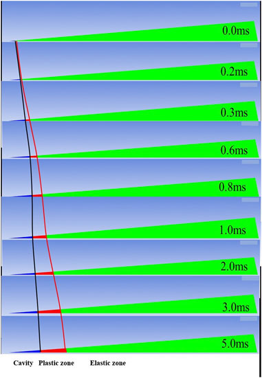
FIGURE 5. Movement of the explosion-damaged area.
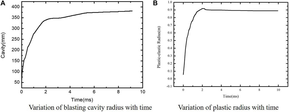
FIGURE 6. Time-dependent movement of the boundary of different blasting areas.
In Figure 6A, the blasting cavity radius is formed after the dynamite blast increases with time, and the size of the blasting cavity gradually tends to a certain value near the position of 2 ms. The region of the explosion cavity in this method is 0.36 m (Chenglong and Wang, 2017), and the region which is calculated by a quasi-static model is 0.37 m. The regions we obtained through experiments are 0.38 m (Chenglong and Wang, 2017). In Figure 6B, it is obvious that the plastic range formed after the dynamite blast begins to develop almost at the same time as the cavity and expands outward at the same time. When the pressure reaches the limit of yielding of geomaterials, the plastic range stops developing and approaches a certain value, which is the elastoplastic boundary after the final stabilization.
The initial pressure load generated by the explosion (Figure 7) and the pressure load on the elastoplastic boundary (Figure 8) are extracted, respectively. It can be seen from the change in the pressure load that the peak value of the pressure load drops rapidly from 3 GPa to 2.5 MPa, and the duration also increases from 0.02 ms to 2 ms.
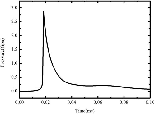
FIGURE 7. Initial pressure elastic–plastic boundary.
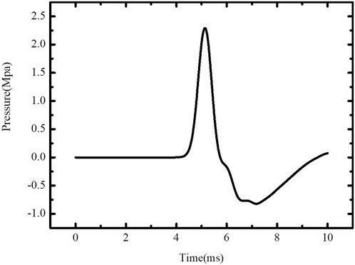
FIGURE 8. Pressure on the elastic plastic boundary.
4 Propagation model of explosive seismic waves
The Lagrange model is adopted to simulate the propagation of the initial elastic wave in geomaterials. Since the pressure peak of the initial elastic wave is basically consistent with the yield condition of the geomaterial, under the loading condition of the initial elastic wave, the medium will not experience large deformation. By changing the load of the initial elastic wave, the whole process of the seismic wave field excited by the explosive source is simulated.
4.1 Control equations
When the initial elastic wave is formed, its pressure peak is less than the limit of yielding of the medium. Hence, it will not cause large deformation in the geomaterial. In this regard, the Lagrange method is applied to simulate the propagation process of seismic waves, and the governing equations include the mass-conservation equation, the momentum-conservation equation, and the energy-conservation equation in the following form.
Mass-conservation equation:
Momentum-conservation equation:
Energy-conservation equation:
4.2 Physical model
By simulating the formation of the blasting seismic wave, the radius of the elastoplastic boundary and the pressure curve on the elastoplastic boundary are obtained. When the curve is applied to the viscoelastic medium models in the initial condition, the propagation process of seismic waves can be simulated.
For the geomaterial in the propagation process of the seismic wave, the viscoelastic medium model is adopted, in which the linear equation of state is selected. The linear viscoelastic model is adopted for the intensity model of geomaterials. The long-term behavior of this model is described by the elastic shear modulus G, and the viscoelastic behavior is introduced by the instantaneous shear modulus (G0) and the viscoelastic attenuation constant (β). The viscoelastic deviatoric stress at the time increment n + 1 is calculated from the viscoelastic stress at the time increment n and is expressed as follows (Ricker, 1953):
For the effect of the explosive source, we extract the data curve of the blasting seismic wave formation simulation in the previous step and load the corresponding explosive source.
4.3 Geometric model
The calculation model is shown in Figure 9.

FIGURE 9. Calculation model diagram.
The observation points (Gaussian point) are set at the free surface of the geomaterial and below the explosive source, with a burial depth of explosives of 15 m as measured by the observation points. The variation of the seismic wave excited by the explosive source on the surface and the downward direction is analyzed. The overall computational domain is 200 m × 100 m, and the free boundary is selected on the surface of the soil medium, while the transmitting boundary is adopted for other boundaries. These boundary conditions do not reflect the stress wave propagating along these boundaries.
4.4 Calculation results
We simulated the aforementioned case using a dual-core CPU (Intel Xeon Silver 4210 R Processor) and calculated each scenario for 10 h, resulting in the following results. By simulating the propagation process of the seismic wave, Figure 10 reveals the vibration velocity nephogram of seismic waves excited by 1 kg TNT at 10 ms, 30 ms, and 50 ms. Qualitative analysis is adopted on the nephogram of different particle vibration velocities. At 10 ms, the seismic wave excited by the explosive takes the explosive source as its center and radiates spherical stress waves to the surrounding area. As the stress wave propagates, stress waves with different peaks are gradually formed in the medium. It is easily seen from the velocity contours of 30 ms and 50 ms that although the detonation products of the explosive source have already been completed at this time, the particle velocity of the explosion center is higher than the external vibration velocity, indicating that the blasting cavity generated by the explosive source is still moving after the explosion. This is the main cause of the subsequent seismic wave, which is the same as Ding Hua’s conclusion that the seismic wave signal is due to the cavity vibration.
FIGURE 10. Seismic wave velocity nephogram at different times.
The results of the particle velocity at 30 m from the explosion center are shown in Figure 11, and by Fourier analysis on the vibration velocity, we obtained Figure 12:
FIGURE 11. Comparison of particle vibration velocities obtained by numerical simulation.
FIGURE 12. Spectrum features of particle vibration.
Through the numerical simulation of the explosive source excitation seismic wave process, the explosive cavity, plastic range, particle velocity, and spectrum features at different distances can be obtained. As a result, the relation between parameters of explosive-source characteristics and amplitude-frequency characteristics of the seismic wave field can be deeply analyzed.
5 Influence of parameters of explosive source characteristics on amplitude frequency characteristics of seismic waves
Through the theoretical study on seismic waves stimulated by explosive sources, when the geotechnical medium parameters are determined, the detonation pressure of explosive sources and the expansion index of explosion products are the main factors that affect the amplitude frequency characteristics of seismic waves. The following are respective studies on the patterns of how different detonation pressures and product expansion indexes affect the amplitude frequency characteristics of seismic waves.
We continue to use the numeric simulation scheme propagated by blasting seismic waves as described previously to change the bursting pressure of explosive sources so that the detonation pressure can vary in the range of 5–25 GPa. A monitoring point on the surface directly above the explosive source is selected 15 m away from the explosive source, and the particle velocity caused by different detonation pressures at this point is shown in Figure 13.
FIGURE 13. Particle velocity at 15 m from the explosion center at different distances of explosion pressure.
By extracting the particle vibration velocity peak under different detonation pressures, the influence law of the detonation pressure on the particle vibration velocity peak is obtained, as shown in Figure 14A; PPV in this figure is the peak particle velocity. Through Fourier transform on the velocity curve in Figure 13, the influence law of the detonation pressure on the dominant frequency of the seismic wave is acquired, as shown in Figure 14B:
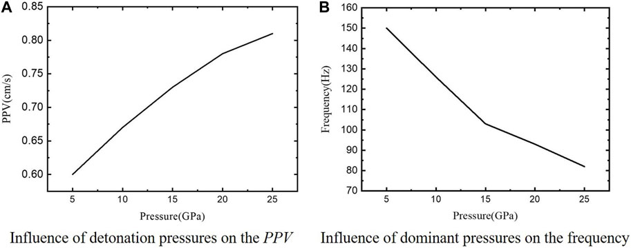
FIGURE 14. The influence law of seismic wave field characteristics under different detonation pressures.
Figure 14 proves that the particle vibration velocity peak value increases with the increase in the detonation pressure. Both the particle vibration velocity peak value and the particle vibration amplitude are parameters representing the seismic wave energy. The law of energy increasing with the increase in the bursting pressure obtained by the numerical method is consistent with the conclusion of the theoretical model of the seismic wave by the explosive source. The increase in the explosive pressure leads to the expansion of the damage area by the media and more loss on high-frequency parts, lowering the master frequency of seismic waves. The detonation pressure of the explosive source in the numerical simulation scheme remains unchanged, and the expansion index of the explosion products of the explosive source varies from 1.0 to 4.0. Then, the calculated attenuation law is obtained as shown in Figure 15:
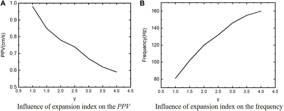
FIGURE 15. Influence of the expansion index of different explosion products on the characteristics of seismic wave field.
Figure 15 shows that the particle vibration velocity peak decreases with the expansion index of detonation products, and the dominant frequency of the seismic wave increases with the increase in the product expansion index. The process of explosive source exploding and forming a damage area is very fast, which is considered as an adiabatic process. According to the adiabatic law, when the product expansion index increases, the damage area decreases by explosion, the energy decreases, but the main frequency increases.
6 Conclusion
Based on the numerical simulation of the characteristics of the explosive source and the relation of the wave field, the development process of the explosive cavity and elastic–plastic boundary is collected along with the variation rule of seismic wave amplitude frequency characteristics with distance.
The formation of seismic waves is simulated by the Eulerian method. During the formation of seismic waves, along with the development of explosive cavities and elastoplastic range, the boundaries between the three zones almost expand simultaneously along the explosion center until the explosive cavity, plastic range, and elastic zone are formed in turn.
The Lagrange method is applied to simulate the propagation process of seismic waves, extract the numerical simulation data curve of the formation process of seismic waves, and load it into the two-dimensional Lagrange model. The vibration velocity of the particles at different positions can be acquired, and the Fourier transform can be adopted to obtain the spectral features of the particle vibration.
Finally, the influence law of the explosive source detonation pressure and the expansion index of explosion products on the particle vibration velocity peak and the dominant frequency of the seismic wave are analyzed. The detonation pressure and expansion index of explosive sources exert opposite effects on the energy and dominant frequency of seismic waves, and the change law between the energy of the seismic wave and the master frequency is often the opposite, and this conclusion was calculated by our prediction model for amplitude–frequency characteristics of blast-induced seismic waves (Chenglong et al., 2018). While the energy of the seismic wave increases, the master frequency of the seismic wave decreases. To finally realize the control of the seismic wave field and improve the seismic exploration accuracy, it is vital to comprehensively consider the influence law of the explosion pressure of the blasting source and product expansion index on the amplitude and frequency of seismic waves and adjust the amplitude and frequency characteristics of seismic waves to a certain extent, so as to improve the seismic exploration accuracy.
Data availability statement
The raw data supporting the conclusion of this article will be made available by the authors, without undue reservation.
Author contributions
CY finished writing the manuscript. XS completed the numerical calculation. QG completed the data processing. XZ completed the translation of the thesis. FW completed the typesetting and modification of the paper. All authors listed made a substantial, direct, and intellectual contribution to the work and approved it for publication.
Funding
This work was supported by the National Natural Science Foundation Young Investigator Grant Program (No. 41904131).
Conflict of interest
FW was employed by the company Shanxi Transportation Technology Research and Development Co., Ltd.
The remaining authors declare that the research was conducted in the absence of any commercial or financial relationships that could be construed as a potential conflict of interest.
Publisher’s note
All claims expressed in this article are solely those of the authors and do not necessarily represent those of their affiliated organizations, or those of the publisher, the editors, and the reviewers. Any product that may be evaluated in this article, or claim that may be made by its manufacturer, is not guaranteed or endorsed by the publisher.
References
Aboudi, J. (1972). The response of an elastic half-space to the dynamic expansion of an embedded spherical cavity. Bull. Seismol. Soc. Am. 62 (1), 115–127. doi:10.1785/BSSA0620010115
Achenbach, J. D., and Sun, C. T. (1966). Propagation of waves from a spherical surface of time-dependent radius. J. Acoust. Soc. Am. 40 (4), 877–882. doi:10.1121/1.1910160
Blair, D. P. (2007). A Comparison of heelan and exact solutions for seismic radiation from a short cylindrical charge. GEOPHYSICS 72 (2), E33–E41. doi:10.1190/1.2424543
Blair, D. P. (2010). Seismic radiation from an explosive column. Geophysics 75 (1), E55–E65. doi:10.1190/1.3294860
Blake, F. G. (1952). Spherical wave propagation in solid media. J. Acoust. Soc. Am. 24 (2), 211–215. doi:10.1121/1.1906882
Bycroft, G. N. (1966). Surface displacements due to an underground explosion. Bull. Seismol. Soc. Am. 56 (4), 877–888. doi:10.1785/bssa0560040877
Chenglong, Y., and Wang, Z. (2017). Quasi-static model for predicting explosion cavity with spherical charges. Explos. Shock Waves (02), 249–254.
Chenglong, Y., Zhongqi, W., and Wengong, H. (2018). A prediction model for amplitude-frequency characteristics of blast-induced seismic waves. Geophysics 83 (3), 5MJ–Z13. doi:10.1190/geo2017-0228.1
Chenglong, Y., Zhongqi, W., and Wengong, H. (2017). A prediction model for frequency spectrum of blast-induced seismic wave in viscoelastic medium. Geophys. Prospect. 66 (S1), 87–98. doi:10.1111/1365-2478.12601
Ding, H., and Zheng, Z. M. (2002). Source model for blasting vibration. Sci. China (Series E:Technological Sci. (4), 395–407. doi:10.1360/02ye9046
Drukovanyi, M. F., Kravtov, V. S., Chernyavskii, Y. E., Shelenok, V. V., Reva, N. P., and Zver'kov, S. N. (1976). Calculation of fracture zones created by exploding cylindrical charges in ledge rocks. Soviet Min. Sci. 12 (3), 292–295. doi:10.1007/bf02594873
Favreau, R. F. (1969). Generation of strain waves in rock by an explosion in a spherical cavity. J. Geophys. Res. 74 (17), 4267–4280. doi:10.1029/jb074i017p04267
Forrestal, M. J., and Tzou, D. Y. (1997). A spherical cavity-expansion penetration model for concrete targets. Int. L Solids Struct. 34 (31-32), 4127–4146. Nos. doi:10.1016/s0020-7683(97)00017-6
Friedman, M. B., Bleich, H. H., and Parnes, R. (1965). Spherical elastic plastic shock propagation. J. Eng. Mech. Div. 91 (3), 189–203. doi:10.1061/jmcea3.0000623
Garg, S. K. (1968). Numerical solutions for spherical elastic-plastic wave propagation. Z. fur Angew. Math. Phys. (ZAMP) 19 (5), 778–787. doi:10.1007/bf01591008
Garg, S. K. (1968). Spherical elastic-plastic waves. Z. fur Angew. Math. Phys. 19 (2), 243–251. doi:10.1007/bf01601469
Ghosh, M. L. (1968). On the propagation of spherical waves due to large underground explosion. Pure Appl. Geophys. 72 (1), 22–34. doi:10.1007/bf00875689
Goldsmith, W., and Allen, W. A. (1955). Graphical representation of the spherical propagation of explosive pulses in elastic media. J. Acoust. Soc. Am. 27 (1), 47–55. doi:10.1121/1.1907495
Heelan, P. A. (1953). Radiation from a cylindrical source of finite length. Geophysics 18 (8), 685–696. doi:10.1190/1.1437923
Henrych, J. (1979). The dynamics of explosion and its use. Amsterdam, Netherlands: Elsevier Scientific Publishing Company.
Jeffreys, H. (1931). On the cause of oscillatory movement in seismograms. Roy. Astr. Soc. Geophys.suppl. 2 (2), 407–416. doi:10.1111/j.1365-246x.1931.tb04462.x
Kawasumi, H., and Yosiyama, R. (1935). On an elastic wave animated by potential energy of initial strain. Bull. Earthq. Res. Inst. Tokyo Imp. Univ. 13, 496–503. doi:10.3390/computation11020015
Lyakhov, G. M. (1964). Principles of explosion dynamics in soils and in liquid media. Москва, Russia: Недра.
LyakhovPolyakova, G. M. N. (1967). Waves in compact media and loading of structures. Москва, Russia: Недра.
Pekeris, C. L. (1955). The seismic surface pulse. Proc. Nat. Acad. Sei. U.S.A. 41, 469–480. doi:10.1073/pnas.41.7.469
Ricker, N. (1953). The form and law of propagation of seismic wavelets. Geophysics 18, 10–40. List of symbols. doi:10.1190/1.1437843
Sharpe, J. A. (1942). The production of elastic waves by explosion pressures. Geophysics 7 (7), 311–321. doi:10.1190/1.1445016
Thiruvenkatachar, V. R., and Viswanathan, K. (1967). Dynamic response of an elastic half-space to time-dependent surface tractions over an embedded spherical cavity. Proc. Roy. Soc. Lond. A 300, 159–186. doi:10.1098/rspa.1965.0196
Thiruvenkatachar, V. R., and Viswanathan, K. (1965). Dynamic response of an elastic half-space to time-dependent surface tractions over an embedded spherical cavity. Proc. Roy. Soc. Lond. A 287, 549–567. doi:10.1098/rspa.1965.0196
Yixin, Z., Chunhua, B., Chen, J., and Zhongqi, W. (2013). Simulations of seismic waves stimulated by aluminized explosive. Chin. J. High Press. Phys. 027 (006), 872–876.
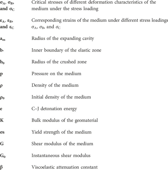
Nomenclature
List of symbols
<
Keywords: explosive source, seismic wave, numerical model, seismic exploration, transformation mechanism
Citation: Yu C, Shi X, Gao Q, Zhang X and Wang F (2023) Research on the evolution law of the seismic wave field based on the explosive source parameters. Front. Earth Sci. 11:1189129. doi: 10.3389/feart.2023.1189129
Received: 18 March 2023; Accepted: 09 May 2023;
Published: 14 June 2023.
Edited by:
Jingjing Meng, Luleå University of Technology, SwedenReviewed by:
Gang Huang, Wuchang University of Technology, ChinaXu Qian, Changzhou University, China
Copyright © 2023 Yu, Shi, Gao, Zhang and Wang. This is an open-access article distributed under the terms of the Creative Commons Attribution License (CC BY). The use, distribution or reproduction in other forums is permitted, provided the original author(s) and the copyright owner(s) are credited and that the original publication in this journal is cited, in accordance with accepted academic practice. No use, distribution or reproduction is permitted which does not comply with these terms.
*Correspondence: Chenglong Yu, eWNsMTk4ODAyMjhAMTI2LmNvbQ==