 Dechao Zhang
 Haicheng She*
- School of Urban Construction, Yangtze University, Jingzhou, Hubei, China
The influence of fissure angles and bridge lengths on rock mechanical properties and failure was analyzed using the uniaxial compression test and the Digital Image Correlation (DIC) technique. The research findings are as follows: 1) Peak stress and elastic modulus of the samples exhibited an obvious change trend with the change in fissure angle. The fissure angle has a more significant effect on a rock’s mechanical properties than the length of the rock bridge. 2) With an increase in the fissure angle, the number of surface cracks, main failure cracks and surface spalling decreased, whereas the area of the falling blocks significantly increased. However, with an increase in bridge length, the characteristics of crack propagation and spalling are essentially the same. During crack propagation, the connection of the rock bridge is related to its fissure angle and length. 3) At a low fissure angle, the failure mode of rock samples is dominated by tensile-failure cracks; with an increase in fissure angle, the tension-damage to shear-damage crack transformation will form a mixed tensile-shear damage mode; at the same time, with an increase in bridge length, the rock bridge becomes more difficult to connect, and the local crack expansion failure changes from tensile-shear cracks to tensile cracks. 4) Stress on the coplanar double-fissured rock sample was simplified and analyzed to explain the behavior of fractures on the sample. These research results have an important guiding value for engineering optimal designs.
Highlights
1. The influence of bridge length on mechanical properties was weaker than that of the fissure angles’ influence.
2. With the increase of the fissure angle, the failure mode changes from tension to shear.
3. The increase of the length of the rock bridge affects its connection.
4. The bridge connection occurs only at a high fissure angle.
5. The failure behavior was affected by the normal stress double-clamped beam model and shear stress.
1 Introduction
The fissured rock mass is a common engineering medium in water conservancy and hydropower projects. Such fissure defects not only impact the mechanical properties of rock masses, but also increase the risk of engineering accidents, since more cracks may sprout and expand from internal cracks upon experiencing external disturbance (Lajtai et al., 1990; Hoek and Martin., 2014; He et al., 2022; Wong et al., 2022; Ren et al., 2023). It is therefore of great theoretical significance to investigate the influence of the geometric distribution of cracks on rock mass mechanical properties, crack propagation, and damage of rock masses. Lajtai (1969) believed that simulating real rock by using rock-like material to precast fissures, thus greatly simplifying sample preparation, was feasible; this is now widely accepted. Since then, Park and Bobet (2009) (Wong and Einstein., 2009; Yang and Jing., 2011) assigned a uniform name to the precast fissure. The terms “fissure” or “flaw” are used to describe a man-made pre-existing crack or fracture. In addition, the names of the cracks caused by the load in the rock samples are unified. Wing crack, anti-wing crack and secondary crack are unified Bobet (2000) determined the tensile and shear properties of the wing and secondary cracks. Previous studies mostly focused on Intact rock sample (Liang et al., 2022; Tang et al., 2022) and single-fracture rock samples (Wong and Einstein, 2009; Yang, 2011; Liang et al., 2012; Xiao et al., 2012; Xu et al., 2013; Jin et al., 2017), while current research on fissured rock masses has developed towards multiple fissure; many achievements have been made in double-fissured rock mass research. Zhang et al. (2006) conducted uniaxial compression tests on 45°, 55°, 65° coplanar double fissured sandstone specimens and observed that the secondary coplanar crack is easy to occur in the inner end of coplanar double fissure, forming coplanar shear through. Yang and Jing. (2011) studied coplanar double fissures with different dip angles and found that the degree of peak strength reduction in fissure samples was related to coplanar double fissures, ultimate failure modes are obviously dependent to coplanar fissure angle. Sun et al. (2018) conducted uniaxial compression tests on rock samples with different dip angles, fissure forms, and rock bridge spacings and discovered that peak strength showed a downward concave trend with increasing fissure dip angle; the smaller the rock bridge distance, the easier it is to connect and the smaller the peak strength. The length of coplanar double-fissure rock bridge becomes longer, and wing cracks and anti-wing cracks are easy to occur at the fissure tip. Wasantha et al. (2012) used cement mortar to make single-fissure cylindrical specimens with different angles and fissure lengths and studied the effects of fissure length and angle on the mechanical properties and fracture modes of the specimens under uniaxial compression. Specimens with longer partially-spanning joints, failure was seeded at the pre-existing fissure tip, whereas for specimens with shorter partially-spanning joints, failure was not associated with the pre-existing fissure. Xiao et al. (2015) conducted triaxial compression tests on two parallel fissured cylindrical rock samples and observed that when the fissures are arranged in coplane, the failure mode is X-type shear failure formed by coplane propagation crack and anti-wing crack. In the non-superimposed arrangement, the failure modes range from tensile shear failure at medium and low confining pressures to anti-wing crack penetration failure at high confining pressures. Yang et al. (2022) used a conventional triaxial compression test to study granite samples with two non-coplanar open fissures, and defined five modes of crack penetration. The results from Yang et al. (2022)’s investigation show that, under uniaxial and low confining pressure conditions, the rock bridge angle has a significant influence on the crack evolution behavior. However, under high confining pressure, with the propagation of the anti-wing crack, a shear will lead to final failure. Yin et al. (2014) studied the bonding mechanism between surface cracks of two parallel fissures in granite samples under uniaxial compression and found that the anti-wing crack initiation process is tensile, and the penetration of the precast fissure occurs on both the surface and internally. Wang et al. (2018) conducted a biaxial test on prefabricated double-fissure rock samples and divided the rock bridge connection into three categories: the influence of lateral stress caused by the original fissure angle, rock bridge angle, and crack propagation in the coalescence mode. Cao et al. (2015) produced rock samples with two and three fissures and analyzed the effect of prefabricated fissures on the crack formation process. Wang et al. (2018) studied rock samples with parallel-fissure clusters and obtained four damage modes for jointed rock samples under compression-shear loading; dip angle had a significant effect on the damage mode. With increasing fissure angle, the coalescence mode changes from the propagation of two wing cracks that coalesces to form a single wing crack coalescence mode. Research on cracks has become more increasingly complicated, including fissure groups (Prudencio and Van., 2007; Wang et al., 2018; Zhang et al., 2020), fissures in the form of pores (Zhang et al., 2006; Pu et al., 2010; Zhao et al., 2013; Chen et al., 2017; Yang et al., 2017; Gong et al., 2020), and non-parallel irregular cracks (Park and Bobet, 2010; Janeiro and Einstein, 2010; Yang et al., 2013; Cao et al., 2015). Although the fissure tendency is complicated, the core of the research is always the influence of defects on the specimen and the form and propagation of the cracks generated by loading.
Many studies on double fissures have primarily focused on parallel fissures, and mainly on the fissure and rock bridge dip angles on rock damage mode, crack extension, and rock bridge penetration. Conversely, fewer studies address coplanar double fissures and the length of the rock bridge between two fissures. At the same time, study of rock sample failure tends to focus on the final failure mode, lacking the summary of the law of rock sample failure characteristics and failure mechanism in the whole loading process. Therefore, this study considers sandstone specimens of the special coplanar double fissures in parallel cracks as the research objective to explore the influence of different coplanar double fissures angle and bridge length on the mechanical properties and failure characteristics of sandstone. In addition, this paper summarizes the fracture mechanics model, explains the fracture behavior of each rock sample and reveals the failure mechanism of rock sample.
2 Test apparatus and test program design
The main instrument consisted of a loading system and a DIC system, as shown in Figure 1. Figure 2 shows the physical picture of the instrument; the loading system included WAW-1000B Microcomputer Servo-controlled Universal Testing Machine and data acquisition system, and the DIC system included both a shooting system and a digital image calculation system with a maximum load of 1,000 kN. The loading system not only controlled the force or displacement of the sample, but also conducted uniaxial compression, tensile and cyclic loading, and creep tests. The loading system adopted a displacement control, and the displacement loading rate was 0.2 mm/min. The DIC system was comprised of non-contact, optical, and three-dimensional measurement equipment for material displacement, strain measurement, and analysis. The system was primarily composed of a computer control system (DIC software, control box), a support system (tripod, platform, beam), and a measurement system (camera and light source). Double cameras at both ends of the beam were used for monitoring. The resolution, frame rate, lens focal length, light-source focal length, and pixel size were 4096 px × 3000 px, 30 fps, 12 mm, 10 mm, and 3.45 μm, respectively.
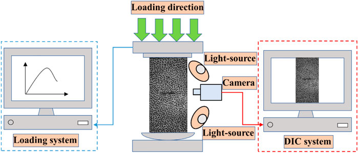
FIGURE 1. Schematic diagram of the test system.
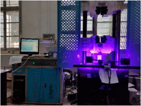
FIGURE 2. Test instrument physical picture.
Owing to the difficulty of sampling in the field to obtain coplanar double-fissured sandstone specimens of similar size, the required samples needed to be made manually. In recent years, laboratory simulation tests with similar materials have been applied to jointed fissured and layered rock masses. Many scholars have developed rock-like materials and have achieved substantial results.
The mass ratio of the rock sample was 32.5R ordinary silicate cement: quartz sand: pure water: polycarboxylate acid early strength water reducing agent: defoamer = 1:1:0.28:0.002:0.003. A cuboid mold with dimensions of 70 mm × 70 mm × 143 mm was adopted, as shown in Figure 3, and the steel sheet was pre-inserted into the mold before pouring. After the initial setting, the steel sheet was removed, creating a perforating crack without filling.
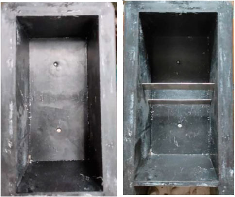
FIGURE 3. Mold diagram.
The schematic diagram of the fissure distribution of the rock sample is shown in Figure 4 below. In Figure 4B, a is the fissure length, mm; 2b is the rock bridge length, mm; α is the fissure dip angle, (°); β is the rock bridge dip angle, (°); and α = β. In the uniaxial compression test, the WAW-1000B was used for loading at a rate of 0.2 mm/min. The whole process of rock surface crack evolution was monitored by the DIC system; the camera frame rate was 1 frame/s.
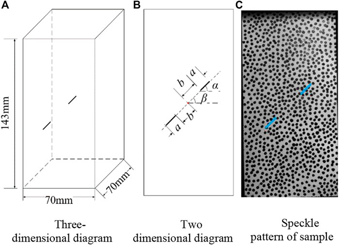
FIGURE 4. Distribution diagram of coplanar double fissures. (A) Three-dimensional diagram; (B) Two dimensional diagram; (C) Speckle pattern of sample.
To investigate the effects of the fissure angle and rock bridge length on the mechanical strength properties and damage mode of coplanar double-fissured sandstone, the two fissure lengths (a) prefabricated in the rock samples were 10 mm, and the fissure thickness was 0.5 mm. The fissure dip angles (a) were taken as 0°, 30°, 45°, 60°, and 90°, and the rock bridge lengths (2b) were taken as 7 mm, 14 mm, 21 mm, and 28 mm. The rock sample numbers were named in α-2b format, and the test protocol and specimen numbers are listed in Table 1.
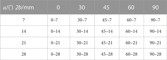
TABLE 1. Test plan and specimens’ number.
3 Test results and analysis
3.1 Effects of fissure dip angle and rock bridge length on the mechanical properties of rock samples
Uniaxial compression tests were performed on each rock sample according to the test scheme presented in Table 1, and the stress-strain curves of the rock samples were obtained, as seen in Figure 5.
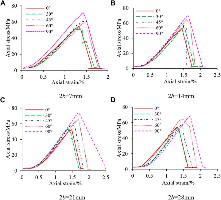
FIGURE 5. Axial stress-strain curve of rock specimens with different fissured angles. (A) 2b = 7 mm; (B) 2b = 14 mm; (C) 2b = 21 mm; (D) 2b = 28 mm.
As shown in Figure 5, the stress-strain curve obtained from the test contains three stages: compression-density, elastic, and yield. There is no obvious plastic deformation before the peak stress of the stress-strain curve, where a long elastic stage is seen, indicating that the rock sample has a strong brittle characteristic. There is a slight stress drop appearing in the stage before reaching peak stress, that is, a sudden change in slope, which indicates that new cracks sprouted in-between prefabricated fissures within the rock sample. Statistical analysis of the test data shows that the peak stress and elastic modulus of each rock sample vary with the fissure angle and length of the rock bridge, as shown in Figures 6, 7.
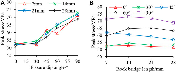
FIGURE 6. The variation of peak stress with fissured angles and rock bridge lengths. (A) Fissure dip angle VS. Peak stress; (B) Rock bridge length VS. Peak stress.
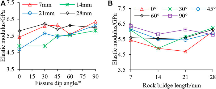
FIGURE 7. The variation of elasticity modulus with fissured angles and rock bridge lengths. (A) Fissure dip angle VS. Elastic modulus; (B) Rock bridge length VS. Elastic modulus.
From Figure 6A, it can be seen that the peak stress tends to increase significantly with the increase of fissure angle at the same rock bridge length. When α = 0°, the peak stress of the rock sample is between 51.5 and 53.1 MPa, which is a serious weakening of the rock sample’s mechanical strength when compared with 74.0 MPa of the intact rock sample, with a weakening degree of 30.4%–28.2%. When α = 90°, the peak stress of the rock sample is between 68.7 and 73.0 MPa, with a weakening degree of 7.3%–1.3%, which is very close to the strength of the intact rock sample. From Figure 6B, it is observed that under the same fissure angle, peak stress increases with the length of the rock bridge, and its value is more similar in magnitude. Demonstrating the law of increasing first and then decreasing or decreasing in a small way. Overall variation range of peak stress is small, and the difference between the maximum and minimum value of peak stress of rock samples with different bridge lengths is between 1.5 and 5.7 MPa under five fissure angles. Bridge length has little influence on the peak strength of rock samples. As can be seen from Figure 7, the elastic modulus of the rock sample displays an increasing trend with the increase in the fissure angle, but the growth rate varies widely, with a maximum growth rate of 30.4% and a minimum growth rate of 3.4%. The elastic modulus of the rock sample shows a concave trend of decreasing and then increasing, with an increase in bridge length, and an elastic modulus change rate of between −8.8% and 10.5%. In summary, coplanar double-fissure specimen mechanical properties increase with an increase in fissure angle, and the influence of rock bridge length on the mechanical properties of rock samples is small, and the degree of influence on the mechanical properties of rock samples is weaker than fissure angle.
3.2 Influence of fissure dip angle and bridge length on the damage characteristics of rock samples
In the uniaxial compression test, the strain cloud map generated by the DIC system was used to assist in the analysis of the crack expansion process on the surface of the rock samples. The sequence of crack generation at different stress levels in rock samples was captured by the camera, as displayed by specimens 0–14 in Figure 8. Crack generation speed is extremely high. The moment when a large number of cracks suddenly occur is defined as a batch of crack generation. Numbers ①, ②, ③, and ④ in the figures represent successive batches of cracks generated at different stress levels. The main rupture crack at the time of damage is indicated by a solid black thick line. Surface spalling is indicated by the gray variegated color in the interior of the rock sample; simultaneous spalling blocks are indicated in black.
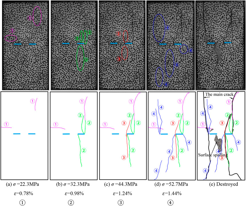
FIGURE 8. Crack propagation and failure of rock samples with α = 0° and 2b = 14 mm.
The surface crack propagation law of the rock sample is as follows: at low-stress levels, as seen in Figure 8A, ① appeared near the upper face and left edge of the rock sample, and belonged to far-field cracks, which are caused by uneven upper and lower end faces of the rock sample, or uneven force on the end faces. At medium stress levels, cracks appeared at the tips of the precast fissures and expanded towards the ends of the rock sample. In Figures 8B, C, ② is a wing crack and ③ possesses both a wing crack and an anti-wing crack. In both Figures, ② and ③ are fused with the ① far-field cracks. They are mainly concentrated at both ends of the right prefabricated fissure, which indicates that the force on the end face is not uniform. At high-stress levels, cracks occurred at the two prefabricated fissure tips, rapidly propagated to the end of the rock sample, and integrated with other batches of cracks, forming an obvious main failure crack composed of wing cracks and anti-wing cracks, as well as spalling off the falling block. As shown in Figures 8D, E failure diagram, ④ were still mainly wing cracks and anti-wing cracks. At this point, the stress dropped abruptly, damaging the rock sample.
By combining the cracks of each batch marked in the rock sample failure diagram with the stress-strain curve of the rock sample failure process, owing to small stress that does not reach the crack initiation levels in the compression-density stage. The cracks in batches ① and ② appear in the elastic stage as the stress increases. When the yield damage stage, the stage where most cracks are produced, is reached, the cracks expand rapidly to form ③, ④, ultimately reaching peak strength and destroying the rock sample. From the damage diagram of each rock sample, the ① and ② batches of cracks are identified as the far-field cracks near the end, as well as the wing cracks at the tip of the crack. The ③ and ④ batches are easily identified as: the new cracks expanding onto the path of ① and ②, the far-field cracks that further break the rock sample, the wing cracks at the tip of the fissure, and the tensile cracks in the middle of the fissure. However, batches ③ and ④ were not all formed by the deepening of the crack growth caused by batches ① and ②. With the increase in stress level, cracks generated by batches ① and ② continued to expand, and new cracks were simultaneously generated. The new crack expansion caused the crack closure phenomenon in the original ① and ② batches. As shown in Figure 9, the crack closure of batch ② was caused by the crack expansion of batch ③ in rock samples 0–7, but the closure of the crack did not affect the development of the main crack at the failure stage of the rock samples. The closed crack in the failure diagram of rock samples 0–7 eventually forms the main fracture crack. Meanwhile, the formation and development of the main cracks were not determined by the batch of cracks.
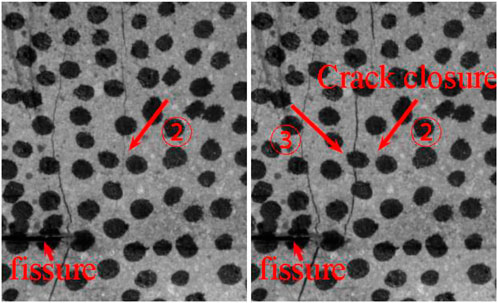
FIGURE 9. Crack closure.
Besides illustrating the law of crack propagation with stress increase, the failure diagram can also reveal the failure characteristics of rock samples. Therefore, the failure diagram is used below to explore the failure characteristics of rock samples with the angle of fissure and the length of the rock bridge, as shown in Figure 10.
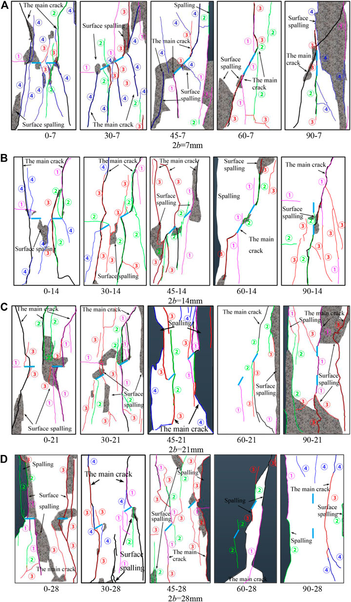
FIGURE 10. Crack propagation and failure diagram of various rock samples. (A) 2b = 7 mm; (B) 2b = 14 mm; (C) 2b = 21 mm; (D) 2b = 28 mm.
As can be seen from Figure 10, 1) with the influence of fissure angle on the damage characteristics of rock samples, and under the same rock bridge length combined with an increase in fissure angle, i) the number of cracks trended towards being significantly reduced, and the number of main damage cracks changed from two to one, thus indicating that the damage mode of the specimen has changed from tension damage to shear damage; ii) surface spalling usually occurs where the crack manifests, which is a sign of large deformation and a large number of cracks. With an increase in the fissure angle, the number of surface spalling dropped blocks decreased, and the area of the falling blocks increased significantly. This is because under a high fissure angle, the number of cracks on the sample surface is small, and the block area formed between cracks or surrounded by the sample edge is large; thus, the area of the falling blocks is large. Figure 6 also shows that the number of cracks decreased and the failure mode changed from tensile failure to shear failure. Some rock samples exhibited severe failure, with rock blocks collapsing and spalling along the cracks. This phenomenon occurred mostly on both sides of the rock samples, which is a manifestation of the severe energy dissipation of the rock samples. iii) Whether the rock bridge is connected is shown as follows. First, three rock bridge connecting modes are defined, as shown in Table 2. When the fissure angle was low (α = 0° and α = 30°), rock bridge penetration did not occur. When the fissure angle was high (α = 45°, 60°, and 90°), rock bridge penetration occurred. 2) The influence of bridge length on the damage characteristics of rock samples: Under the same fissure angle, with the increase in rock bridge length, i) damage characteristics, such as a crack extension or spalling block on the surface of rock samples, are the same. ii) the longer the bridge, the more difficult it is to connect at the fissure dip angle. 3) From the point of view of the fine damage mechanism, i) at a low fissure angle (α = 0° or 30°), the cracks produced on the surface of the rock sample are mainly tension cracks; there are few shear cracks. At a low fissure dip angle, a large shear stress cannot be formed locally, and the stress concentration at the fissure tip instead forms a local tension stress, which causes tension cracks and expands in the direction of maximum principal stress, extending from the tip to the end of the sample, and forming a “butterfly shape” failure of two main cracks on its surface; the failure mode is similar with the change of rock bridge length. ii) When α = 45° and α = 60°, and the length of the rock bridge is relatively small, the rock bridge is connected, forming an elongated shear zone, increasing the proportion of shear damage of the specimen. The cracks generated on the surface are mixed shear and tension cracks, which manifest as a mixed tension-shear failure, causing the surface of the specimen to form a main rupture crack of “single-wing butterfly”-like damage. When α = 60°, the shear stress was larger because this angle was closer to the fracture surface 45°+
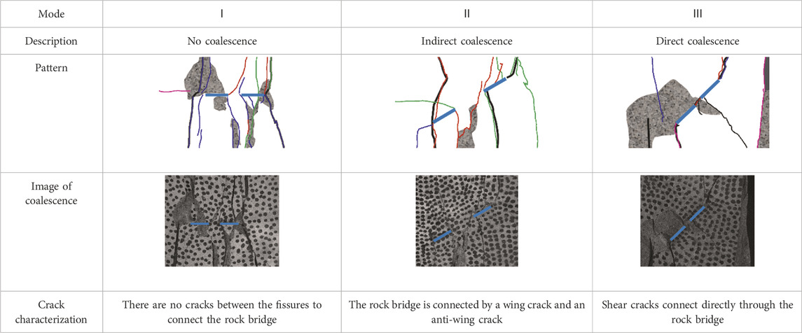
TABLE 2. Three kinds of rock bridges through modes of coplanar double-fissured sandstones.
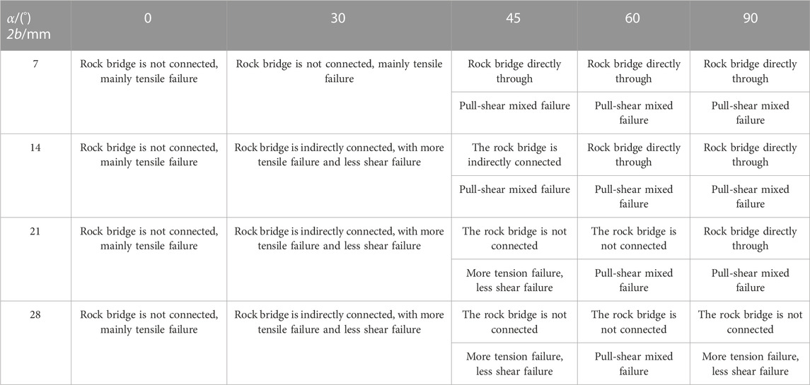
TABLE 3. Failure characteristics and mechanism of rock samples.
As can be seen from Table 3, the fissure angle and length of the rock bridge jointly affect the rock bridge connection and failure mode of the rock samples. The bridge connection occurred only at a high fissure angle. With an increase in the fissure angle, when the rock sample failed, the rock bridge between the two prefabricated fissures changed from disconnected to indirectly connected, and then directly connected, further indicating that the failure mechanism of the rock sample has changed from tension crack to tension-shear crack. The length of the rock bridge is directly proportional to the difficulty of connecting the rock bridge. As the length increases, the rock bridge between two prefabricated fissures becomes increasingly difficult to connect, especially when α = 45°, 60°, and 90°, and the rock bridge changes from directly connected to indirectly connected or completely disconnected. This change also indicates that the failure mechanism of the rock sample changes from tension-shear mixed cracks to tensile cracks. This observation is consistent with the mechanical properties of the rock samples.
The effect of the fissure angle on the mechanical properties of rock samples with double fissures is similar to that of single fissures, but there are differences in the crack growth and failure modes. When fissure lengths are the same, the two fissures indicate that the proportion of defects is larger. Furthermore, whether the rock bridge is connected or not changes the failure mode of the sample between tensile or shear. Conversely, this relationship between rock bridge connectivity and changing failure mode is not present for single-fissured rock samples.
3.3 Simplified analysis of force on coplanar double-fissured sandstone
A series of tests were carried out on coplanar double-fissured rock samples, and the data was collated and analyzed to obtain the mechanical properties and failure laws of the coplanar double-fissured sandstone samples. The fracture behavior of the coplanar double-fissured rock sample was analyzed after the force was simplified (Xiao et al., 2022). As shown in Figure 11, the external force analysis diagram of the fissure sample indicates that the upper and lower ends of the rock sample are subject to a uniformly distributed load
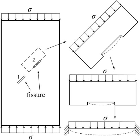
FIGURE 11. Double-clamped beam model.
Thus, the normal stress
When the fissure is pressed to closure, the effective shear force acting on the crack surface is (Horii and NematNasser., 1986; Li et al., 2007; Sun et al., 2018)
Where
Substituting Eqs 1, 2 into Eq. 3 to obtain the effective shear force equation, see Eq. 4.
The normal stress on the fissured surface can be simplified into a double-clamped beam model (Zhang et al., 2018; Zeng et al., 2020; Sun et al., 2022), as shown in the figure for the analysis.
According to structural mechanics, the torque of the fixed end is:
The torque at the center is:
The maximum deflection in the middle is:
The tensile stress at the middle of the section under the action of the bending moment is
The tensile stress at both ends of the section under the action of the bending moment is
Considering the influence of crack 1 on crack 2, the tensile stresses at both ends are:
When α = 0°, there is no shear stress at the crack tip, and the fracture behavior can be explained by the double-clamped beam. For the four groups of rock samples with α = 0°, as shown in Figure 6, cracks can easily appear at either the tip or middle of the fissure. When the double-clamped beam is subjected to a uniform vertical load, the mid-span experiences the greatest bending moment and deflection, causing cracks to form in the middle of the fissure. However, cracks in the α = 0° rock are mostly generated at the fissure tip, on the one hand, the tensile stress of the fissure tip is larger. In addition, the upper and lower crack surfaces first contact and produce closure when the crack is deformed, hindering the generation of tensile cracks in the middle of the crack. This is related to the crack opening degree. In this test, the thickness of the cracks is 0.5 mm thick. If the thickness of the cracks is increased, the deflection deformation of the fissure surface will induce cracks in the middle of the crack to increase (Zeng et al., 2020).
When α = 30°, 45°, and 60°, shear stress exists between the cracks. The shear slide along the shear plane of the generated shear crack occurs during the loading process, as shown in Figure 12. The white wear zone caused by the shear slide is also shown.
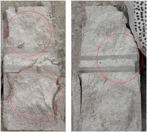
FIGURE 12. Shear stress wear zone.
According to the force analysis diagram in Figure 13, after the fissure is pressed to close, the shear force generated is composed of the shear stress and the friction formed by the normal stress on the fissure surface. When the crack is not pressed to closure, there is only shear stress and no friction, which can be regarded as
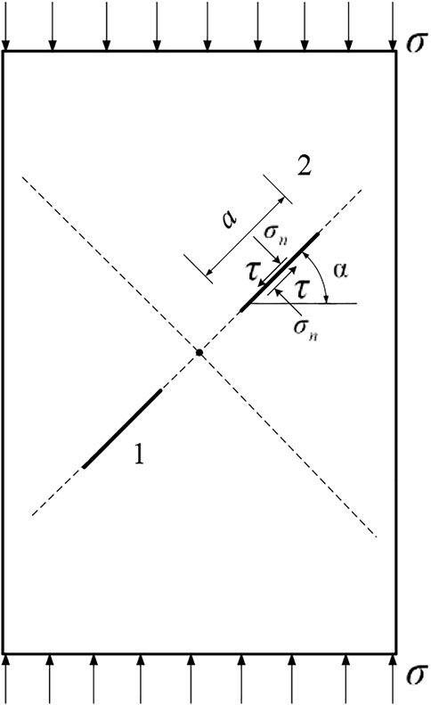
FIGURE 13. Force analysis diagram of fissure sample.
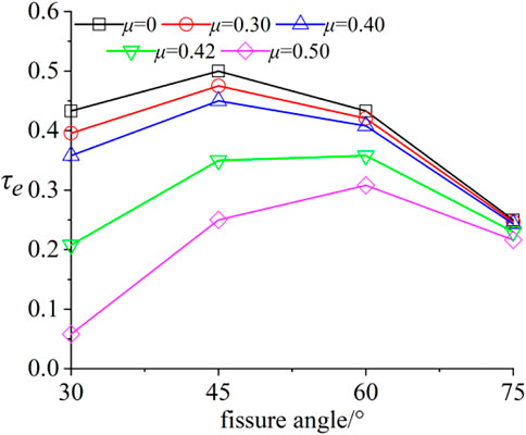
FIGURE 14. The relation between
When α = 90°, it can be seen from the above model that when the effective shear force is
4 Conclusion
(1) The peak stress and elastic modulus increased when the fissure angle increased. With an increase in the rock bridge length, the change in the peak stress of the rock sample is smaller, the elastic modulus shows a trend of decreasing and then increasing, with a small variation range. The influence of bridge length on rock samples was weaker than that of the fissure angles’ influence.
(2) Rock sample damage characteristics are as follows: under the same bridge length, the number of cracks tends to decrease significantly with an increase in the fissure angle, and the main damage crack changes from two to one; the number of surface spalling blocks decreases and the area of spalling blocks increases; the bridge connection occurs only at a high fissure dip angle; Under the same fissure angle, with the increase of the length of rock bridge, the surface crack propagation and spalling block failure characteristics are basically the same. The difficulty of the rock bridge to connect at the fissure angle increases as the length of the bridge itself increases. (3) The damage mechanism primarily manifests as follows: at a low fissure angle, tensile damage cracks are dominant, and shear damage cracks are rare. With an increase in the fissure angle, the damage mode changes from tensile damage cracks to shear damage cracks to form a mixed tensile-shear damage mode. With an increase in the rock bridge length, the bridge changes from a direct connection to either an indirect connection or no connection. Simultaneously, the damage mechanism of the rock sample changes from mixed tensile-shear cracks to increased tensile cracks.
(4) Based on a simplified analysis of the force on the coplanar double-fissured rock sample, the failure behavior of the rock sample was affected by the normal stress double-clamped beam model and shear stress. The rock sample was dominated by tensile failure, and the proportion of shear failure increased as the fissure angle also increased.
Data availability statement
The datasets presented in this study can be found in online repositories. The names of the repository/repositories and accession number(s) can be found in the article/Supplementary Material.
Author contributions
Conceptualization: DZ and TX; methodology: DZ and TX; software: DZ and TX; formal analysis: DZ and HS; data curation: DZ, TX, and HS; writing—original draft preparation: DZ and TX; writing—review and editing: DZ and TX; supervision: TX; project administration: TX and HS; funding acquisition: TX. All authors have read and agreed to the published version of the manuscript.
Funding
This work was supported by the Hubei Provincial Science and Technology Plan Project Foundation of China (Grant No. 2020AC15) and the Shanxi Provincial Key Laboratory of Concrete Structure Safety and Durability Open Fund of China (Grant No. SZ02105), the Open Fund for the State Key Laboratory of Geomechanics and Engineering of China (Grant No. Z020013), Hubei Key Laboratory of Oil and Gas Drilling and Production Engineering (Yangtze University) (No: YQZC202204), and Key Laboratory of well Stability and Fluid and Rock Mechanics in Oil and Gas Reservoir of Shaanxi Province (Grant No. SFRM20210101001).
Conflict of interest
The authors declare that the research was conducted in the absence of any commercial or financial relationships that could be construed as a potential conflict of interest.
Publisher’s note
All claims expressed in this article are solely those of the authors and do not necessarily represent those of their affiliated organizations, or those of the publisher, the editors and the reviewers. Any product that may be evaluated in this article, or claim that may be made by its manufacturer, is not guaranteed or endorsed by the publisher.
References
Bobet, A. (2000). The initiation of secondary cracks in compression. Eng. Fract. Mech. 66 (2), 187–219. doi:10.1016/s0013-7944(00)00009-6
Cao, P., Liu, T., Pu, C., and Lin, H. (2015). Crack propagation and coalescence of brittle rock-like specimens with pre-existing cracks in compression. Eng. Geol. 187, 113–121. doi:10.1016/j.enggeo.2014.12.010
Cao, P., Liu, T., Pu, C., and Lin, H. (2015). Crack propagation and coalescence of brittle rock-like specimens with pre-existing cracks in compression. Eng. Geol. 187, 113–121. doi:10.1016/j.enggeo.2014.12.010
Chen, M., Jing, H., Ma, X., and Zhu, T. (2017). Fracture evolution characteristics of sandstone containing double fissures and a single circular hole under uniaxial compression. Int. J. Min. Sci. Technol. 27 (3), 499–505. doi:10.1016/j.ijmst.2017.03.027
Chen, Y. (1984). Multiple crack problems in an infinite plate. Journal of Northwestern Polytechnical University, (04) 367–379.
Gong, C-G., Wang, W., Shao, J-F., Wang, R-B., and Feng, X-W. (2020). Effect of water chemical corrosion on mechanical properties and failure modes of pre-fissured sandstone under uniaxial compression. New York, NY: Acta Geotechnic. doi:10.1007/s11440-020-01071-y
He, M., Sui, Q., Li, M., Wang, Z., and Tao, Z. (2022). Compensation excavation method control for large deformation disaster of mountain soft rock tunnel. Int. J. Min. Sci. Technol. 32 (5), 951–963. doi:10.1016/J.IJMST.2022.08.004
Hoek, E., and Martin, C. D. (2014). Fracture initiation and propagation in intact rock–a review. J. Rock Mech. Geotechnical Eng. 6 (4), 287–300. doi:10.1016/j.jrmge.2014.06.001
Horii, H., and NematNasser, S. (1986). Brittle failure in compression: Splitting, faulting and brittle-ductile transition. London, United Kingdom: Philosophical Transactions of the Royal Society of London. Series A, Mathematical and Physical Sciences. doi:10.1098/rsta.1986.0101
Janeiro, R. P., and Einstein, H. H. (2010). Experimental study of the cracking behavior of specimens containing inclusions (under uniaxial compression). Int. J. Fract.164, 83, 102. doi:10.1007/s10704-010-9457-x
Jin, J., Cao, P., Chen, Y., Pu, C., Mao, D., and Fan, X. (2017). Influence of single flaw on the failure process and energy mechanics of rock-like material. Comput. Geotechnics 86, 150–162. doi:10.1016/j.compgeo.2017.01.011
Lajtai, E. Z., Carter, B. J., and Ayari, M. L. (1990). Criteria for brittle fracture in compression. Eng. Fract. Mech. 37 (1), 59–74.
Lajtai, E. Z. (1969).Shear strength of weakness planes in rock. In Int. J. Rock Mech. Min. Sci. Geomechanics Abstr. 6. Pergamon, 499–515.
Li, Y., Wu, Y., and Yang, C. (2007). Comparison of sliding crack models for rock-like materials. Chin. J. Rock Mech. Eng. (02), 278–284. CNKI:SUN:YSLX.0.2007-02-007.
Liang, Xin, Tang, Shibin, Tang, Chun’an, Hu, Lihua, and Chen, Feng (2022). Influence of water on the mechanical properties and failure behaviors of sandstone under triaxial compression. Rock Mech. Rock Eng. 56 (2), 1131–1162. doi:10.1007/S00603-022-03121-1
Liang, Z. Z., Xing, H., Wang, S. Y., Williams, D. J., and Tang, C. A. (2012). A three-dimensional numerical investigation of the fracture of rock specimens containing a pre-existing surface flaw. Comput. Geotechnics 45, 19–33. doi:10.1016/j.compgeo.2012.04.011
Park, C. H., and Bobet, A. (2009). Crack coalescence in specimens with open and closed flaws: A comparison. Int. J. Rock Mech. Min. Sci. 5, 819–829. doi:10.1016/j.ijrmms.2009.02.006
Park, C. H., and Bobet, A. (2010). Crack initiation, propagation and coalescence from frictional flaws in uniaxial compression. Eng. Fract. Mech. 77 (14), 2727–2748. doi:10.1016/j.engfracmech.2010.06.027
Prudencio, M., and Van Sint Jan, M. (2007). Strength and failure modes of rock mass models with non-persistent joints. Int. J. Rock Mech. Min. Sci. 44 (6), 890–902. doi:10.1016/j.ijrmms.2007.01.005
Pu, C, Z., Cao, P., Zhao Y, L., Zhang, X. Y., Yi Y, L., and Liu Y, K. (2010). Numerical analysis and strength experiment of rock-like materials with multi-fissures under uniaxial compression. Rock Soil Mech. (11), 3661–3666. doi:10.16285/j.rsm.2010.11.038
Ren, F. Q., Zhu, C., He, M. C., Shang, J. L., Feng, G. L., and Bai, J. W. (2023). Characteristics and precursor of static and dynamic triggered rockburst: Insight from multifractal. Rock Mech. Rock Eng. 56, 1945–1967. doi:10.1007/s00603-022-03173-3
Sun, B., Zou, C., Zeng, S., Fang, Y., and Wang, F. (2018). Failure characteristics of rock-like mass with different fracture types under uniaxial compression. J. Disaster Prev. Mitig. Eng. (06), 959–966. doi:10.13409/j.cnki.jdpme.2018.06.009
Sun, B., Zou, C. H., Zhen, S., Fang, Y. C., and Wang, F. L. (2018). Failure characteristics of rock-like mass with different fracture types under uniaxial compression . J. Disaster Prev. Mitig. Eng. 38(6), 959–966. doi:10.13409/j.cnki.jdpme.2018.06.009
Sun, H., Chen, S., Jin, A., and Zhu, D. (2022). Uniaxial compressive strength characteristics and crack evolution laws of rock-like samples with flaws. J. Northeast. Univ. Sci. (03), 404–413. CNKI:SUN:DBDX.0.2022-03-014.
Tang, Shibin, Li, Jiaming., Ding, Shun, and Zhang, Leitao (2022). The influence of water-stress loading sequences on the creep behavior of granite. Bull. Eng. Geol. Environ. 81, 482. doi:10.1007/s10064-022-02987-3
Wang, F., Cao, P., Cao, R. H., Gao, Q. P., Xiong, X. G., and Wang, Z. (2018)Influence of parallel joint interaction on mechanical behavior of jointed rock mass . J. Central South Univ. Technol. 49(10):2498–2507.
Wang, Min, Wen, Wan, and Zhao, Yanlin (2020). Experimental study on crack propagation and the coalescence of rock-like materials with two preexisting fissures under biaxial compression. Bull. Eng. Geol. Environ. 79, 3121–3144. doi:10.1007/s10064-020-01759-1
Wang, Q., Xu, S., Xin, Z., He, M., Huayong, W., and Jiang, B. (2022). Mechanical properties and field application of constant resistance energy-absorbing anchor cable. Tunn. Undergr. Space Technol. incorporating Trenchless Technol. Res. doi:10.1016/J.TUST.2022.104526
Wang, Y., Tang, J., Dai, Z., and Yi, T. (2018). Experimental study on mechanical properties and failure modes of low-strength rock samples containing different fissures under uniaxial compression. Eng. Fract. Mech. 197, 1–20. doi:10.1016/j.engfracmech.2018.04.044
Wasantha, P. L. P., Ranjith, P. G., Viete, D. R., and Luo, L. (2012). Influence of the geometry of partially-spanning joints on the uniaxial compressive strength of rock. Int. J. Rock Mech. Min. Sci. 50, 140–146. doi:10.1016/j.ijrmms.2012.01.006
Wong, L. N. Y., and Einstein, H. H. (2008). Systematic evaluation of cracking behavior in specimens containing single flaws under uniaxial compression. Int. J. Rock Mech. Min. Sci. 46 (2), 239–249. doi:10.1016/j.ijrmms.2008.03.006
Wong, L. N. Y., and Einstein, H. H. (2009). Systematic evaluation of cracking behavior in specimens containing single flaws under uniaxial compression. Int. J. Rock Mech. Min. Sci. 46 (2), 239–249. doi:10.1016/j.ijrmms.2008.03.006
XI, J., Zhong-hui, C., Zhu, D., and Chen, Q. (2015). Stress intensity factors and initiation of unequal collinear cracks in rock. Chin. J. Geotechnical Eng. (04), 727–733.
Xiao, T. L., Li, X. P., and Guo, Y. H. (2012). Experimental study of failure characteristic of single jointed rock mass under triaxial compression tests. Rock Soil Mech. 33 (11), 3251–3256. doi:10.16285/j.rsm.2012.11.008
Xiao, T. L., Li, X. P., and Jia, S. P. (2015). Failure characteristics of rock with two pre-existing transfixion cracks under triaxial compression. Chin. J. Rock Mech. Eng. (12), 2455–2462. doi:10.13722/j.cnki.jrme.2014.1443
Xiao, Y., Qiao, Y., He, M., Li, H., Cheng, T., and Tang, J. (2022). A unified strain-hardening and strain-softening elastoplastic constitutive model for intact rocks. Comput. Geotechnics 148, 104772. doi:10.1016/J.COMPGEO.2022.104772
Xu, T., Ranjith, P. G., Wasantha, P. L. P., Zhao, J., Tang, C., and Zhu, W. C. (2013). Influence of the geometry of partially-spanning joints on mechanical properties of rock in uniaxial compression. Eng. Geol. 167, 134–147. doi:10.1016/j.enggeo.2013.10.011
Yang, S-Q., Huang, Y-H., Tian, W-L., and Zhu, J-B. (2017). An experimental investigation on strength, deformation and crack evolution behavior of sandstone containing two oval flaws under uniaxial compression. Eng. Geol. 217, 35–48. doi:10.1016/j.enggeo.2016.12.004
Yang, S. Q. (2011). Crack coalescence behavior of brittle sandstone samples containing two coplanar fissures in the process of deformation failure. Eng. Fract. Mech. 78 (17), 3059–3081. doi:10.1016/j.engfracmech.2011.09.002
Yang, S. Q., Dong, J. P., Yang, J., Yang, Z., and Huang, Y. H. (2022). An experimental investigation of failure mechanical behavior in cylindrical granite specimens containing two non-coplanar open fissures under different confining pressures. J. Central South Univ. 29 (5), 1578–1596. doi:10.1007/s11771-022-5035-4
Yang, S. Q., and Jing, H. W. (2011). Strength failure and crack coalescence behavior of brittle sandstone samples containing a single fissure under uniaxial compression. Int. J. Fract. 168 (2), 227–250. doi:10.1007/s10704-010-9576-4
Yang, S. Q., and Jing, H. W. (2011). Strength failure and crack coalescence behavior of brittle sandstone samples containing a single fissure under uniaxial compression. Int. J. Fract. 168 (2), 227–250. doi:10.1007/s10704-010-9576-4
Yang, S. Q., Liu, X. R., and Jing, H. W. (2013). Experimental investigation on fracture coalescence behavior of red sandstone containing two unparallel fissures under uniaxial compression. Int. J. Rock Mech. Min. Sci. 63, 82–92. doi:10.1016/j.ijrmms.2013.06.008
Yin, P., Wong, R. H. C., and Chau, K. T. (2014). Coalescence of two parallel pre-existing surface cracks in granite. Int. J. Rock Mech. Min. Sci. 68, 66–84. doi:10.1016/j.ijrmms.2014.02.011
Zeng, J-j., Zhang, Z-j., Zhang, X-x., and Pu, C-z. (2020). Fracture test and analysis of horizontal fissure rock-like specimens influenced by apertures. Chin. J. Geotechnical Eng. (03), 523–532. doi:10.11779/CJGE202003014
Zhang, K., Liu, X., Kun, L. I., and Wu, W. (2018). Investigation on the correlation between mechanical characteristics and fracturing fractal dimension of rocks containing a hole and multi-flaws. Chin. J. Rock Mech. Eng. (12), 2785–2794. doi:10.13722/j.cnki.jrme.2018.0894
Zhang, P., Li, N., and He, R. L. (2006). Mechanism of fracture coalescence between two pre-existing flaws under dynamic loading. Chin. J. Rock Mech. Eng. 25(6):1210–1217.
Zhang, P., Li, N., He, R. L., and Xu, J, G. (2006). Mechanical properties of fractured media containing intermittent fractures at different strain rates. Chin. J. Geotechnical Eng. 06, 750–755. CNKI:SUN:YTGC.0.2006-06-014.
Zhang, Y., Jiang, Y., Asahina, D., and Wang, C. (2020). Experimental and numerical investigation on shear failure behavior of rock-like samples containing multiple non-persistent joints. Wien, Austria: Rock Mechanics and Rock Engineering. doi:10.1007/s00603-020-02186-0
Keywords: sandstone-like, coplanar double fissures, fissure angle, rock bridge length, DIC technique
Citation: Zhang D, She H and Xiao T (2023) Influence of coplanar double fissures on failure characteristics of sandstone and fracture mechanics analysis. Front. Earth Sci. 11:1180636. doi: 10.3389/feart.2023.1180636
Received: 06 March 2023; Accepted: 05 April 2023;
Published: 19 April 2023.
Edited by:
Shuren Wang, Henan Polytechnic University, ChinaCopyright © 2023 Zhang, She and Xiao. This is an open-access article distributed under the terms of the Creative Commons Attribution License (CC BY). The use, distribution or reproduction in other forums is permitted, provided the original author(s) and the copyright owner(s) are credited and that the original publication in this journal is cited, in accordance with accepted academic practice. No use, distribution or reproduction is permitted which does not comply with these terms.
*Correspondence: Haicheng She, NTIxMDIxQHlhbmd0emV1LmVkdS5jbg==; Taoli Xiao, MjAwNTM2QHlhbmd0emV1LmVkdS5jbg==