
95% of researchers rate our articles as excellent or good
Learn more about the work of our research integrity team to safeguard the quality of each article we publish.
Find out more
ORIGINAL RESEARCH article
Front. Earth Sci. , 15 May 2023
Sec. Economic Geology
Volume 11 - 2023 | https://doi.org/10.3389/feart.2023.1180501
This article is part of the Research Topic Advances in Exploration and Exploitation of Deep and Ultra-Deep Shale Oil and Gas View all 7 articles
 Nan Li1*
 Weidong Jiang2Yixin Jiang3Jinmin Yang4Guangqiang Cao1Rui Zheng3Daqiang Feng5Haoyu Wang1Zhiyu Xu5Bin Peng4Furong Li4Ruixin Kang5
 Qiubo Wu1*
Foam drainage gas production is a gas production technology for low-pressure gas well in domestic and abroad industries. In Qinghai Oilfield’s Sebei Gasfield, sand existence often occurs during drainage production. In order to reveal the impacts of formation sands on drainage gas production, a lab test was conducted to make a study on foam performances of different foam drainage agents in case of sand existence. A laboratory test was employed to study the foam performances of different foam drainage agents under varies scenes of sand existence, to reveal the impacts of formation sands during foam drainage gas recovery. In this study, four foam drainage agents, i.e., OP-10, Sodium dodecyl benzene sulfonate, Hexadecyl Trimethyl Ammonium Bromide (CTAB), and Lauramidopropyl Hydroxy Sulfobetaine, were selected to compare with the field compound foam drainage agent QH-X1. Following patterns can be revealed by macroscopic and microscopic experimental results: Foam formed by an ionic-type foam drainage agent is more stable when the hydrophilic sand particles are smaller (which means they have larger specific surface areas and the adsorption energy levels between the sand and bubbles are higher); while foam formed by non-ionic foam drainage agent OP-10 has a short stable period because its polarity is weaker than that of ionic-type agent foam and the adsorbability of the foam on the hydrophilic particles is weak; under different sand conditions, the impacts of different foam drainage agent types on the average bubble area, bubble wall thickness, and Plateau Boundary are markedly different, and appear decreasing tendency with anionic foam drainage agents, is the trend can be more obvious when the sand particles are coarser. The study on QH-X1 shows that the foam parameters are generally lower as the sand particles are smaller, but the changing trends can be different after sand is involved. Particles constitute an adsorption film at the gas-liquid interface and a laminar structure within each interbubble thin liquid film, thus improving bubble coalescence and unloading stability. So, the inflow of the hydrophilic sands increases the stiffness, half-life period, and comprehensive rate of the QH-X1-induced foam.
Natural gas production is a process during which the formation pressure continuously drops. When the formation pressure drops and the gas flow rate in the wellbore accordingly decreases to a certain degree, the condensate and formation water accumulated at the bottom of the well cannot be brought out. In addition, edge and bottom water advances and stimulation treatments such as hydraulic fracturing and acidization lead to more and more bottom-hole liquid accumulation. These factors trigger the gas-well liquid accumulation issue (Guo et al., 2018). When the weight of the liquid accumulation is greater than the formation pressure, a hydrostatic backpressure is imposed on the gas reservoir so that the gas well cannot produce gas normally and might have to be shut in (Yang et al., 2013). The commonly used approaches of effectively unloading the accumulated liquid at the bottom of the well and improving the bottom-hole flow pressure (Solesa, 2006) include jet pumping, ESP, gas lift, foam unloading, etc. (Huang et al., 2005). Among these methods, foam unloading gas production is the preferred one at home and abroad because it features simple equipment, easy operation and management, low cost, etc. (Zhang et al., 2005; Jiang et al., 2007; Van Nimwegen et al., 2015).
The implementation of the foam unloading gas production process can be traced back to the early 20th century. It was not put into production due to technical imperfection until a US company conducted a successful foam unloading or drive simulation test, on the basis of which some developed countries, such as USSR, US, and Canada, applied this technology for gas-well unloading with good results (Bluestein and Hitton, 1982). There are two types of foam drainage agents commonly used in the field, i.e., solid and liquid foam drainage agents. Liquid foam drainage agents: anionic, cationic, zwitterionic, non-ionic, high polymer-type, and compound-type foam drainage agents; solid foam drainage agents: slide bar, acidic bar, and bubble bar (Pandey et al., 2003; Li et al., 2015).
In some block of Qinghai Oilfield’s Sebei Gasfield, unloading gas production wells encountered the serious sand existence problem that can affect foam performance and gas production. In order to deeply reveal the impacts of sands on unloading gas production, a lab test was conducted to make a study on foam performances of different foam drainage agents in case of sand existence. Researches at home and abroad have carried out extensive research into the performances of the foam drainage agents used in gas wells. By taking advantage of the synergetic effect of the cationic surface active agent SDS, the zwitterionic surface active agent CHSB, and the fluorocarbon surface active agent PFBS, Qu et al. (2020) developed the oil-resistant foam drainage agent COT, whose field application has produced good results. Through two reactions involving dimethyl oleylamine-propylamine, sodium 2-hydroxy-3-chloropropyl sulfonate, and 1, 4-dibromobutane as main raw materials, Qi et al. (2018) synthesized a new-type Gemini betaine surfactant B18-4-18 for high-salinity and high-condensate gas wells, which can effectively improve the liquid-carrying efficiency. Seeing that this system had poor performance adaptability and high cost when applied in gasfields featuring high temperature, high salinity, high acidic gas content, and high condensate content, Xiong et al. (2019) developed a series of nanoparticle foam drainage agents applicable for the main gasfields in China, by using the Gemini surface active agent as the dominant agent to improve the foaming and foam stabilizing performances of the foam drainage agent and using graft-modified nanoparticles as the foam stabilizer agent to further enhance the stability of the formed foam. Xu (2022) developed the new-type, condensate-resistant compound foam drainage agent CSL involving hydrocarbyl polyether carboxylate and hydrocarbyl polyether betaine as effective constituents. This foam drainage agent excels in salt resistance, oil resistance, and high temperature resistance. Seeing that Yan 113 Gasfield has high bottom-hole temperature and that its produced water is high-salinity and high-condensate, Zhang et al. (2021) developed a foam drainage agent with good foaming performance and foam stability under high-temperature, high-salinity, and high-condensate conditions, which can dramatically improve gas well productions. In addition, to add a protein, a high polymer, and nanoparticles into the surfactant solution can improve the stability of the pseudo-emulsion films and the viscosity of the bubble liquid films, mitigate the foam coalescence and coarsening, and enhance the stability of the foam (Fameau and Salonen, 2014).
Wang et al. (2016) explored the impacts of the hydrophobicity, size, and shape of solid particles on the liquid film or foam stability (Wang et al., 2016; Honaker and Ozsever, 2003) and (Rahman et al., 2012) designed special floatation columns capable of collecting particles desorbed from the foam phase. Rahman et al. (2012) found that the particle desorption from the foam phase is affected mainly by the collecting agent usage, volume of gas charged, and concentration of fine particles. ATA (2012) studied the impact of hydrophobic, fine-particle glass beads on the hematite recovery ratio and found that moderately hydrophobic glass beads can deliver the highest recovery ratio of hematite desorbed from the foam phase. On some other occasions, however, fine particles reduce the recovery ratio of coarse particles. Tao (2005) put forward the proposition that the presence of fine particles destroys the foam stability and hinders the recovery of coarse particles in the floatation column. Wu Junwen et al. synthesized an efficient foam drainage agent by using a comb-like Gemini cationic surfactant as its main agent and nanoparticles as the foam stabilizing agent (Wu et al., 2018). Dippenaar analyzed the impact of solid particles on the foam stability in the high-speed track way and concluded that the hydrophobicity, size, and shape of solid particles affect the stability of the bubble films (Dippenaar, 1982a; Dippenaar, 1982b). Frye and Berg developed a theoretical model representing the impact of the solid particle contact angle on the foam unloading process, with the aim of revealing the mechanism of the impact of the gas-liquid interface changes on both sides of the liquid film on the particle on the liquid film rupture. Gareth and Morris (2014) captured the bridging process of solid particles on the bubble film as well as its impact on film rupture and foam coalescence.
As the key to the foam unloading gas production process, foam performance not only is affected by the inherent properties of the foam drainage agent and foam stabilizer but also is interfered by external environmental factors, such as bottom-hole temperature, formation water’s salinity, string characteristics, etc. Although researchers have conducted in-depth studies on the impacts of sands on bubble films, no studies specific to the formation sand characteristics of the study block in Sebei Gasfield have been yet conducted. So, this paper presents a lab test study into foam performance differences of different foam drainage agents in case of sand existence, thus providing guidance on unloading foam drainage agent selection and process optimization for wells with sand existence.
In order to make the study results more accurate, the particle sizes, roundness, sphericity, and composition of the sands produced in the field were analyzed before the foam performances of the different foam drainage agents in case of sand existence were studied, and then, the Warning Blender method was used to explore the impacts of the properties of the sands on the foam stability.
The Warning Blender method is a simple method of evaluating the foam performance with few constraints, and can be used as one of the standard evaluation methods. Using experimental instruments such as high-speed stirrer, electronic balance, stopwatch, measuring cylinder, and other conventional instruments and featuring simple procedure, short cycle, high repetition rate, simultaneous measurements of the two independent parameters of foam volume and half-life, the method can reflect the foaming difficulty level, number of bubbles, and foam stability. The comprehensive foam rating of a foam drainage agent is the multiplication of foam volume and half-life and can reflect its comprehensive performance. It is defined as:
Fc is the comprehensive foam rating (ml*min), V0 is the foam volume, and T1/2 is the half-life (min).
In addition, an optical microscope was used to investigate the microstructural characteristics of the foams so as to deeply analyze the foam performances of different foam drainage agents in case of sand existence, and the influence mechanism of the sands on the foam performance was explained from both macroscopic and microscopic perspectives.
0–600-mesh standard splitting sieves were used to sieve the sand samples. From formation sand particle size (Figure 1A) and its distributions (Figures 1B–D), it can be seen that: sands within the particle size range of 0.074–0.385 mm (400–200-mesh particles) accounted for 96.86% of its total mass. This portion of sands was the main study object.
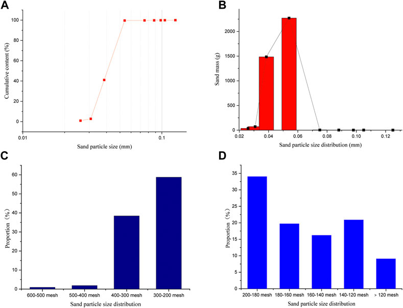
FIGURE 1. Particle Size Distribution of Field Sand Samples (A) Cumulative distribution of formation sand with different particle size; (B) Mass distribution of formation sand with different particle size; (C) Mass distribution of formation sand with particle size less than 200 mesh; (D) Mass distribution of formation sand with particle size greater than 200 mesh).
The particle roundness and sphericity of the sand samples were observed under an optical microscope when it was magnified to 40 times. The specific data results are given in Figure 2. A roundness and sphericity analysis of the sands produced in the field shows the following characteristics: 1) the roundness is generally relatively low, with an average of 0.30 and the tendency to decrease as the particle size increases; 2) the sphericity is relatively high, with an average of 0.79 and at a plateau in general.
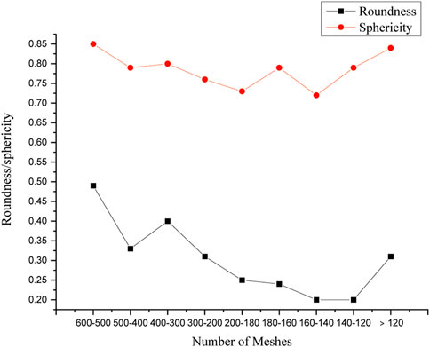
FIGURE 2. Roundness and sphericity distributions of sand samples from sieves with different numbers of meshes.
The composition of the sands produced in the field was measured through using a Rigaku TTRIII multifunctional X-ray diffractometer and according to the X-ray diffraction analysis procedure for clay minerals and ordinary non-clay minerals in sedimentary rocks, that is, specified in SY/T 5163-2018. The measurement results are given in Table 1; Figure 3.
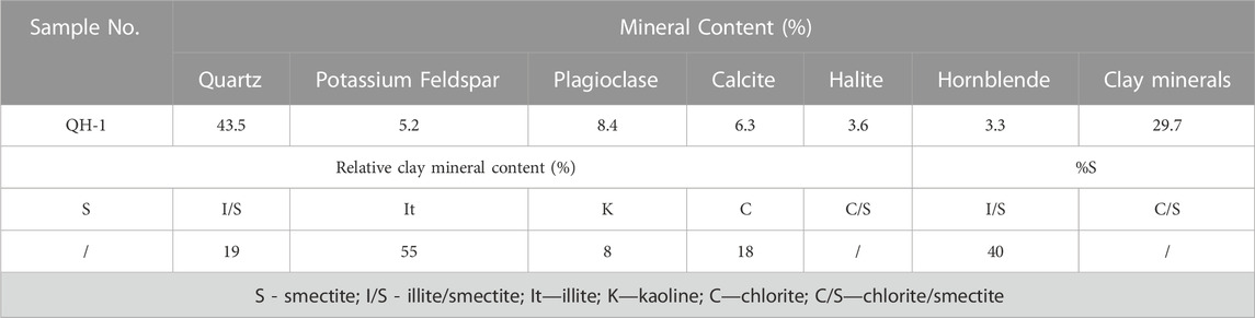
TABLE 1. X-ray diffraction data of whole-rock minerals.
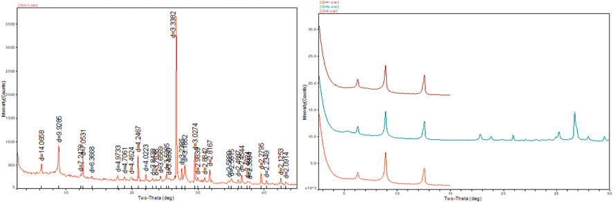
FIGURE 3. X-ray diffraction diagrams for non-clay and clay minerals.
The above data show that the sands produced in the field are mainly composed of quartz (43.5%) and clay minerals (29.7%), both of which account for 73.2% of all the minerals; as the main clay minerals therein, illite (55%) and illite/smectite (19%) account for 74% of all the clay minerals. A composition analysis of the produced sands shows that they are hydrophilic because quartz, illite, and illite/smectite are easy to be wetted by water, and their hydrophilicity affects foaming performances of foam drainage agents and thus the foam stability.
Due to their different chemical structures, different types of foam drainage agents will cause different foam performance when interacting with formation sands. Therefore, four typical foam drainage agents representing anionic type (Sodium Dodecyl Benzene Sulfonate), cationic type (Sodium cetylbenzene sulfonate), zwitterionic type (Lauramidopropyl Hydroxy Sulfobetaine) and non-ionic type (OP-10) are selected in the experiment to explore the influence of formation sands on foam properties during drainage gas production. In addition, a foam performance comparison with the compound foam drainage agent QH-X1 used in the field was made to explain the influences of different foam drainage agent types on foam stability in case of sand existence.
According to the annual water and sand production data of more than 1,000 wells in the study block in the gasfield, the volumetric sand/water ratio was set as 3:100 for the experiments. This value is close to the actual daily sand production in the field. The particle size analysis of the sand samples presented in Section 2.1 shows that the 200–400-mesh sand sample is the main study object that affects the field foam performance. So, the performance influences of sands on the foam drainage agents were analyzed with regard to 200–300-mesh sands and 300–400-mesh sands. The specific study results are given as follows.
The following can be known from Figure 4A: for cationic and anionic foam drainage agents, the volumes of the two foam systems containing 200–300-mesh sands are smaller than those of the foams containing no sands respectively; for zwitterionic and non-ionic foam drainage agents, the volumes of the foams gradually decrease as the number of meshes increases, but the volume difference between the sand-free foam and the foam containing 200–300-mesh sands is not considerable when a zwitterionic foam drainage agent is used and the volume difference between the foam containing 200–300-mesh sands and the foam containing 300–400-mesh sands is not considerable when a non-ionic foam drainage agent is used; for QH-X1, the volume of the foam containing sands is larger than that of the foam containing no sands, but the volume of the foam containing 300–400-mesh sands is smaller than that of the foam containing 200–300-mesh sands. The following can be known from Figure 4B: for anionic, cationic, and zwitterionic foam drainage agents, the half-life of each of the foams containing 200–300-mesh sands is shorter than that of the foam containing no sands, but the half-life of the foam containing 300–400-mesh sands is longer than that of the foam containing 200–300-mesh sands; as the number of meshes increases, the half-life of the foam formed by using the non-ionic foam drainage agent gradually decreases, while QH-X1 shows an opposite trend, i.e., the half-life of the foam gradually increases as the particle size of the inflow sands increases (this is relevant to whether the sands are hydrophilic or hydrophobic). The comprehensive foam rating change trends under different particle size conditions as shown in Figure 4C are consistent with the half-life change trends as shown in Figure 4B.
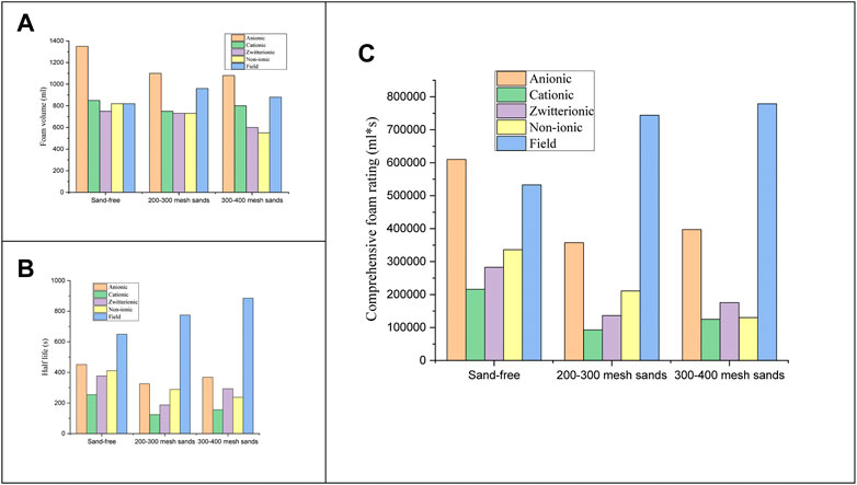
FIGURE 4. Foam Performances in Case of Sand existence and No Sands (A) Foam Volumes under Different Particle Size Conditions; (B) Foam Half-life Values under Different Sand Particle Size Conditions; (C) Comprehensive Foam Ratings under Different Sand Particle Size Conditions).
To sum up, the influences of sands on foam performances of different foam drainage agents are different because their types are different. In addition, according to the X-ray diffraction-based sand composition analysis results presented in Section 2.4, the main constituents of the sand sample are quartz, illite, and illite/smectite easy to be wetted by water, thus showing hydrophilicity. For QH-X1, the hydrophilic sands enhance the stiffness of the foam, extend its half-life, and improve the foam’s comprehensive rating. The foam-stabilizing mechanism of sand particles can be regarded as consisting of three parts: 1) the adsorption film formed by particles at the gas-liquid interface makes the foam coalescence and disproportionation more stable; 2) the laminar structure formed by particles within the inter-bubble thin film enhances the foam unloading stability, maximum capillary pressure, and foam coalescence stability; 3) the inter-bubble bridging process greatly improves the foam stability (Qian, 2010).
In order to more deeply explore the impacts of sands on foaming performances of foam drainage agents, the microscopic structure changes of the foams were observed under an optical microscope at 40 times magnification in case of sand existence and their shape change patterns were analyzed from the microscopic perspective. The microscopic foam structure differences between Sodium Dodecyl Benzene Sulfonate and QH-X1 are shown in Figures 5, 6.
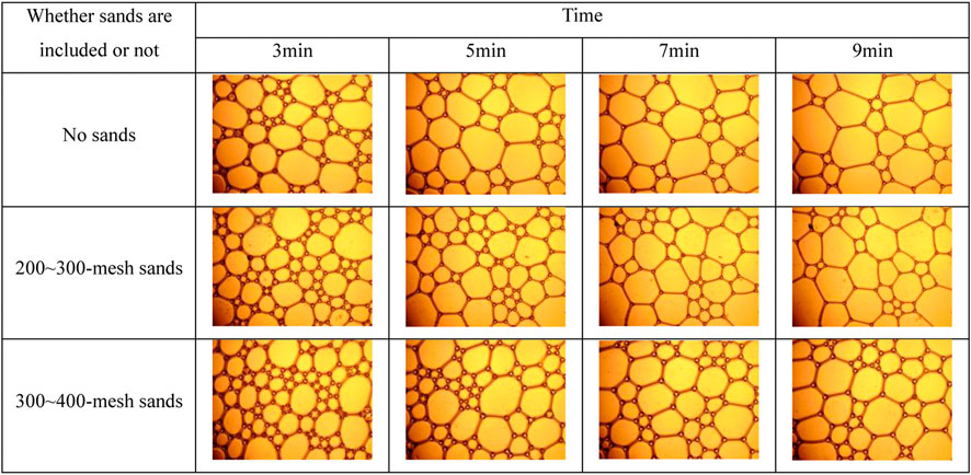
FIGURE 5. Microscopic shape characteristics of sodium dodecyl benzene sulfonate-induced foam.
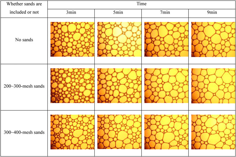
FIGURE 6. Microscopic shape characteristics of QH-X1-induced foam.
The microscopic observations show the following: as time passes, the bubbles change from wet state to dry state and the shape of each of them changes from the spheric shape to a polyhedron; the roundness degrees and quantities of bubbles formed by cationic and anionic foam drainage agents are obviously smaller than those of zwitterionic and non-ionic foam drainage agents and the field compound foam drainage agent QH-X1; as time passes, the number of bubbles gradually decreases and the bubble coalescence phenomenon is increasingly more obvious, but there are considerable foam coalescence stability differences between different foam drainage agent types (this is related to the drainage rate of the foam). The higher the drainage rate is, the more instable the foam is and the more obvious the foam agglomeration trend is; vice versa, a low drainage rate means that the foam formed by the foam drainage agent has good stability. The drainage speed is closely related to the molecular structure of the foam drainage agent, whether the sands are hydrophilic or hydrophobic, the particle size of the sands, etc.
In order to better explain the relationship between number of bubbles and drainage rate, a foam drainage rate comparison between different numbers of meshes, as shown in Figure 7, was made. The following can be known according to the figure: the foam drainage rates of the anionic, cationic, and zwitterionic foam drainage agents containing no sands are lower than those in case of sand existence, but the drainage rate when 200–300-mesh sands are included is higher than that when 300–400-mesh sands are included, indicating that the presence of sands promotes the coalescence of bubbles formed by the ionic foam drainage agents but the particle sizes of the sands included affect the bubble coalescence speed; in case of sand existence and sand particle size reduction, the drainage rate of the foam formed by the non-ionic foam drainage agent gradually increases and its coalescence speed also gradually increases; QH-X1 shows an opposite result, and compared with the other agent types, the foam formed by it has a steady and slow drainage rate change. This is consistent with the macroscopic experiment results given in Section 3.1. The following are average bubble area, foam wall thickness, and plateau boundary studies for Sodium Dodecyl Benzene Sulfonate and QH-X1 under different sand conditions.
(1) Average Bubble Area
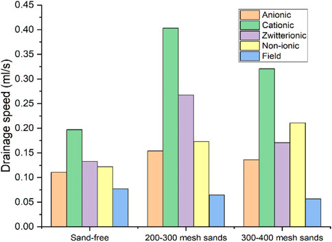
FIGURE 7. Drainage speeds under sand conditions.
Figure 8 shows that the average bubble area is inversely proportional to the number of bubbles; as time passes, the average bubble area increases; when the anionic foam drainage agent is used, the foam coalescence area in case of no sand existence is larger than that in case of sand existence, and the average bubble area decreases as the sand particle size increases; the average bubble area in case QH-X1 is used is smaller than that in case the anionic foam drainage agent is used, and the presence of 200–300-mesh sands increases the average bubble area.
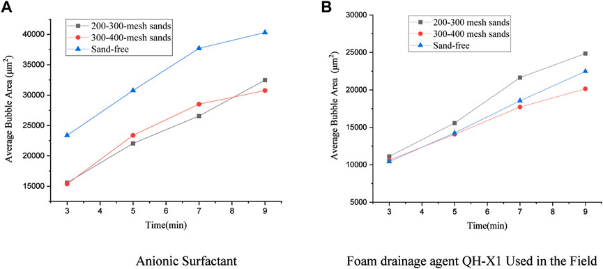
FIGURE 8. Average bubble area changes with time under different sand conditions.
The adsorption energy between sand and foam can affect the average bubble area, that is, the smaller the particle size of hydrophilic sand, the larger the specific surface area, the larger the adsorption energy between sand and foam, the more stable the foam, and the slower the drainage speed. In addition, the stronger the polarity of the foam drainage agent, the stronger its adsorption with hydrophilic sand, the more stable the foam, the smaller the change in bubble area. It can be seen that the average bubble area is determined by the type of foam drainage agent and the absorbability of sand.
(2) Bubble Wall Thickness
Figure 9 shows the bubble wall thickness changes with time. As time passes, the wall thicknesses of all the bubbles become gradually thin; in case of no sand existence, the bubble wall thickness of the anionic foam drainage agent significantly decreases (Figure 9A) and the bubble wall thickness reductions of the other foam drainage agents are gentle, while the bubble wall thicknesses become obviously thinner after sand existence, and in this case, they are increasingly thinner as the particle sizes increase and fluctuate slightly with time; as shown in Figure 9B, sands have two possible impacts on QH-X1, i.e., the bubble wall thickness is greater in case of containing 200–300-mesh sands and less in case of containing 300–400-mesh sands, and 5 minutes later, the wall thickness changes are not considerable in general.
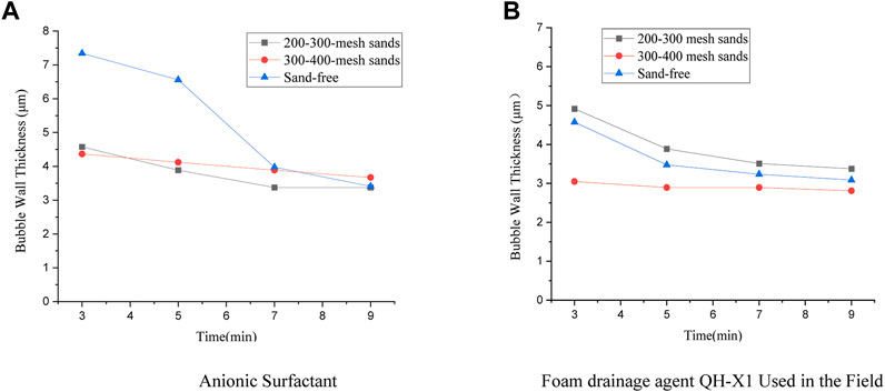
FIGURE 9. Bubble wall thickness changes with time under different sand conditions.
When adding sand with different mesh, the bubble wall thickness of different foam drainage agent varies, which mainly depends on the interaction mechanism between sand and foam drainage agent. Firstly, hydrophilic sand can slow down the drainage speed, increase the water flow resistance, and delay the foam thinning rate; Secondly, the foam disproportionation rate can be reduced, that is, the hydrophilic sand can be adsorbed on the gas-liquid interface to increase the thickness of the liquid film and reduce the contact area between the gas and liquid film. Finally, it can delay the bursting speed of the internal bubble, that is, the bubble is wrapped in sand, which can increase the stability of the bubble. Under external interference, the bubble is not easy to burst.
(3) Plateau Boundary
The Plateau foam structure balance rule regards four interacting bubbles as basic units. The particle size range of these bubbles is 10 μm-1 cm. Their intersection is called the node. The concave triangular cylinder extending outward from the node is the Plateau channel. The plane extending outward from each side edge in the plateau channel is a bubble liquid film. In this balance rule, every three bubbles constitute a plateau channel. The angle between any two channels is about 109.47°. Between every two bubbles occurs a liquid film. The angle between any two liquid films is about 120° (Kai and Zhou, 2021). See Figure 10. It can be seen in the figure that a basic bubble unit consists of one node, four plateau channels, and six liquid films.
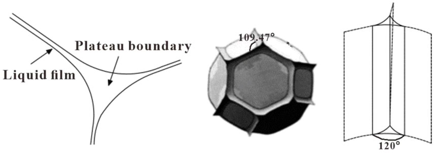
FIGURE 10. Basic structure of liquid foam and plateau interface with force balance (Kai and Zhou, 2021).
The Plateau interface with force balance is as shown in Figure 10. After bubbles are formed, seepage or drainage repeatedly occurs under gravity and capillary force. According to the Plateau law, we have:
PB and PA are the pressures at the points B and A; α is the curvature radius of the liquid channel; γ is the surface tension. When the pressure at the point B is higher than that at the point A, the liquid in the bubble flows from B to A under the pressure difference, thus causing the liquid film to be thinner and the bubbles to break and coalesce.
In case of sand existence, the Plateau boundary changes are as shown in Figure 11. In case of no sand existence, the cationic-type foam drainage agent’s Plateau boundary width dramatically decreases 5 minutes later, while in case of sand existence, the boundary shows a gentle change trend, and larger sand particle sizes means smaller channel width; whether sand existence occurs or not, the Plateau boundary of the field foam drainage agent QH-X1 changes gently with time, and 5 mins later, its channel width, unlike the scenario of using the anionic foam drainage agent, decreases as the particle sizes become smaller; the impact of sands on the Plateau boundary is a complicated solid-gas-liquid coupling process, so there are Plateau boundary differences between different foam drainage agents.
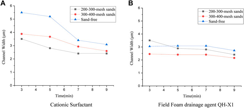
FIGURE 11. Plateau boundary change under different sand conditions.
A water-based foam system is an unbalanced system, whose structure constantly evolves with time. Its evolution process mainly involves three mechanisms: bubble seepage, liquid film breakup, and gas diffusion. Under the capillary pressure, the liquid-phase component in the bubble moves from the bubble liquid film into the Plateau channel, and then, under the gravity, the liquid in the foam system continues to seep downward along the Plateau channel, thus causing the thicknesses of the liquid films in the foam system to change continuously. When seepage occurs, the repulsive forces of the surface active agent molecules and the insufficient Marangoni effect lead to liquid film breakups, mainly at the dry foam stage. According to the Laplace’s law, a bubble with a small curvature radius has higher pressure and the gas therein diffuses through the liquid film into large bubbles under surface tension, thus reducing the area of the gas-liquid interface in the system. When the interactions of the three mechanisms above lead to seepage, the flows of the liquids existing in minute quantities in the liquid films affect gas diffusions between bubbles, and liquid film breakups and gas diffusions result in an increase in average bubble diameter, further promoting liquid seepage and causing liquid bubbles to show unbalancedness that continuously changes with time.
In addition, it can be seen from the above analysis that the micro parameter of Plateau boundary and macro parameter of foam half-life are closely related to the drainage speed. From the macro-perspective, the faster the drainage speed, the shorter the foam half-life, indicating the more obvious the trend of foam coalescence, the more unstable the foam. From the micro-perspective, the faster the drainage speed, the faster the seepage rate of liquid components from Plateau boundary, the faster the thickness of liquid film changes, and the worse the stability of foam. It can be seen that the drainage speed is the key parameter connecting the microscopic and macroscopic properties of the foam.
In short, there are three factors affecting the number of bubbles, drainage rate, and coalescence degree: 1) for QH-X1, hydrophilic particles can extend the liquid film stability time; 2) for ionic foam drainage agents, smaller hydrophilic particles mean larger specific surface area, higher sand-bubble absorption energy, more stable foam, and slower drainage rate; 3) there are obvious differences in average bubble area, bubble wall thickness, and Plateau boundary under different sand conditions, and for an anionic foam drainage agent, the average bubble area, bubble wall thickness, and Plateau channel width decrease after sands are included, more obviously in case of larger sand particle sizes. The study on the foam drainage agent used in the field shows that lower foam parameters generally correspond to smaller-size sand grains but the various parameters change differently before and after the sand existence.
The sand existence in field is composed mainly of quartz, illite, and illite/smectite mixed; And the main body is 200–400 mesh sized hydrophilic particles. Its impacts on the performances of the foam formed by Sodium Dodecyl Benzene Sulfonate (anionic type), Hexadecyl Trimethyl Ammonium Bromide (cationic type), Lauramido propyl Hydroxy Sulfobetaine (zwitterionic type), OP-10 (non-ionic type), and the field compound foam drainage agent QH-X1 has the following patterns and mechanisms:
(1) Particles form adsorption films in gas-liquid interfaces and laminar structures in thin inter-bubble liquid films, thus bringing about more stable bubble coalescence, disproportionation, and unloading. Thus, the hydrophilic inflow sands can improve the stiffness, half-life period, and comprehensive rating of the foam formed by the field compound foam drainage agent QH-X1.
(2) The bubbles change from wet state to dry state over time, the shape of each bubble changes from spherical shape to polyhedron; the number of bubbles gradually decreases, and the bubble coalescence phenomenon is increasingly more obvious. Bubble coalescence is related to drainage rate, i.e., higher drainage rate means that the foam is more unstable and the bubble coalescence trend is more obvious; on the contrary, lower drainage rate means that the foam formed by the foam drainage agent provides has higher stability.
(3) Smaller hydrophilic particles mean larger specific surface areas, higher adsorption energy levels between sand particles and bubbles formed by an ionic foam drainage agent, more stable foam, and slower drainage rate. The impacts of different foam drainage agent types on average bubble area, bubble wall thickness, and Plateau boundary are obviously different under different sand conditions. For anionic foam drainage agents, sand existence causes the average bubble area, bubble wall thickness, and Plateau channel width to decrease, more obviously if sand particle sizes are larger. For the field foam drainage agent QH-X1, the foam parameters are generally lower as sand particles are smaller, but their change trends after sands are included are different.
The original contributions presented in the study are included in the article/supplementary material, further inquiries can be directed to the corresponding authors.
NL, WJ and GC contributed to conception and design of the study. YJ organized the database. JY and RZ performed the statistical analysis. DF, RK and HW wrote the first draft of the manuscript. BP, FL, ZX, and QW wrote sections of the manuscript. All authors contributed to manuscript revision, read, and approved the submitted version.
NL, WJ, GC, HW, and QW were employed by RIPED. YJ and RZ were employed by the company PetroChina Zhejiang Oilfield Company. JY, BP, and FL were employed by PetroChina Yumen Oilfield Company. DF, ZX, RK were employed by PetroChina Qinghai Oilfield Company.
All claims expressed in this article are solely those of the authors and do not necessarily represent those of their affiliated organizations, or those of the publisher, the editors and the reviewers. Any product that may be evaluated in this article, or claim that may be made by its manufacturer, is not guaranteed or endorsed by the publisher.
Ata, S. (2012). Phenomena in the froth phase of flotation — a review. Int. J. Mineral Process. 102–103 (2), 1–12. doi:10.1016/j.minpro.2011.09.008
Dippenaar, A. (1982). The destabilization of froth by solids. II. The rate-determining step. Int. J. Mineral Process. 9 (1), 15–22. doi:10.1016/0301-7516(82)90003-5
Dippenaar, A. (1982). The destabilization of froth by solids. I. The mechanism of film rupture. Int. J. Mineral Process. 9 (1), 1–14. doi:10.1016/0301-7516(82)90002-3
Fameau, A. L., and Salonen, A. (2014). Effect of particles and aggregated structures on the foam stability and aging. Comptes Rendus Phys. 15 (8/9), 748–760. doi:10.1016/j.crhy.2014.09.009
Gareth, D. M., and Morris, J. (2014). Behaviour of a galena particle in a thin film, revisiting dippenaar. Int. J. Mineral Process. 131, 1–6. doi:10.1016/j.minpro.2014.07.004
Guo, D., Yang, X., and Sun, J. (2018). Research and application of efficient and economic draining and gas-recovery technique for water-producing natural gas well [J]. Mod. Chem. Ind. 38 (10), 37–139. doi:10.16606/j.cnki.issn0253-4320.2018.10.030
Honaker, R. Q., and Ozsever, A. V. (2003). Evaluation of the selective detachment process in flotation froth. Elsevier 16 (10), 975–982. doi:10.1016/s0892-6875(03)00266-8
Huang, Y., She, C. Y., Zhong, X. Y., and Duan, F. (2005). The recent situation and development tendency on the foreign technology of dewatering gas production. Drill. Prod. Technol. 04, 57–60.
Jiang, Y., Jovancicevic, V., and Ramachandran, S. (2007). Foam for gas well deliquification. Colloids Surfaces A Physicochem. Eng. Aspects 309 (1/3), 177–181. doi:10.1016/j.colsurfa.2006.10.011
Kai, J., and Zhou, Y. (2021). Analysis on microscopic properties of water-based foam system [J]. Liaoning Chem. Ind. 50 (12), 1840–1845.
Li, Z., Zhang, Q., and Huang, X. (2015). Research and application of foam drainage agent for drainage gas recovery of gas wells [J]. Sci. Technol. Vis. 25, 68–70. doi:10.19694/j.cnki.issn2095-2457.2015.25.048
Pandey, S., Bagwe, R. P., and Shah, D. O. (2003). Effect of counterions on surface and foaming properties of dodecyl sulfate. J. Colloid & Interface Sci. 267 (01), 160–166. doi:10.1016/j.jcis.2003.06.001
Qi, H., Bai, Z., Zhang, Q., and Lai, X. (2018). Synthesis of a Gemini betaine surfactant and its properties as foam drainage agent. Tenside Surfactants Deterg. Vol. 2 (55), PP142–147. doi:10.3139/113.110551
Qian, L. (2010). “Aqueous foam stabilized by short -chain amphiphiles/particles and surfactants/particles[D],” (Jinan: Shandong University). Doctoral Dissertation.
Qu, C., Liu, Z., and Yin, H. (2020). A new anti-condensate foam drainage agent for drainage gas recovery [J]. Acta Pet. Sin. 41 (7), 865–874. doi:10.7623/syxb202007008
Rahman, R. M., Ata, S., and Jameson, G. J. (2012). The effect of flotation variables on the recovery of different particle size fractions in the froth and the pulp. Int. J. Mineral Process. 106–109 (6), 70–77. doi:10.1016/j.minpro.2012.03.001
Solesa, M. (2006). “Production optimization challenges of gas wells with liquid loading problem using foam drainage agents [J],” in SPE Russian Oil and Gas Technical Conference and Exhibition, 12 - 15 Oct 2021.
Tao, D. (2005). Role of bubble size in flotation of coarse and fine particles—A review [J]. Sep. Sci. Technol. 39 (4), 741–760. doi:10.1081/SS-120028444
Van Nimwegen, A. T., Portela, L. M., and Henkes, R. A. W. M. (2015). The effect of surfactants on air–water annular and churn flow in vertical pipes. Part 1: Morphology of the air–water interface. Int. J. Multiph. Flow 71, 133–145. doi:10.1016/j.ijmultiphaseflow.2014.03.008
Wang, J., Nguyen, A. V., and Farrokhpay, S. (2016). A critical review of the growth, drainage and collapse of foams. Adv. Colloid Interface Sci. 228, 55–70. doi:10.1016/j.cis.2015.11.009
Wu, J., Zhang, R., and Jia, W. (2018). Efficient foam drainage agent based on Gemini surfactant and nanomaterials [J]. Chem. Res. Appl. 30 (2), 263–269.
Xiong, C., Cao, G., and Zhang, J. (2019). Nanoparticle foam drainage agents for major gas fields in China [J]. Petroleum Explor. Dev. 46 (5), 966–973. doi:10.11698/PED.2019.05.16
Xu, H. (2022). Research and application of oil resistance of a new compound foam drainage agent [J]. Fault-Block Oil Gas Field 29 (3), 422–426. doi:10.6056/dkyqt202203023
Yang, X., Yu, Z., and Xiao, S. (2013). Research on the law of liquid loading in downhole throttle gas well in sulige gasfield [J]. China Pet. Mach. 41 (09), 105–107.
Zhang, H., Wang, L., and Yanzhong, Z. (2021). Development and field application of salt-resistant, oil-resistant, and high-temperature resistant foam drainage agent in yan 113 gas field [J]. J. Yanan Univ. Nat. Sci. Ed. 40 (01), 51–54+60.
Keywords: sand existence, foam unloading agent, foam performance, half-life, comprehensive foam rate
Citation: Li N, Jiang W, Jiang Y, Yang J, Cao G, Zheng R, Feng D, Wang H, Xu Z, Peng B, Li F, Kang R and Wu Q (2023) Study into impacts of formation sands on foam performance during drainage gas production—Take Qinghai Oilfield’s Sebei Gasfield for example. Front. Earth Sci. 11:1180501. doi: 10.3389/feart.2023.1180501
Received: 06 March 2023; Accepted: 05 April 2023;
Published: 15 May 2023.
Edited by:
Jinxuan Han, Yanshan University, ChinaReviewed by:
Yonghui Liu, Southwest Petroleum University, ChinaCopyright © 2023 Li, Jiang, Jiang, Yang, Cao, Zheng, Feng, Wang, Xu, Peng, Li, Kang and Wu. This is an open-access article distributed under the terms of the Creative Commons Attribution License (CC BY). The use, distribution or reproduction in other forums is permitted, provided the original author(s) and the copyright owner(s) are credited and that the original publication in this journal is cited, in accordance with accepted academic practice. No use, distribution or reproduction is permitted which does not comply with these terms.
*Correspondence: Nan Li, bGluYW4xOEBwZXRyb2NoaW5hLmNvbS5jbg==; Qiubo Wu, d3VxaXVib0BjbnBjLmNvbS5jbg==
Disclaimer: All claims expressed in this article are solely those of the authors and do not necessarily represent those of their affiliated organizations, or those of the publisher, the editors and the reviewers. Any product that may be evaluated in this article or claim that may be made by its manufacturer is not guaranteed or endorsed by the publisher.
Research integrity at Frontiers
Learn more about the work of our research integrity team to safeguard the quality of each article we publish.