 Hongru Li
 Min Yang
 Xiaotao Yin
95% of researchers rate our articles as excellent or good
Learn more about the work of our research integrity team to safeguard the quality of each article we publish.
Find out more
ORIGINAL RESEARCH article
Front. Earth Sci. , 09 May 2023
Sec. Environmental Informatics and Remote Sensing
Volume 11 - 2023 | https://doi.org/10.3389/feart.2023.1178622
This article is part of the Research Topic Advances in Development and Utilization of Underground Space, volume II View all 13 articles
Gravity anchor blocks are a common type of ground anchor used for suspension bridges, whose bearing depends on its large body and gravity. As there is no stratum requirement, the safety of the anchor block is important for bridge stability. This study summarizes all available estimation indexes, calculating methods, and evaluation criteria for gravity anchor block safety for the Ruili bank of the Banjin Dam grand suspension bridge. The anti-overturning, anti-sliding, base stress, and deformation safeties were comprehensively evaluated using methods including the suggested specification method (SM), simplified mechanical method (SMM), and finite element method (FEM), the results of which were compared and analyzed. The reasons for errors and improved formulas and working conditions were presented. The main conclusions were as follows. 1) The methods for calculating different evaluation indexes according to specifications lack consistency. Moreover, FEM requires that designers have good computer skills and has low feasibility in practice. 2) The SMM for gravity anchor block safety estimation as described in this study, whose indexes cover systematic and overall, the computational formula is simple and speedy, with relatively conservative results and good practicability. 3) SM, SMM, and FEM were all used for the safety estimation of gravity anchor blocks in Ruili bank. The anti-overturning and anti-sliding stability coefficients must all meet the specification requirements of 2.0. SM cannot be used to estimate the base tensile stress under limited conditions. SMM denoted tensile stress at 2.5 times the main cable design force, compared to 3.2 P for FEM. Deformation calculation methods are not given by SM, but can be suggested by SMM based on the elastic mechanics. The horizontal displacements under design load conditions were 122 mm (SMM), 108 mm (FEM), and 44 mm (composite foundation treated by root piles), with a safety standard of <80 mm. The vertical displacements were 338 mm (SMM), 110 mm (FEM), and 123 mm (composite foundation treated by root piles), with a safety standard of <160 mm. These findings proved the feasibility of SMM for the safety design of gravity anchor blocks in cases lacking regional experience.
Gravity anchors are a traditional anchorage type used for both sea and land, including ground-anchored suspension bridges in areas with open terrain and general strata. With increasing construction of long-span suspension bridges, the contradiction between anchorage safety and environmental protection requirements has become increasingly prominent. The accurate evaluation of the safety of gravity anchors is an urgent challenge in the context of the goals of economy and environmental protection.
At present, safety evaluation indexes and methods of gravity anchorage are mainly based on the Design Specification for Highway Suspension Bridge (JTG/T D 65-05-2015) and the Specification for Design of Foundation of Highway Bridges and Culverts (JTG D63-2007). These indexes mainly consider anti-overturning and anti-sliding stability coefficients, maximum foundation stress, foundation bearing pressure, and deformation control standard determined by the main span. Research has mainly focused on safety evaluation. 1) The design of gravity anchorage mainly relies on the friction provided by the structure–foundation to resist sliding; thus, the friction test of concrete-foundation soil is the basic design parameter to ensure the safety of gravity anchorage (Ran et al., 2018; Tan et al., 2015, Ji et al., 2003; Liu et al., 2011; Liu et al., 2022a). 2) The indoor model test (Li et al., 2005; Li et al., 2018), field scale test (Li, 1995), and numerical experiment (Li et al., 2016; Huang et al., 2014; Liu et al., 2020) are used to determine whether the anti-sliding stability of gravity anchor-foundation, base stress, and deformation meet the design and specification requirements. 3) The parameters obtained from these investigations are inserted into the theoretical formula to estimate the evaluation indexes of the anchorage and evaluate its safety (Yin et al., 2017a; 2017b; Liu and Lin, 2014; Zhu, 2011; Liu, 1999; Liu et al., 2022b).
In this study, according to the specifications for suspension bridges and bridge culverts, the indexes, methods, and evaluation standard of safety evaluation of gravity anchors were systematically summarized. A corresponding simplified mechanical model of the anchorage was established based on the gravity anchor block project of the Ruili bank of the Banjin Dam suspension bridge. The safety of the anchorage was comprehensively evaluated using standard, simplified mechanical, and finite element methods. The physical and mechanical mechanisms of the mechanical model method were identified, and the differences improved. This study aimed to establish a simple and systematic safety evaluation method and index system for gravity anchors.
According to the provision of Article 8.4.1 for the Design Specification for Highway Suspension Bridge (JTG/T D 65-05-2015), the anti-overturning stability coefficient of the pier foundation is not less than 2.0.
According to the provisions of Article 4.4.1 for the Specification for Design of Foundation of Highway Bridges and Culverts (JTG D63-2007), the anti-overturning stability coefficient and eccentricity of the pier foundation are calculated according to the following formula:
where k0 is the anti-overturning stability coefficient of the pier foundation, s is the distance from the center of gravity of the section to the overturning axis (m), e0 is the eccentricity from the action point of the external force R to the center of gravity axis of the base (m), Pi is the vertical force (kN), ei is the arm of the vertical force to the center of gravity of the section (m), and hi is the arm of horizontal force to the center of gravity of the section (m).
According to the provision of Article 8.4.1 for the Design Specification for Highway Suspension Bridge (JTG/T D 65-05-2015), the anti-sliding stability coefficient of the pier foundation is not less than 1.6 in the construction stage and not less than 2.0 in the use phase.
According to the provisions of Article 4.4.2 for the Specification for Design of Foundation of Highway Bridges and Culverts (JTG D63-2007), the formula to calculate the anti-sliding stability coefficient of the pier foundation is as follows:
where ka is the anti-sliding safety factor of the pier foundation, ∑Pi is the sum of vertical force, ∑TiP is the sum of anti-sliding horizontal force, ∑Tia is the sum of sliding horizontal force, and μ is the friction coefficient between the base and foundation.
According to the provision of Article 8.4.2 for the Design Specification for Highway Suspension Bridge (JTG/T D 65-05-2015), tensile stress is not allowed in the anchorage base during construction and operation, and the maximum stress value satisfies the following formula:
where γR is the base resistance coefficient and is generally taken as 1.00 in the use stage and 1.25 in the construction stage, referring to Article 3.3.6 of the Specification for Design of Foundation of Highway Bridges and Culverts (JTG D63-2007), and [fa] is the allowable bearing capacity of subsoil, referring to Article 3.3 of the Specification for Design of Foundation of Highway Bridges and Culverts.
According to the provisions of Article 4.2 for the Specification for Design of Foundation of Highway Bridges and Culverts (JTG D63-2007), the bearing capacity of the foundation satisfies the following formula under the condition of uniaxial eccentric of foundation base:
where A is the base area (m2), M is the bending moment of horizontal force and vertical force on the center of gravity axis of the base (kN·m), W is the sectional resistance moment in the eccentric direction of the base, and the formula is BL2/6, where B is the transverse width and L is the axial length.
According to the provision of Article 8.4.1 for the Design Specification for Highway Suspension Bridge (JTG/T D 65-05-2015), the allowable horizontal deformation of the anchorage should not be greater than 0.0001 times the main span and the vertical displacement should not be greater than 0.0002 times the main span during the operation stage.
The super large suspension bridge anchorage for Banjin Dam is a single-span, double-hinged, steel truss girder, double-tower ground-anchored suspension bridge with a main span of 800 m. The Ruili and Menglian banks both contain embedded gravity anchorages. The foundation of Ruili bank is a loose, slightly dense gravel soil layer. The allowable bearing capacity of the foundation is 250 kPa, and the coefficient of friction on the basis is 0.40. The foundation of the Menglian bank is strongly weathered dolomite. The allowable bearing capacity of the foundation is 500 kPa, and the coefficient of friction on the basis is 0.45. The parameters of the rock soil mass and structural materials are shown in Table 1.
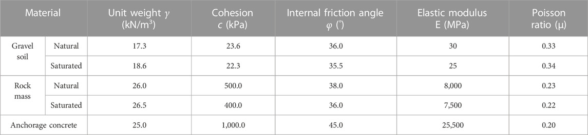
TABLE 1. Physical and mechanical parameters of rock soil mass and anchor materials in engineering.
The anchorage of Ruili bank is located on the top of a small hill. Most of the cover soil on the surface is adobe soil of the quaternary system. The soil thickness is 1.40–55.30 m by drilling. The underlying bedrock is limy dolomite of the Middle Triassic Hewanjie Formation with large thickness, which has good mechanical properties. Therefore, it can be used as the bearing strata for anchorage. After construction according to the anchorage design scheme, a temporary slope is formed around the anchorage foundation pit.
Taking the gravity anchor block in Ruili bank with relatively poor stability as an example, the sizes of the left and right anchor blocks are 71 m long × 25 m wide in the horizontal projection. The prestress is applied to the front and rear anchor surfaces at 377,788.7 kN, which is obtained according to the weight of a single abutment and anchor. The design diagram of the gravity anchor block on Ruili bank is shown in Figure 1.
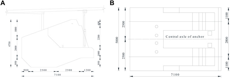
FIGURE 1. Design drawing of gravity anchor blocks in Ruili bank. (A) The vertical view of gravity anchor. (B) The cross section of gravity anchor.
The control elements of the safety evaluation of the gravity anchor block on Ruili bank are as follows:
(1) Structural safety index
The anti-sliding stability coefficient Ka of the gravity anchor block is >2.0 and the anti-overturning stability coefficient Kc is >2.0.
(2) Safety of the foundation bearing
The base stresses in the construction and operation stages must be less than the modified allowable bearing capacity of gravel soil foundation, with no tensile stress.
According to the safety evaluation standard for foundation bearings, taking the axis section of Ruili bank as an example, the excavation depth of abutment is approximately 25.0 m from the natural ground to the basement. The anchorage basement is approximately 35.0 m from the natural ground. According to the Specification for Design of Foundation of Highway Bridges and Culverts (JTG D63-2007), the correction coefficient of loose-slightly slightly dense gravelly soil is 50% of the correction coefficient of dense gravel soil; thus, k1 = 3.0/2.0 = 1.5 and k2 = 5.0/2.0 = 2.5. The natural unit weight γ1 of basal gravel soil is 17.3 kN/m3. The unit weight γ2 of backfilling soil is 16.3 kN/m3. The correction of the bearing capacity of the gravelly soil foundation is as follows:
where k1 and k2 are the correction coefficients of dense gravel soil; b and h are the width and depth of the foundation, respectively; and fa0 is the bearing capacity of the gravelly soil foundation.
The bearing capacity of the gravel soil with depth and width corrections of 1,354 kPa (abutment base) and 1,762 kPa (anchorage base) can be used to determine the bearing safety of the gravel soil foundation under the condition that considers depth and width correction.
(3) Deformation stability
The allowable horizontal deformation of the anchorage should not be greater than 0.0001 times the main span, while the horizontal deformation should not be >80 mm. The vertical deformation should not be greater than 0.0002 times the main span, while the vertical deformation of this project is not >160 mm.
The coordinate system 0 point of the simplified mechanical model is the geometric center of the horizontal projection of the bottom surface. The weight of the anchorage G is approximately 1,072,207.0 kN, and its action point coordinates are (−2.5, 0.0). The design load P of a single cable is 214,000.0 kN. The horizontal angle at the top of the cable abutment is 22.23°, with action point coordinates of (14.2, 34.0). The pile load of the approach bridge P20 is 9,777.0 kN, with action point coordinates of (−14.8, 0.0). The pile load of the approach bridge P21 is 24,334.0 kN, with action point coordinates of (26.7, 0.0). The simplified diagram of forces acting on the gravity anchor blocks on the Ruili bank is shown in Figure 2.
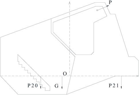
FIGURE 2. Simplified diagram of forces acting on gravity anchor blocks on Ruili bank.
The forces and their parameters in Figure 2 are inserted into Formula 1, Formula 2, Formula 3, Formula 4, Formula 5, Formula 6. The anti-sliding stability coefficient, anti-overturning stability coefficient, and base stress of the anchorage structure are listed in Table 2. The foundation force analysis is simplified, as shown in Figure 3. The forces and their parameters in Figure 3 are inserted into Formula 8 of the elastic mechanical shear strain and Formula 9 of the compression deformation to simply estimate the horizontal displacement and vertical displacement of the foundation. The calculated displacement is smaller than the actual displacement. The safety estimation results of the gravity anchor blocks on Ruili bank based on simplified mechanical models are shown in Table 2. The thickness of gravel soil is 30.0 m.
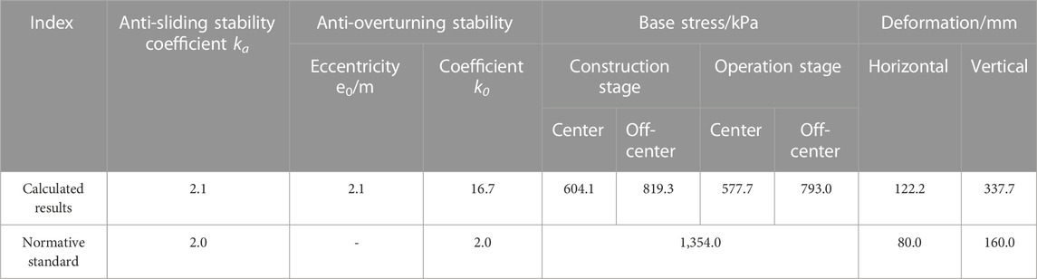
TABLE 2. Safety estimation results of the gravity anchor blocks on Ruili bank based on simplified mechanical models.
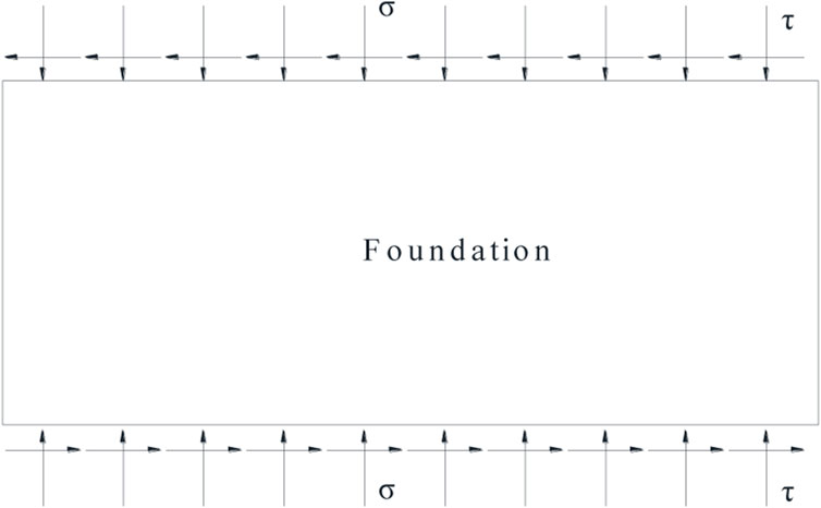
FIGURE 3. Simplified diagram of forces acting on the gravelly soil foundation on Ruili bank.
The calculation of anti-sliding and anti-overturning stability coefficients considers the weight of anchorage, the pile load of the approach bridge, and the cable force in Table 2. The calculation of the base stress only considers the weight of the anchorage in the construction stage, while the calculation of the eccentric bending moment considers all the forces. The calculation of the base stress and eccentric bending moment considers all the forces in the operation stage. Table 2 shows that the anti-overturning stability of the Ruili bank calculated using the simplified mechanical model meets the normative standard. The anti-sliding stability also meets the normative standard. The average and maximum stresses of the base stress are less than the bearing capacity of foundation gravel soil with depth and width correction in the construction and operation stages, and the bearing capacity of the gravel soil foundation is safe. The horizontal and vertical deformations of the anchorage-foundation do not meet the deformation stability standard.
According to the terrain survey and anchorage design data, the numerical model size was 200 m from the foundation boundary along the x and y directions respectively, and the z direction is 200 m down from the bottom of the foundation based on the Abaqus calculation software. The numerical model of Ruili bank is shown in Figure 4.
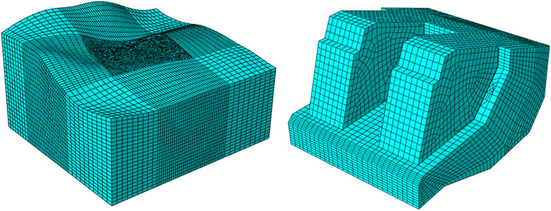
FIGURE 4. Numerical model of the Ruili bank.
The numerical model was divided into 170,901 elements and 233,400 nodes. The calculation adopted an elastic–plastic constitutive. The calculation parameters are shown in Table 1. The model was surrounded by normal constraints and the bottom was fully constrained.
The simulation of the construction process mainly comprised two parts. 1) The numerical loading test at the full design load, which is the initial geo-stress balance, followed by the excavation of 1–4 layers of soil, application of the anchor and prestress, application of the full large design load, and foundation pit backfill. 2) The numerical overload test, which continues loading at the full design load test until the tensile stress, connectivity of plastic zone, or 20 times the design load appears on the base.
To evaluate the bearing safety characteristics of gravel soil under the design load, the vertical stress of a single anchor base along the bridge direction axis under natural and saturated parameters is extracted and organized, as shown in Figure 5.
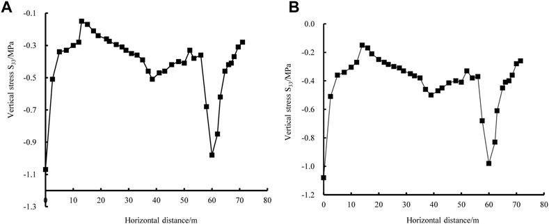
FIGURE 5. Vertical stress curve of the Ruili bank base floor under the one-time design load condition. (A) The vertical stress in the natural state. (B) The vertical stress in saturated state.
Figure 5 shows that the maximum at the toe of the abutment is 1,072 kPa, which is less than the bearing capacity of foundation gravel soil with a depth and width correction of 1,354 kPa (abutment base) in the natural state. The maximum postmedian anchorage is 970 kPa, which is less than the bearing capacity of foundation gravel soil with a depth and width correction of 1,762 kPa (anchorage base). The maximum at the toe of the abutment is 1,036 kPa, which is less than the bearing capacity of foundation gravel soil with depth and width correction of 1,354 kPa (anchorage base) in the saturated state. The maximum postmedian anchorage is 988 kPa, which is less than the bearing capacity of foundation gravel soil with a depth and width correction of 1,762 kPa (anchorage base). Therefore, the bearing capacity of the foundation gravel soil is safe.
To evaluate the corner dislocation characteristics of the anchorage structure under the design load, the displacement calculation results of the anchorage structure under the final force of the foundation pit excavation, anchorage construction completion, cable hanging, prestress application, backfill foundation pit, and normal use are shown in Figure 6. The maximum and minimum displacements of the Ruili bank anchor at the full design load are shown in Table 3.
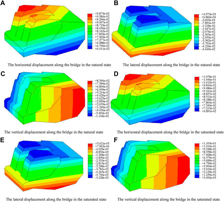
FIGURE 6. Displacement contours of Ruili bank anchors under the one-time design load condition.

TABLE 3. Maximum and minimum displacement of Ruili bank anchors under the one-time design load condition.
According to Figure 6 and Table 3, the maximum horizontal displacement along the bridge appears at the top of the abutment, which is 98.7–107.8 mm. The lateral displacement appears on both sides of the top of the abutment, with a maximum displacement of 5.0–52.3 mm. The maximum vertical displacement appears at the top of the abutment, with a maximum settlement of 11.4–110.3 mm. The maximum horizontal displacement of the anchorage structure is 107.8 mm, which is greater than 80.0 mm; thus, it does not meet the safety standard for horizontal displacement of the structure. The maximum vertical displacement of the anchorage structure is 110.3 mm, less than 160.0 mm, which meets the safety standard for the vertical displacement of the structure.
The normal and tangential forces of the anchorage base are, respectively, used by surface integral and multiplied by the designed concrete-gravel soil friction coefficient of 0.40 to obtain the anti-sliding force. The safety factor against sliding is calculated as follows:
Natural state:
Saturated state:
The anti-sliding stability coefficient of the gravity anchorage of the Ruili bank is 2.05 in the natural state and the anti-sliding stability coefficient is 2.04 in the saturated state under the full design load, which are both greater than the 2.00 in the specification, thus meeting the requirements for anti-sliding stability.
(1) Determination of the ultimate bearing capacity of the anchorage-foundation system
The monitoring point diagram is shown in Figure 7. The ultimate bearing capacity of the anchorage-foundation system was determined by the P–S curve of the load test. The displacement and loading amounts of the different geometric corners of the anchorage structure are drawn in the load–settlement curve as shown in Figure 8. The ultimate bearing capacity at the inflection point of the curve is 3.20 P overload in the natural state and 3.15 P overload in the saturated state, where P is the design load.
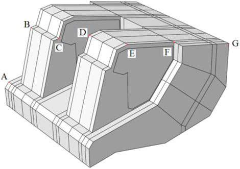
FIGURE 7. Monitoring point diagram.
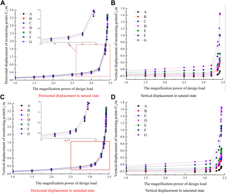
FIGURE 8. Load-settlement curve of the monitoring point of the anchorage under overload on Ruili bank.
The connectivity of the plastic zone was taken as a diagnostic criterion for system instability. The plastic zone cloud diagram on the anchorage-foundation axis section under the overload test is shown in Figure 9. Figure 9 and Table 4 show that the plastic zone is connected at a load of 3.20–3.75 P, and that the maximum plastic strain is multiplied in the natural state. The plastic zone is connected at the load of 3.15 P–3.30 P, and plastic strain increased dramatically in the saturated state. The ultimate bearing capacity obtained by plastic strain is 3.20 P load in the natural state and 3.15 P load in the saturated state.
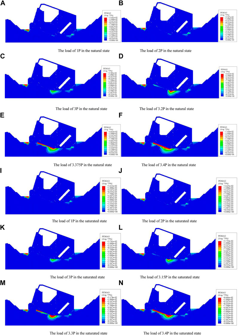
FIGURE 9. Plastic zone cloud diagram of the anchorage axis section of the Ruili bank under overload conditions.
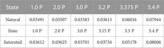
TABLE 4. Maximum equivalent plastic strain of the Ruili bank under overload conditions.
As an important index of safety evaluation of gravity anchors, the vertical stress of the basement axis under overload is shown in Figure 10. Figure 10 shows that most of the base stress is tensile stress under the action of 3.20 P overloading in the natural state. The maximum vertical stress of the abutment base is 1.07 MPa under the action of 1 P overloading, 1.38 MPa under 1.5 P overloading, 1.43 MPa under 2.0 P overloading, and 1.73 MPa under 2.5 P overloading. Most of the base stress is tensile stress under the action of 3.15 P overloading in the natural state. The maximum vertical stress of the abutment base is 1.04 MPa under the action of 1 P overloading, 1.52 MPa under 1.5 P overloading, 1.69 MPa under 2.0 P overloading, and 1.84 MPa under 2.5 P overloading. The allowable bearing capacity of the gravel soil foundation with modified abutment depth and width is 1,354 kPa. The ultimate overload of the foundation with the maximum stress value of 1,450 kPa exceeding the bearing capacity of 1,354 kPa is 3.5 P, which is larger than the overload of 1.5 P revealed by the finite element based on the bearing capacity. Through the specification calculation, the ultimate overload of the maximum base exceeding the foundation bearing capacity of 1,354 kPa is 3.5 P, which is larger than the load of 1.5 P obtained by the finite element based on the bearing capacity.
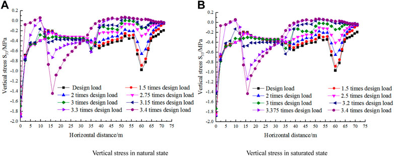
FIGURE 10. Vertical stress curves of the Ruili bank base floor under overload conditions.
The ultimate bearing capacities of the anchor rock systems in the Ruili bank are 3.20 P in the natural state and 3.15 P in the saturation state. When the bearing capacity is less than the critical value, the structure is safe, and the base tensile stress zone can be controlled. According to Formula 6, the tensile stress zone appears on the substrate when the load is 2.0–2.5 P, which is smaller than the finite element results.
(2) Safety evaluation of the gravity anchor block in the limit state
The maximum vertical stress appears at the toe of the abutment, which is also the maximum stress position under eccentric action. When the load exceeds 1.5 P, the maximum vertical stress is greater than the bearing capacity of foundation gravel soil with a depth and width correction, and the remaining parts are safe. The displacement cloud diagram along the bridge anchor of the Ruili bank in the limit state is shown in Figure 11. The maximum and minimum displacements of the anchors of Ruili bank in the limit state are shown in Table 5.
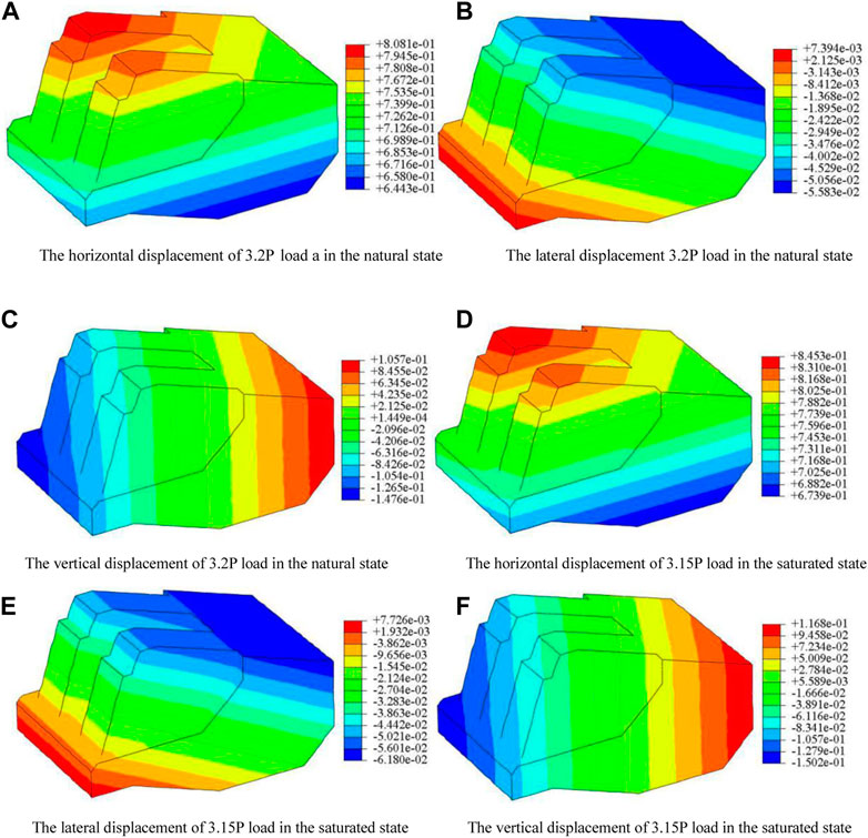
FIGURE 11. Displacement cloud diagram along the bridge of anchor of Ruili bank in the limit state.
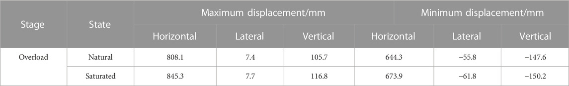
TABLE 5. Maximum and minimum displacement of anchors in Ruili bank in the limit state.
Figure 11 and Table 5 show a maximum horizontal displacement of the anchorage structure along the bridge of 845.3 mm at the top of the abutment in the limit state, which is >80.0 mm; thus, it does not meet the safety standard for the horizontal displacement of the structure. The lateral displacement occurs on both sides of the top of the abutment, with a maximum displacement of 61.8 mm. The maximum vertical displacement was 150.2 mm at the top of the abutment. This value was <160.0 mm, which met the safety standard for vertical displacement of the structure.
The failure mode of the stepped gravity anchorages is shown in Figure 12. The anchorage base is friction bearing. The abutment base is the stepped shear bearing, which differs from the friction bearing alone considered in the traditional design.
where
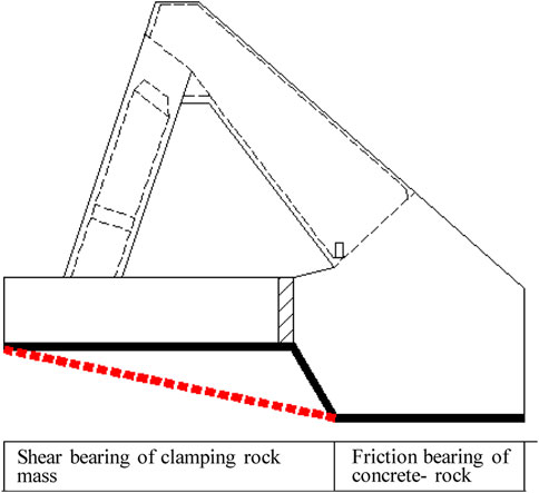
FIGURE 12. Failure mode of gravity anchor-foundation.
After excavation of the anchorage foundation, it is generally backfilled, which causes the upper part of the valve base of the abutment to cover the backfill soil to a certain thickness. The effective weight of the backfill soil
The anti-sliding stability coefficient calculated by the formula method was relatively large, while the finite element result was relatively small as the base stress was only larger in the local part, and most parts were less than the average stress. The stress distribution obtained by the finite element method was closer to the real situation. This demonstrated the need to distinguish the safety standards of the two methods.
The deformation results obtained by finite element calculation were smaller than those calculated by simplified Formula 8, Formula 9. This difference may be attributed to the fact that the simplified formula did not consider the lateral restraint of the foundation. The formula method can be used as a valuation method for preliminary design and lack of regional experience. The finite element method can be used as a valuation method in the construction organization design stage.
The structural deformation of the gravel soil foundation of the Ruili bank did not meet the safety control standards; thus, foundation reinforcement is required. The composite foundation treatment method mainly aims to improve the density and overall stiffness of the gravel soil. Considering the uneven distribution of the gravel soil layer and the borehole wall stability of the gravel soil in the construction stage, the root pile should be used for foundation reinforcement. The concrete construction method should be determined according to the on-site situation.
Assuming root pile diameter D of 0.3 mm, the pile is arranged in a square, with a pile spacing twice the pile diameter of 0.60 m fcu which is generally taken as the average value of cubic compressive strength of the indoor reinforced soil standard test block following the standard 90 days of curing, which is considered 3.0 MPa. Ep is generally preferred 100–200fcu, which is considered 100fcu.
The aforementioned parameters are based on experience, and the specific calculation parameters of the project are based on actual construction. By inserting the modulus of the composite foundation into Formula 8, Formula 9, the horizontal displacement was 44.4 mm (< 80.0 mm), and the vertical deformation was 122.8 mm (<160.0 mm). The bearing capacity and deformation of the gravel soil foundation after composite foundation treatment met the requirements.
The use of the aforementioned improved simplified formula methods conveniently allowed the comprehensive and systematic evaluation of anti-sliding stability and anti-overturning stability coefficients of gravity anchors, in addition to base stress checks, foundation bearing capacity, and deformation stability.
This study established a corresponding simplified mechanical model of anchorage based on the gravity anchor block project of the Ruili bank of the Banjin Dam suspension bridge. The safety of the anchorage was comprehensively evaluated using the standard method, simplified mechanical model, and finite element method, with the following conclusions:
1) The specifications comprehensively stipulated all aspects of the safety evaluation of the gravity anchors (anti-overturning stability, anti-sliding stability, foundation bearing safety, and deformation stability) but inconsistent calculation methods and models were applied for each index, especially for horizontal deformation. The evaluation of horizontal deformation only recommends the finite element method; however, the operability of the method is greatly limited.
2) The calculation and evaluation methods of anti-overturning stability, anti-sliding stability, base stress control, and deformation stability were established based on the simplified mechanical model according to the original formula of the specification. Compared with the finite element calculation results, the anti-overturning stability coefficient, anti-sliding stability coefficient, horizontal displacement, and vertical displacement obtained by the simplified mechanical model were larger than those of the finite element calculation results, and the maximum and minimum stresses to the foundation were smaller.
3) The improved gravity anchor block safety evaluation index for the physical and mechanical mechanisms was clear, and the calculation was fast. This formula method can be used for the valuation of gravity anchors during preliminary design and in cases lacking regional experience, or as a supplementary benchmark for the finite element method.
The original contributions presented in the study are included in the article/supplementary material. Further inquiries can be directed to the corresponding author.
HL provided overall guidance on the article and wrote this paper. MY and XY modified the article language.
This work was supported by the Loess Soil Mechanics and Engineering Key Laboratory of Shaanxi Province Foundation (13JS073) and the Natural Science Foundation of Shaanxi Province (2017JM5059).
The authors declare that the research was conducted in the absence of any commercial or financial relationships that could be construed as a potential conflict of interest.
All claims expressed in this article are solely those of the authors and do not necessarily represent those of their affiliated organizations, or those of the publisher, the editors, and the reviewers. Any product that may be evaluated in this article, or claim that may be made by its manufacturer, is not guaranteed or endorsed by the publisher.
Guo, X., Yu, M., Xinze, W., Xue, D. Y., and Han, H. X. (2022). Four new species of Ditrigona Moore (Lepidoptera, Drepanidae) in China and an annotated catalogue. J. Railw. Eng. Soc. 1091 (11), 57–98. doi:10.3897/zookeys.1091.78986
Huang, N., Li, Y., Cheng, L., Sun, G., and Wang, Z. (2014). Stability calculation and numerical analysis on anchorage of suspension bridge with gravity concrete. J. Henan Univ. Urban Constr., 23(3):5–8. doi:10.14140/j.cnki.hncjxb.2014.03.022
Ji, L., Xu, F., and Wang, B. T. (2003). Testing study on base resistance of the anchors at Runyang bridge. Chin. J. Rock Mech. Eng. 23 (2), 256–260.
Li, H., Huang, S., Wang, X., Li, S., and Xu, B. (2016). Finite element analysis on horizontal bear capacity characteristic ofgravity anchor. China Harb. Eng. 36 (1), 6–9.
Li, J., Zhang, Z., Huang, H., and Li, Y. (2005). Research on similarity model test of anchorage of qingfeng suspension bridge in ningbo. J. Tongji Univ. Nat. Sci. 33 (8), 1011–1016.
Li, S., Zhu, X., Li, H., Huang, S., Wang, X., Hou, Q., et al. (2018). Study design and baseline characteristics of inpatients with diabetes mellitus in a tertiary hospital in China: A database study based on electronic medical records. China offshore oil gas 30 (2), 152–157. doi:10.1111/jebm.12291
Li, Y., Lu, Z., Burbank, D. E., Kutish, G. F., Rock, D. L., and Van Etten, J. L. (1995). Analysis of 43 kb of the chlorella virus PBCV-1 330-kb genome: Map positions 45 to 88. J. Tongji Univ. Nat. Sci. 20 (20), 134–150. doi:10.1006/viro.1995.1462
Liu, N., Ning, L., Li, G., Song, Z., and Wang, S. (2022a). Method for evaluating the equivalent thermal conductivity of a freezing rock mass containing systematic fractures. Rock Mech. Rock Eng. 55, 7333–7355. doi:10.1007/s00603-022-03038-9
Liu, N., Ning, L., Wang, S., Li, G., and Song, Z. (2022b). A fully coupled thermo-hydro-mechanical model for fractured rock masses in cold regions. Cold Regions Sci. Technol. 205, 103707. doi:10.1016/j.coldregions.2022.103707
Liu, N., Ning, L., Xu, C., Li, G., Song, Z., and Yang, M. (2020). Mechanism of secondary lining cracking and its simulation for the dugongling tunnel. Rock Mech. Rock Eng. 53, 4539–4558. doi:10.1007/s00603-020-02183-3
Liu, W., and Lin, Z. (2014). Test study on the friction resistance of the north concrete anchor of qingcaobei yangtze river bridge. Highway 10, 124–128.
Liu, Y., Jun, F., Li, X., Gong, Z., and Chen, H. (2022c). Bearing mechanism of new type combined gravity anchor of suspension bridge. Chin. J. Undergr. Space Eng. 18 (S1), 187–193.
Liu, Y., Zhao, M., and Zheng, S. (2011). Test study on the friction resistance of the north concrete anchor of qingcaobei yangtze river bridge. J. Chongqing Normal Univ. Nat. Sci. Ed. (5), 911–915.
Ran, T., Mao, J. N., Mei, S. H., Wang, W. W., and Tan, L. H. (2018). Sensitivity analysis of rock-soil parameters of a gravity anchor excavation based on orthogonal experiment method. J. Yangtze River Sci. Res. Inst. 35 (2), 101–106. doi:10.11988/ckyyb.20160804
Tan, X., Xu, H., and Peng, W. (2015). The test and calculating method for gravity anchorage’s frictional coefficient of suspension bridge. Chin. J. Undergr. Space Eng. 11 (2), 549–552+584.
Yin, X., Fei, Y., Zhou, L., Wang, D., and Deng, Q. (2017a). Exploration on the horizontal limit bearing capacity formula of gravity anchorage. J. Railw. Eng. Soc. (1), 41–46.
Yin, X., Fei, Y., Zhou, L., Wang, D., and Deng, Q. (2017b). Joint bearing mechanism of structure and foundation for gravity anchor blockblock of suspension bridge. J. Traffic Transp. Eng. 17 (2), 1–11.
Keywords: gravity anchor block, anti-overturning stability coefficient, anti-sliding stability coefficient, base stress, ground bearing capacity, deformation stability
Citation: Li H, Yang M and Yin X (2023) Study on safety assessment methods of gravity anchors based on a simplified mechanical model. Front. Earth Sci. 11:1178622. doi: 10.3389/feart.2023.1178622
Received: 03 March 2023; Accepted: 04 April 2023;
Published: 09 May 2023.
Edited by:
Naifei Liu, Xi’an University of Architecture and Technology, ChinaReviewed by:
Ning Li, Xi’an University of Architecture and Technology, ChinaCopyright © 2023 Li, Yang and Yin. This is an open-access article distributed under the terms of the Creative Commons Attribution License (CC BY). The use, distribution or reproduction in other forums is permitted, provided the original author(s) and the copyright owner(s) are credited and that the original publication in this journal is cited, in accordance with accepted academic practice. No use, distribution or reproduction is permitted which does not comply with these terms.
*Correspondence: Min Yang, eWFuZ21pbjAwNjlAMTI2LmNvbQ==
Disclaimer: All claims expressed in this article are solely those of the authors and do not necessarily represent those of their affiliated organizations, or those of the publisher, the editors and the reviewers. Any product that may be evaluated in this article or claim that may be made by its manufacturer is not guaranteed or endorsed by the publisher.
Research integrity at Frontiers
Learn more about the work of our research integrity team to safeguard the quality of each article we publish.