
95% of researchers rate our articles as excellent or good
Learn more about the work of our research integrity team to safeguard the quality of each article we publish.
Find out more
ORIGINAL RESEARCH article
Front. Earth Sci. , 13 April 2023
Sec. Environmental Informatics and Remote Sensing
Volume 11 - 2023 | https://doi.org/10.3389/feart.2023.1169712
This article is part of the Research Topic Coal and Rock Dynamic Disasters: Advances of Physical and Numerical Simulation in Monitoring, Early Warning, and Prevention View all 15 articles
 Yonghao Zhang1
 Jianbin Zhao1Zhanshan Xiao1Yanwu Gao1Shitao Cui1Daojie Cheng1
 Mingming He2*Chaoqiang Fang1Haifang Xue3Ying Zhao4
During the drilling process, high-strength rock can lead to various issues such as drilling suppression, bit wear, and increased operational costs. To ensure safe and efficient drilling operations, it is crucial to accurately predict the strength parameters of the rock and recommend modifications to operational procedures. This paper proposes a low-cost and fast measurement method for predicting the strength parameters of rock in the field. To evaluate the effectiveness of this method, a drilling process monitoring experiment was conducted on sandstone, limestone, and granite. The experiment studied the effect of confining pressure on the response of cutting with an impregnated diamond bit. By analyzing the relationship between the thrust force, torque force, and penetration depth under different confining pressures, the researchers developed an analytical model for drilling that considers confining pressure, compressed crushed zone, and bit geometry. The results show that the confining pressure has a significant effect on the cutting response. As the confining pressure increases, the thrust force, torque force, and penetration depth at the cutting point also increase. Furthermore, a new measurement method was proposed to determine the strength parameters, such as cohesion, internal friction angle, and unconfined compressive strength. The estimated strength parameters for the three rock types using the drilling method were in good agreement with those of the standard laboratory test, with an error range of 10%. This method of estimating rock strength parameters is a practical tool for engineers. It can continuously and quickly obtain the drilling parameters of in-situ rocks.
The projected economic growth is expected to drive global energy demands to reach 20,679 million tons of oil equivalent by 2040, with 28% coming from oil and 23% from natural gas (Chong et al., 2016; Yang et al., 2019). The supply of the global energy market is heavily influenced by hydrocarbon resources, and the development of drilling technology has enabled deeper hydrocarbon resources to be explored to meet the growing energy demand worldwide (Li et al., 2016; Vedachalam et al., 2016). However, as boreholes become deeper, drilling efficiency tends to decrease, posing significant challenges that need to be addressed to promote drilling efficiency. The mechanical properties of the rock, such as strength parameters, significantly affect drilling efficiency, and high-strength rock during the drilling process can lead to drilling suppression, drilling bit wear, and high operational costs. To avoid such adverse effects, accurately predicting the strength parameters of rock during the drilling process and recommending effective modifications to operational procedures are essential for maintaining safer and more efficient drilling operations.
The unconfined compressive strength (UCS) test, which requires well-prepared samples, is time-consuming, costly, and a destructive procedure, making it challenging to determine the strength parameters of rock in the field (Kalantari et al., 2018). To overcome these limitations, indirect methods such as the point load test, scratch test, Schmidt hammer test, and block punch test have been developed for UCS determination (Palassi and Emami, 2014; Naeimipour et al., 2018). However, these methods have some limitations when it comes to evaluating the complex field conditions and related effects on field rock (Palassi and Emami, 2014). They provide only limited information about rock and may not accurately reflect the properties of field rock (Richard et al., 2012). In recent years, drilling has emerged as a promising technique for measuring rock strength parameters in the field. This method allows for fast and continuous measurement of field rock strength during the drilling process. Moreover, it is applied as a quasi-nondestructive field method and easily facilitated because of non-sampling and simple movement (Kalantari et al., 2018). Researchers have developed several methods for estimating rock strength based on forces limit equilibrium and energy equilibrium (Merchant, 1945; Evans, 1962; Nishimatsu, 1972; Roxborough and Philips, 1975; Nakajima and Kinoshita, 1979; Hoover and Middleton, 1981; Detournay and Defourny, 1992; Wojtanowicz and Kuru, 1993; Gerbaud et al., 2006; Franca, 2010; Hareland, 2010; Chiaia et al., 2013). However, except for Nakajima and Kinoshita’s model and Gerbaud’ model, the crushed zone has not been considered in the proposed relations between the drilling data and rock strength. To address this issue, Kalantari et al. (2018) developed an analytical model to estimate rock strength parameters using a T-shaped drag bit. Several other researchers (Karasawa et al., 2002a; b; Ohno et al., 2004; Bingham, 1964; Wolcott and Bordelon, 1993; Hoberock and Bratcher, 1996; Burgess and Less, 1985; Pessier and Fear, 1992; Warren, 1987; Lia and Itakura, 2012) have used various approaches to determine the UCS of rock during the drilling process based on the specific energy by Teale (1965). Analytical models based on energy equilibrium can easily resolve the problem of the crushed zone during the drilling process. However, the explicit relationship between the confining pressure and the response of drilling in the field has not been well-established, particularly in the deep rock mass.
In this study, an experiment was conducted to monitor the drilling process of sandstone, limestone, and granite, in order to investigate how the confining pressure affects the response of cutting with an impregnated diamond bit. The relationships between thrust force, torque force, and penetration depth were analyzed for different confining pressures. An analytical model was developed to take into account the effects of gravity, the compressed crushed zone, and the bit geometry on drilling. Furthermore, an advanced method was proposed to predict the cohesion, internal friction angle, and unconfined compressive strength of sandstone, limestone, and granite. The resulting unconfined compressive strength values obtained from the proposed method were compared with test results obtained in the laboratory.
During the drilling process monitoring, the bottom of drilling hole is affected by the confining pressure and fluid column pressure in the drilling hole as well as the applied force of the bit. In the drilling process, due to the continuous downward and forward movements of diamond particle in impregnated diamond bit, the crushed zone in front of the diamond particle is formed as shown in Figure 1A. For a diamond particle, assume that the diamond particle is a pentahedron as shown in Figure 1B. When the rock on both sides of the diamond particle occurs shear failure, the geometry and mechanism of the acting force of bit is shown in Figure 1. In the failure surface, the shear stress and normal stress caused by the ground stress, pore pressure and fluid column pressure can be expressed as
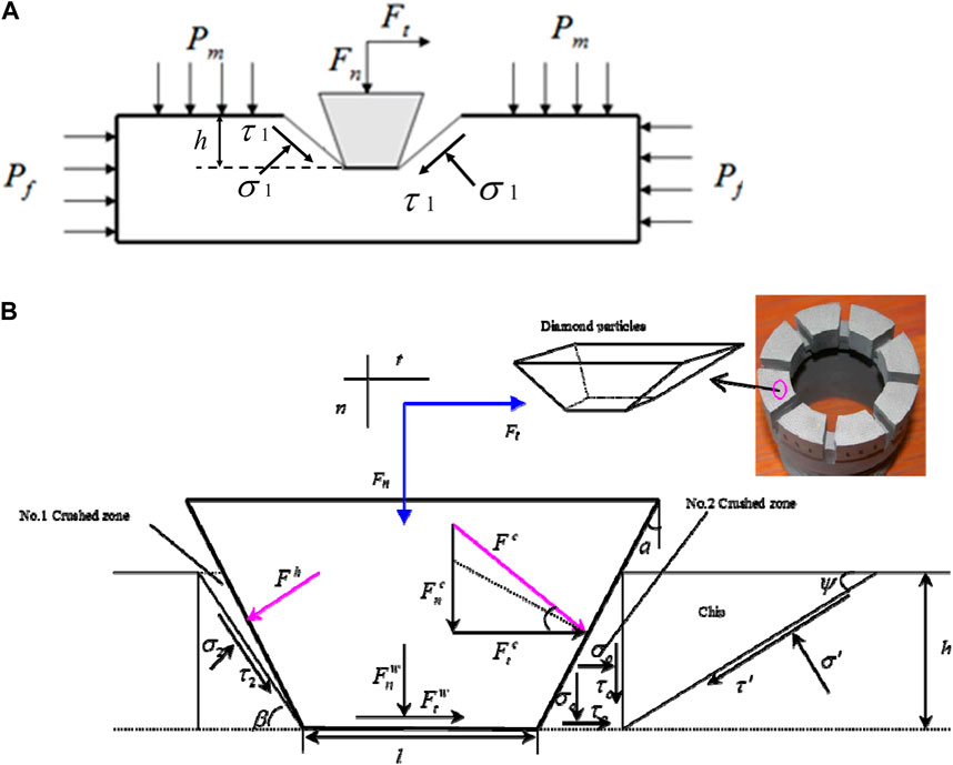
FIGURE 1. The bottom of drilling hole stress analysis (A) and geometry and mechanism of the acting forces in the proposed analytical model (B).
Where β is the angle of shear plane in the back of the blade, Pf is the confining pressure, Pm is the fluid column pressure in the drilling hole.
Generally, the drilling rotary process of rock is performed through two stages: penetration and cutting (Kalantari et al., 2018). The penetration and cutting stages are required to perform and occur simultaneously in the continuous process. In Figure 1B, each of the tangential forces Ft and normal force Fn has some components including the cutting force, the frictional force, and the normal force in the back end of diamond particle:
Where Fcn is the normal components of the cutting force, Fct is tangential components of the cutting force, Fnw is the normal components of the friction force, Ftw is the tangential components of the friction force in the front end of diamond particle, respectively, Fh is a normal force in the back end of diamond particle, Fh sina is the frictional force between the diamond particle and rock sides. The relationships among these parameters can be expressed as
Now, for the normal force in the back end of diamond particle ignoring the friction force between the back end of diamond particle and compressed crushed zone (No.1 crushed zone, see Figure 1B, the normal stress and shear stress in the fracture surface can be calculated as
Where A refers to the vertical cross-sectional area of the cut, σ2 and τ2 are normal stress and shear stress, respectively. Considering the real stress characteristics of rock at the bottom of drilling core, the total normal stress and total shear stress in the fracture surface can be calculated as
The Mohr-Coulomb failure criterion of rock can be given as
where C is the cohesion of intact rock, φ is the internal friction angle of intact rock. According to Eqs 1, 2, 10–14 then we have
If τ-σtanφ is replaced with the cohesion C in Eq. 14, and after some algebraic manipulation in Eq. 15, the normal force Fh in the back end of diamond particle can be calculated as
To obtain the minimum value of Fh, the value of β can be calculated as
The minimum value of Fh can be calculated as
Now, considering the No. 2 crushed zone (see Figure 1B), the tangential and normal components of the cutting force can be calculated as
After some algebraic manipulation, the shear strength τ0 and hydrostatic pressure σ0 in the No. 2 crushed zone can be obtained from Eqs 20, 21:
Shear tractions, τ’, and normal tractions, σ’, can be calculated as
ψ is the angle of the cutting plane in front of the blade. Considering the real stress characteristics of rock at the bottom of drilling core, the total normal stress and total shear stress in the fracture surface can be calculated as
The values of τ and σ from Eqs 26, 27 are assigned in the Mohr-Coulomb criterion of rock (Eq. 14), then we have
According to Eqs 7, 28, the cohesion can be obtained as
Equation 29 is derived in respect to ψ to obtain the minimum value of σo. Then the value of ψ can be calculated as
The minimum values of σo and τo are obtained as
Now, considering the normal and tangential acting forces in diamond particle as well as Eqs 3–6, 20, 21, the tangential forces Ft and normal forces Fn can be obtained as
After some algebraic manipulation from Eqs 34, 35, the relationship between the tangential forces Ft and normal forces Fn can be obtained as
Where A=Bh/2, B is the shape parameters of the drill bit. Fh and σ0 can be calculated using Eqs 19, 32, respectively. For an impregnated diamond bit, when penetration rate and rotation speed are v and w, respectively, the depth of penetration per rotation h can be calculated as (Kalantari et al., 2019)
Where k is the number of drill bits.
Equation 36 shows that the normal force Fn and tangential force Ft are affected by cutting and friction during drilling process that occurs simultaneously, and they are dependent on each other. The slope of this equation (Eq. 36) is dependent on the contact friction angle between the diamond particle end wearing face. Many drilling experimental results from researchers also show a linear relationship between the normal and tangential acting forces during the rock penetration process (Teale, 1965; Detournay and Defourny, 1992; Kalantari et al., 2018; 2019). The intersection of the two paths was mostly located in the cutting point, including cutting and friction (Dagrain, 2001) (see Figure 2). When the friction and cutting is performed simultaneously including the pure cutting and the friction between the diamond particle and rock sides, the linear of Ft-Fn in the impregnated diamond bit represents the theoretically pure cutting for Fn=0 (see Eq. 36).
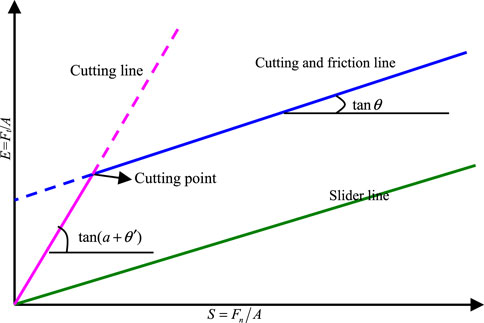
FIGURE 2. Synthetic model for drilling (modified from Dagrain, 2001). Note: the x-coordinate S is the special energy, and the y-coordinate E is the drilling intensity. S is obtained by dividing the torque force by the force-bearing area, and the ratio of the thrust to the force-bearing area is E.
For low thrust force (below the cutting point), the value of the friction force
By substituting Eqs 32, 33 into Eqs 38, 39, the axial force
The linear of Ft-A and Fn-A are dependent on the contact friction (θ) in the side of diamond particle, frictional angle (φ’) between the intact rock and compressed crushed zone, the rake angle (a) of the diamond particle, and internal friction angle of intact rock (φ). The value of Ft/Fn is a constant as follows (Kalantari et al., 2018; 2019)
For high thrust force (beyond the cutting point), the relationship between the normal force Fn and tangential force Ft is dependent of the contact friction (θ) in the side of diamond particle, frictional angle (φ’), internal friction angle of intact rock (φ), and the rake angle (a) of the diamond particle. The normal force of diamond particle from the impregnated diamond bit is transferred to rock due to the created cross-sectional area. Hence, using Eq. 42, the friction appears in drilling with the impregnated diamond bit. In the diamond particle, the friction between the diamond particle end and side wearing face and rock, acting as a resistant force, plays an important part in the cutting process.
According to Eqs 41, 42, for high thrust force (beyond the cutting point) the contact friction (θ) in the side of diamond particle, frictional angle (φ’), and the rake angle of the diamond particle (a) are dominant factors. For the diamond core bit, the shape of each diamond particle impregnated in the bit is irregular, resulting in the difficulty and limitation of the measurement of the rake angle of each diamond particle. For a diamond core bit (see Figure 1A), due to the irregular shape of diamond grains in bit, we cannot accurately measure the rake angle (a) of the diamond particle, and assume that it is an unknown parameter. We can use the following five steps to predict the strength parameters of rock:
(1) According to Eq. 42, we can calculate the value of a + θ’ using the experimental results of the linear Ft - Fn relation for low thrust force (below the cutting point). According to Eq. 36, the value of the contact friction (θ) using the experimental results of the linear Ft—Fn relation for low thrust force. The contact friction angle θ’ of the diamond particle side wearing face and the contact friction angle θ are almost the same in cutting and friction process (Kalantari et al., 2018). Then, the rake angle (a) can be obtained according to Eqs 36, 42.
(2) The slope of linear Eqs 39, 41, 42 in low thrust force are an important factor. Using the obtained rake angle (a) and the contact friction (θ’) from the slope of Ft -Fn curve in high thrust force, after some algebraic manipulation from Eqs 24, 25, the value of φ’ can be calculated as
(3) Using the estimated friction angle (
(4) These slopes in Eq. 41 can obtained from the plotted drilling data (Fn -h) in low thrust force (below the cutting point) in the impregnated diamond bit. Using the parameters (θ, φ’, φ, and a) obtained from the steps (1)∼(3) and the slope of Fn -h, the cohesion C can be calculated according to Eq. 41. By utilizing the slope values from Eqs 36, 41, 42, along with Eqs 43, 44, we can accurately determine the values of five parameters (θ, φ′, φ, a, and C)
(5) Now using the obtained C and φ from the proposed method, the unconfined compressive strength of rock (Rc) is calculated as (Kalantari et al., 2018)
Where Rc is the unconfined compressive strength of intact rock.
A drilling process monitoring apparatus, known as the DPM (Drilling Monitoring Process) (see Figure 3), has been developed to predict the strength of the rock in the field (He et al., 2019). With an inner diameter of 60 mm, outer diameter of 70 mm, and drilling depth of 50 m, the DPM is capable of continuous measurement and recording of drilling operational data, including thrust force, torque, penetration rate, rotation speed, drilling depth, and penetration depth per rotation. As drilling depth increases, the DPM automatically saves the drilling operational data in an Excel file. The DPM has a maximum collection ability of 500 data points per second, enabling accurate storage of several hundred sets of drilling data. The digital drilling experimental equipment can provide the maximum power of 1050 W and the maximum rotation speed of 800 r/min. In this experiment, the control parameters are the rotation speed (w) and the penetration rate (v), while the thrust force and torque are obtained as the drilling response. An impregnated diamond bit is used as the drill bit in the DPM, which allows for drilling in the field with high accuracy and precision.
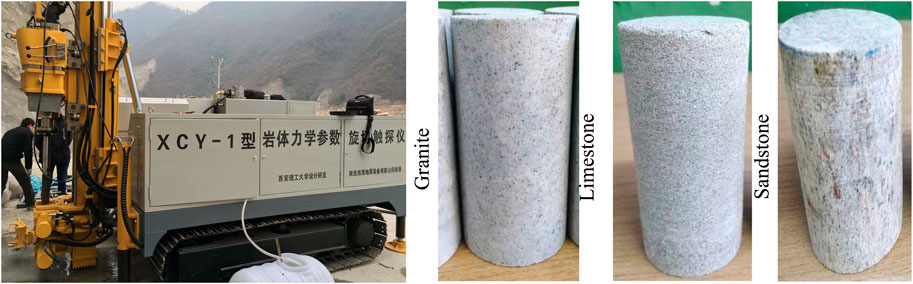
FIGURE 3. An overview of the drilling process monitoring apparatus (DPM) and part of drilled rock sample.
After conducting a study, it is essential for authors to discuss the results and their interpretation based on previous studies and working hypotheses. The discussion should include the implications of the findings in the broader context and explore their significance.
In this study, a drilling test using an impregnated diamond bit with an outer diameter of 70 mm and an inner diameter of 60 mm is performed, as depicted in Figure 1A. The drilling parameters, including the penetration rate and rotation speed, are varied for each rock type. The penetration rates for limestone, granite, marble, and sandstone are set in the range of 0.1–1.2 mm/min, and the rotation speeds are set in the range of 200–600 rpm for each rock type. The experiments are carried out on hard, medium, and weak rocks, such as granite, limestone, and sandstone. The cohesion and internal friction angle of each rock type are measured in the laboratory, following the ISRM standard.
Figure 4 displays the plots of the relationship between thrust force and penetration depth per rotation for sandstone, limestone, and granite under different confining pressures. Similarly, Figure 5 illustrates the relationship between torque force and penetration depth per rotation for each rock type under varying confining pressures. In the cutting process and the cutting and friction process, the thrust and torque forces linearly increase with the penetration depth per rotation. When low thrust and torque forces are applied on three rock types, the thrust and torque forces gradually increase with the depth of penetration per rotation. At a critical value defined as the cutting point by Lhomme (1999), the forces reach a maximum limit and cease to increase with further penetration depth per rotation. At shallow penetration depths, the friction force between the diamond particle and rock bottom sides is negligible and any increase in cutting force is due to the increase of penetration depth per rotation before it reaches the critical penetration depth (Detournay et al., 2008; Zhou and Detournay, 2014). Beyond the critical value of the penetration depth, the normal component of frictional force reaches a stable value and a limited value of the effective contact stress has also occurred (Rostamsowlat, 2018). In this stage, the incremental cutting response is governed by the pure cutting of the diamond particle. These findings from the impregnated diamond bit are consistent with those of other types of bits (Adachi, 1996; Dagrain, 2006; Detournay et al., 2008; Rostamsowlat et al., 2018).
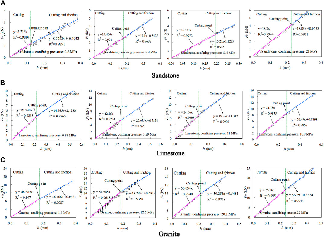
FIGURE 4. Plot of thrust force as a function of penetration depth per rotation at four different confining stresses. (A) Sandstone, (B) Limestone, and (C) Granite.
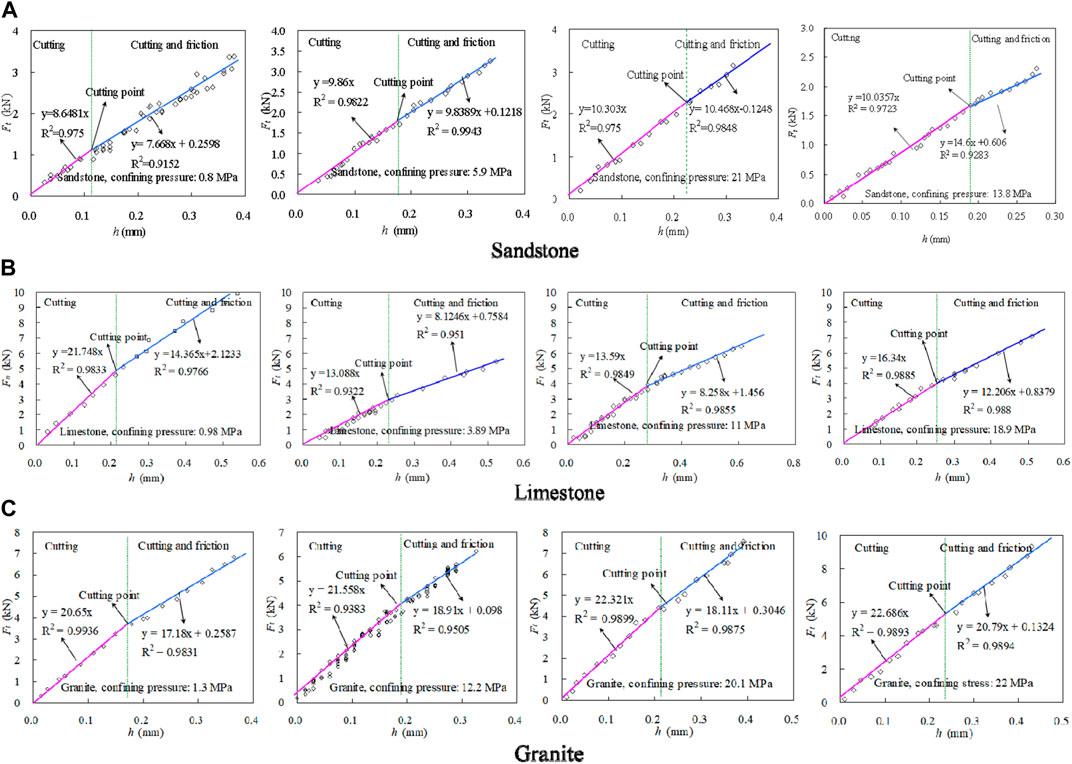
FIGURE 5. Plot of torque force as a function of penetration depth per rotation at four different confining stresses. (A) Sandstone, (B) Limestone, and (C) Granite.
In addition, the relationship between the thrust force, torque force, and critical penetration depth at the cutting point is affected by the confining pressure (Pf), as shown in Table 1. The confining pressure was varied between 0.8 MPa and 22 MPa, resulting in critical penetration depth ranges of 0.123–0.228 mm for sandstone, 0.233–0.255 mm for limestone, and 0.181–0.215 mm for granite. The cutting point for each rock type is influenced by the confining pressure during the drilling process, which can be seen in the slope variation of the Fn ∼h and Ft ∼h relationships in the cutting process and the cutting and friction process. The study’s findings indicate that the confining pressure (Pf) has a significant impact on the cutting response of the impregnated diamond bit in both cutting and cutting and friction regimes, as illustrated in Figures 4, 5. The confining pressure can affect the elastic and elastoplastic regimes of frictional contact, depending on the two regimes of frictional contact (Rostamsowlat et al., 2018).
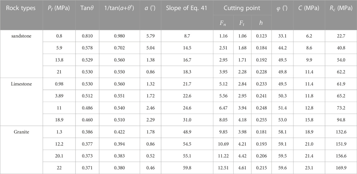
TABLE 1. Rocks parameters obtained from drilling tests.
Figure 6 depicts the torque force versus thrust force plots for sandstone, limestone, and granite. The cutting point, which depends on the predominance of the cutting process, varies with different confining pressures in the Ft/Fn relation of the impregnated diamond bit. The data points of the Ft/Fn relation follow a linear path with a low slope in the friction process, while points on another path follow the same path as the Ft/Fn linear relation if the drilling is dominated by the cutting process (Dagrain, 2001). For the impregnated diamond bit, the data obtained between these two paths of the Ft/Fn linear relation represent a combination of friction and cutting processes, as shown in Table 1. Most of the data points from the two paths were located in the cutting point under different confining pressures. It is evident that the role of the cutting process and friction process depends on the confining pressure. In other words, the slope of the Ft∼Fn linear relation varies with the confining pressure in the drilling process. As the confining pressure increases, the penetration depth increases with high thrust force and cutting force, which are provided simultaneously.
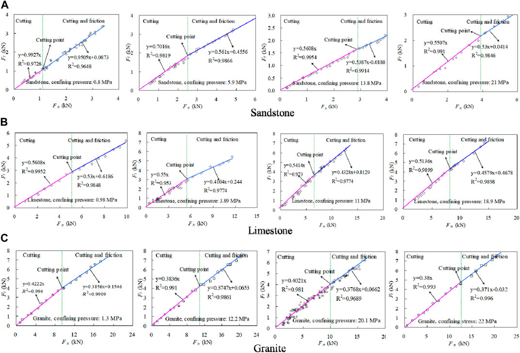
FIGURE 6. Plot of torque force as a function of thrust force at four different confining stresses. (A) Sandstone, (B) Limestone, and (C) Granite.
During the drilling process using an impregnated diamond bit, the diamond particles on the bit penetrate into the rock and create a penetration depth. As the bit rotates, it cuts through the rock, while the slope of the Ft∼Fn linear equation is determined by the contact friction and the intercept value is dependent on the penetration depth. This relationship is affected by various factors such as the crushed zone, rock properties, bit geometric parameters, and confining pressure, as demonstrated in Eq. 36. Through a least-squares regression, the correlation between the thrust force and torque force in the cutting and friction process can be plotted as a linear curve, as illustrated in Figure 6; Table 1. The correlation coefficients of the curves are almost always greater than 0.95. Consequently, the slopes of the trend lines can be determined, with one slope attributed to the cutting process and the other slope representing the cutting and friction process. Furthermore, the slopes of the trend lines from the cutting and friction process exhibit higher values at relatively low confining pressure. The obtained slopes of the Ft∼Fn linear curves for both cutting and cutting with friction processes, as shown in Figure 6, can be used to determine the rock parameters through the established model. This model yields the frictional angle, the dilation angle, and the internal friction angle of the rocks. Figures 4, 5 depict significant variations in torque and thrust forces concerning the depth of penetration during the cutting process. Through a least-squares regression of the torque and thrust forces versus the depth of penetration per rotation for both cutting and friction processes, a linear curve is obtained for the diamond core bit, as shown in Figures 4, 5, with correlation coefficients (R2) greater than 0.95, satisfying Eqs 36, 41. Moreover, the obtained slopes of the linear Fn ∼h curves during the drilling process can be used to calculate the cohesion of the rock, as presented in Table 1. The unconfined compressive strength of the rock (Rc) can then be obtained from Eq. 45, also shown in Table 1. The drilling tests under different confining pressures have yielded results for the strength of sandstone, limestone, and granite, which agree well with those from standard tests, with an error within 10%, as illustrated in Figure 7.
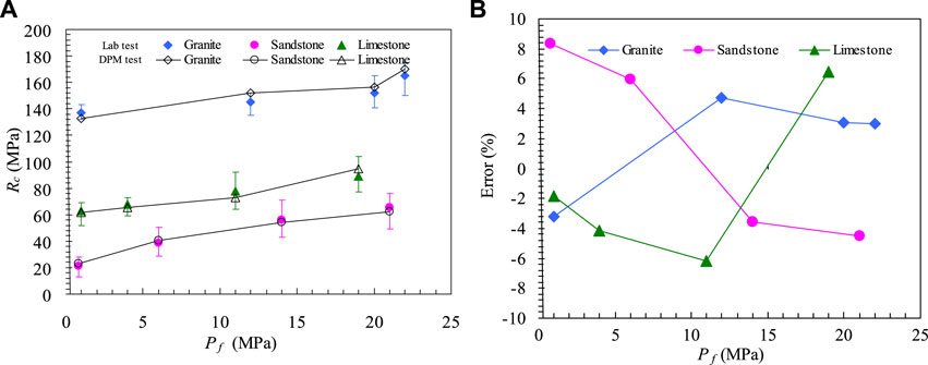
FIGURE 7. The obtained results for the strength of sandstone, limestone and granite from the drilling tests. (A) the strength result (B) the strength error.
The irregular shape of diamond particles in impregnated diamond bits makes it challenging to determine the rake angle of the particles. However, the slope of the Ft/Fn linear curves for cutting and friction processes can be used to calculate the rake angle a for the three types of rock using Eqs 36, 42. Table 1 shows the slopes of trend lines for cutting and friction processes in sandstone, limestone, and granite. The side wearing face of the diamond particles has nearly the same values of and during cutting and friction processes (Li et al., 2016). By replacing with in Eqs 36, 42, the rake angle a can be estimated, which is considered negligible for the estimated results (Bingham, 1964; Roxborough and Philips, 1975; Hibb and Flom, 1978; Karasawa and Misawa, 1992; Li et al., 1993; Richard et al., 1998; Sinor et al., 1998). Using Eqs 36, 41–45, the rock strength can be estimated. The parameters and confining pressure are related to the rock strength. The effect of parameter on the estimated cohesion is negligible at low confining pressure when the range of is 30°∼70°, which is close to the internal friction angles of all natural rocks, as shown in Figure 8. However, for high confining pressure (Pf>30 MPa) and low range, the effect of parameter on the estimated cohesion must be considered. The proposed method can practically estimate the strength parameters of rock, although there might be slight overestimation or underestimation of the strength for the three rock types, making the method reliable for estimating strength parameters.
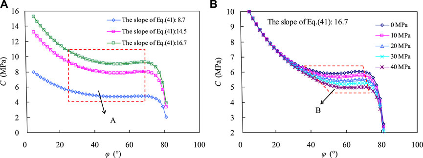
FIGURE 8. Variations of the estimated cohesion from the internal friction angle. (A) Different confining pressures (B) different fluid column pressures.
This study conducted a drilling process monitoring experiment to investigate the effect of confining pressure on cutting response with an impregnated diamond bit on sandstone, limestone, and granite.
(1) The relationship between thrust force, torque force, and penetration depth was analyzed for both cutting and friction regimes under varying confining pressures.
(2) An analytical model, which accounted for gravity effects, compressed crushed zones, and bit geometry, was developed. Results for high, medium, and weak strength rock suggest that drilling with an impregnated diamond bit involves two simultaneous processes of rock cutting and frictional contact, with the dominant role depending on the cutting point. Confining pressure was found to significantly affect the cutting response in both regimes, with increased thrust force, torque force, and penetration depth at the cutting point under higher confining pressure.
(3) Furthermore, a new field measurement method was proposed to determine cohesion, internal friction angle, and unconfined compressive strength of sandstone, limestone, and granite. The estimated strength values for the three rock types using this drilling technique are in good agreement with those of standard laboratory tests. The results demonstrate that the estimated strength of rocks is within an accepted error range of 10% compared to the results from standard tests. The drilling method provides a number of advantages over conventional tests, including high-resolution and continuous field measurement of rock strength parameters. With minimum requirements for test preparation, this practical method shows great potential for field applications in rock engineering.
The original contributions presented in the study are included in the article/supplementary material, further inquiries can be directed to the corresponding author.
YoZ, JZ, and MH contributed to conception and design of the study. ZX organized the database. YG and YiZ performed the statistical analysis. SC and HX wrote the first draft of the manuscript. DC, MH, and CF wrote sections of the manuscript. All authors contributed to manuscript revision, read, and approved the submitted version.
This research is financially supported by the Key R&D and Transformation Plan of Qinghai Province (2021-SF-167).
YZ, JZ, ZX, YG, SC, DC, and CF was employed by the company Geological Research Institute, China National Logging Corporation; HX was employed by the company Qinghai Xihu Expressway Management Co., Ltd.
The remaining authors declare that the research was conducted in the absence of any commercial or financial relationships that could be construed as a potential conflict of interest.
All claims expressed in this article are solely those of the authors and do not necessarily represent those of their affiliated organizations, or those of the publisher, the editors and the reviewers. Any product that may be evaluated in this article, or claim that may be made by its manufacturer, is not guaranteed or endorsed by the publisher.
a, rake angle of drill bit; A, cutting area of the drilling bit; C, cohesion of intact rock; Ft, tangential force; Fn, thrust force; Fcn, normal components of the cutting force; Fct, tangential components of the cutting force; Fnw, normal components of the friction force; Ftw, tangential components of the friction force in the front end of diamond particle; Fh, normal force in the back end of diamond particle; Fh, sina frictional force between the diamond particle and rock sides; k, number of drill bits; Pf, confining pressure; Pm, fluid column pressure in the drilling hole; v, drilling speed; w, rotation speed; τ0, shear stress of the crushed zone; σ0, principal stress of the crushed zone; φ′, friction angle of the crushed zone; σ2, normal stress in the fracture surface; τ2, shear stress in the fracture surface; φ, internal friction angle of intact rock; θ, rock-bit contact angle; ψ, propagating angle of the crushed zone; τ, total shear stress of rock fragment; σ, total normal stress of rock fragment; β, angle of shear plane in the back of the blade; σ1, normal stress caused by the ground stress; τ2, shear stress caused by the ground stress.
Adachi, J. I. (1996). Frictional contact in rock cutting with blunt tools. Civil Engineering, University of Minnesota. M. Sc Thesis.
Burgess, T. M., and Less, W. G. (1985). “Measuring the wear of milled tooth bits using MWD torque and weight-on-bit,” in Proceedings of the drilling conference SPE/IADC (New Orleans, 453–462.
Chiaia, B., Borri-Brunetto, M., and Carpinteri, A. (2013). Mechanical modelling of the mechanics of core drilling in geomaterials. Mach. Sci. Technol. 17, 1–25. doi:10.1080/10910344.2012.747881
Chong, Z. R., Yang, S. H. B., Babu, P., Linga, P., and Li, X. S. (2016). Review of natural gas hydrates as an energy resource: Prospects and challenges. Appl. Energy 162, 1633–1652. doi:10.1016/j.apenergy.2014.12.061
Dagrain, F. (2006). Etude des mecanismes de coupe des roches avec couteaux Uses Approche des mécanismes de frottement sous les couteaux par le concept du troisième corps. Faculté Polytechnique de Mons. Ph.D Thesis.
Dagrain, F. (2001). Influence of the cutter geometry in rock cutting: An experimental approach. University of Minnesota. M. Sc Thesis.
Detournay, E., and Defourny, P. (1992). A phenomenological model for the drilling action of drag bits. Int. J. Rock Mech. Min. Sci. 29, 13–23. doi:10.1016/0148-9062(92)91041-3
Detournay, E., Richard, T., and Shepherd, M. (2008). Drilling response of drag bits: Theory and experiment. Int. J. Rock Mech. Min. Sci. 45, 1347–1360. doi:10.1016/j.ijrmms.2008.01.010
Evans, I. (1962). “A theory on the basic mechanics of coal ploughing,” in Proceedings of international symposium on mining research (London 2, 761–798.
Franca, L. F. P. (2010). Drilling action of roller-cone bits: Modeling and experimental validation. J. Energy Resour. Technol. 132, 1–9. doi:10.1115/1.4003168
Gerbaud, L., Menand, S., and Sellami, H. (2006). “PDC Bits: All comes from the cutter rock interaction,” in Proceedings of the IADC/SPE drilling conference held in miami, 2 (Florida, USA, 21–23.
Hareland, G. A. (2010). “Drilling rate model for roller cone bits and its application,” in Proceedings of the CPS/SPE international oil & gas conference and exhibition in China held in beijing, China, 8–10.
He, M. M., Li, N., Zhang, Z. Q., Yao, X. C., Chen, Y. S., and Zhu, C. H. (2019). An empirical method for determining the mechanical properties of jointed rock mass using drilling energy. Int. J. Rock Mech. Min. Sci. 116, 64–74. doi:10.1016/j.ijrmms.2019.03.010
Hibb, L. E. J., and Flom, D. G. (1978). Diamond compact cutter studies for geothermal bit design. J. Press. Vessel Tech. 100 (4), 406–416. doi:10.1115/1.3454488
Hoberock, L., and Bratcher, G. J. (1996). A new approach for determining in-situ rock strength while drilling. J. Energy Resour. Technol. 118, 249–255. doi:10.1115/1.2793870
Hoover, E. R., and Middleton, J. N. (1981). Laboratory evaluation of PDC drill bits under high-speed and high-wear conditions. J. Petro Tech. 33 (12), 2316–2321. doi:10.2118/10326-pa
Kalantari, S., Baghbanan, A., and Hashemolhosseini, H. (2019). An analytical model for estimating rock strength parameters from small-scale drilling data. J. Rock Mech. Geotech. Eng. 104, 135–145. doi:10.1016/j.jrmge.2018.09.005
Kalantari, S., Hashemolhosseini, H., and Baghbanan, A. (2018). Estimating rock strength parameters using drilling data. Int. J. Rock Mech. Min. Sci. 104, 45–52. doi:10.1016/j.ijrmms.2018.02.013
Karasawa, H., and Misawa, S. (1992). Laboratory testing to design PDC bits for geothermal well drilling. Drilling Technology. Am. Soc. Mech. Eng. (ASME) 40, 135–141.
Karasawa, H., Ohno, T., Kosugi, M., and Rowley, J. C. (2002b). Methods to estimate the rock strength and tooth wear while drilling with roller-bits-part 1: Milled-Tooth Bits. J. Energy Resour. Technol. 24, 125–132. doi:10.1115/1.1482405
Karasawa, H., Ohno, T., Kosugi, M., and Rowley, J. C. (2002a). Methods to estimate the rock strength and tooth wear while drilling with roller-bits-part 2: Insert bits. J. Energy Resour. Technol. 124, 133–140. doi:10.1115/1.1482406
Kerisel, J. (1975). Cours de mécanique des sols. Paris: Ecole National Des Ponts Et Chaussées. (in French).
Lhomme, T. (1999). Frictional contact at a rock-tool interface: An experimental study. University of Minnesota. M. Sc Thesis.
Li, X., Hood, M., and Find, X. X. (1993). Wear and damage to PDC bits, 3. Society of Petroleum Engineers Journal, 267–294.
Li, X. S., Xu, C. G., Zhang, Y., Ruan, X. K., Li, G., and Wang, Y. (2016). Investigation into gas production from natural gas hydrate: A review. Appl. Energy 172, 286–322. doi:10.1016/j.apenergy.2016.03.101
Lia, Z., and Itakura, K. (2012). An analytical drilling model of drag bits for evaluation of rock strength. Soils Found. 52 (2), 216–227. doi:10.1016/j.sandf.2012.02.002
Merchant, M. E. (1945). Basic mechanics of the metal cutting process. J. Appl. Phys. 66, 168–175. doi:10.1115/1.4009380
Naeimipour, A., Rostami, J., Buyuksagis, I. S., and Frough, O. (2018). Estimation of rock strength using scratch test by a miniature disc cutter on rock cores or inside boreholes. Int. J. Rock Mech. Min. Sci. 107, 9–18. doi:10.1016/j.ijrmms.2018.03.020
Nakajima, I., and Kinoshita, S. (1979). Theoretical studies on cutting force of rock fracture mechanism in rock cutting. J. Min. Metall. Inst. Jpn. 95, 49–55. doi:10.2473/shigentosozai1953.95.1092_49
Nishimatsu, Y. (1972). The mechanics of rock cutting. Int. J. Rock Mech. Min. Sci. 9, 261–270. doi:10.1016/0148-9062(72)90027-7
Ohno, T., Karasawa, H., Kosugi, M., and Rowley, J. C. (2004). Proposed practical methods to estimate rock strength and tooth wear while drilling with roller-cone bits. J. Energy Resour. Technol. 126, 302–310. doi:10.1115/1.1794696
Palassi, M., and Emami, V. (2014). A new nail penetration test for estimation of rock strength. Int. J. Rock Mech. Min. Sci. 66, 124–127. doi:10.1016/j.ijrmms.2013.12.016
Pessier, R. C., and Fear, M. J. (1992). “Quantifying common drilling problems with mechanical specific energy and a bit-specific coefficient of sliding friction,” in Proceedings of the 67th annual technical conference and exposition of the SPE, 4-7 (Washington, DC, 373–387.
Richard, T., Dagrain, F., Poyol, E., and Detournay, E. (2012). Rock strength determination from scratch tests. Eng. Geol. 147-148, 91–100. doi:10.1016/j.enggeo.2012.07.011
Richard, T., Detoumay, E., Drescher, A., Nicodeme, P., and Fourmaintraux, D. (1998). “The scratch test as a means to measure strength of sedimentary rocks,” in Proceedings of the SPE/ISRM rock mechanics in petroleum engineering (Society of Petroleum Engineers), 15–22.
Rostamsowlat, I., Akbari, B., and Evans, B. (2018). Analysis of rock cutting process with a blunt PDC cutter under different wear flat inclination angles. J. Petro Sci. Eng. 171, 771–783. doi:10.1016/j.petrol.2018.06.003
Rostamsowlat, I. (2018). Effect of cutting tool properties and depth of cut in rock cutting: An experimental study. Rock Mech. Rock Eng. 51 (6), 1715–1728. doi:10.1007/s00603-018-1440-2
Roxborough, F. F., and Philips, H. R. (1975). Rock excavation by disc cutter. Int. J. Rock Mech. Min. Sci. 12 (12), 361–366. doi:10.1016/0148-9062(75)90547-1
Sinor, L. A., Powers, J. R., and Warren, T. M. (1998). “The effect of PDC cutter density, back rake size and speed on performance,” in Proceedings of the IADC/SPE drilling conference (Society of Petroleum Engineers). No. SPE-39306-MS.
Teale, R. (1965). The concept of specific energy in rock drilling. Int. J. Rock Mech. Min. Sci. 2, 245–273. doi:10.1016/0148-9062(65)90016-1
Vedachalam, N., Ramesh, S., Srinivasalu, S., Rajendran, G., Ramadass, G., and Atmanand, M. (2016). Assessment of methane gas production from Indian gas hydrate petroleum systems. Appl. Energy 168, 649–660. doi:10.1016/j.apenergy.2016.01.117
Warren, T. M. (1987). Penetration rate performance of roller cone bits. SPE Drill. Eng. 2, 9–18. doi:10.2118/13259-pa
Wojtanowicz, A. K., and Kuru, E. (1993). Mathematical modeling of PDC bit drilling process based on a single-cutter mechanics. J. Energy Resour. Technol. 115, 247–256. doi:10.1115/1.2906429
Wolcott, D. S., and Bordelon, D. R. (1993). “Lithology determination using downhole bit mechanics data,” in Proceedings of the 68th annual technical conference and exhibition of the SPE, 3-6 (Houston, Texas, 769–778.
Yang, M., Luo, D. Y., Chen, Y. H., Li, G., Tang, D. Q., and Meng, Y. F. (2019). Establishing a practical method to accurately determine and manage wellbore thermal behavior in high-temperature drilling. Appl. Energy 238, 1471–1483. doi:10.1016/j.apenergy.2019.01.164
Keywords: advanced prediction, analytical model, rock strength parameters, drilling process monitoring, confining pressure
Citation: Zhang Y, Zhao J, Xiao Z, Gao Y, Cui S, Cheng D, He M, Fang C, Xue H and Zhao Y (2023) Estimation of mechanics parameters of rock in consideration of confining pressure using monitoring while drilling data. Front. Earth Sci. 11:1169712. doi: 10.3389/feart.2023.1169712
Received: 20 February 2023; Accepted: 17 March 2023;
Published: 13 April 2023.
Edited by:
Xuelong Li, Shandong University of Science and Technology, ChinaReviewed by:
Zihan Liu, The University of Hong Kong, Hong Kong SAR, ChinaCopyright © 2023 Zhang, Zhao, Xiao, Gao, Cui, Cheng, He, Fang, Xue and Zhao. This is an open-access article distributed under the terms of the Creative Commons Attribution License (CC BY). The use, distribution or reproduction in other forums is permitted, provided the original author(s) and the copyright owner(s) are credited and that the original publication in this journal is cited, in accordance with accepted academic practice. No use, distribution or reproduction is permitted which does not comply with these terms.
*Correspondence: Mingming He, aGVtaW5nbWluZ0B4YXV0LmVkdS5jbg==
Disclaimer: All claims expressed in this article are solely those of the authors and do not necessarily represent those of their affiliated organizations, or those of the publisher, the editors and the reviewers. Any product that may be evaluated in this article or claim that may be made by its manufacturer is not guaranteed or endorsed by the publisher.
Research integrity at Frontiers
Learn more about the work of our research integrity team to safeguard the quality of each article we publish.