 Mu Li1,2
 Hengrui Zhang
94% of researchers rate our articles as excellent or good
Learn more about the work of our research integrity team to safeguard the quality of each article we publish.
Find out more
ORIGINAL RESEARCH article
Front. Earth Sci. , 22 March 2023
Sec. Economic Geology
Volume 11 - 2023 | https://doi.org/10.3389/feart.2023.1164839
This article is part of the Research Topic Mechanics and Seepage Behaviors of Deep Reservoir Rocks View all 7 articles
Since pressure while drilling (PWD) has the disadvantages of single-point measurement and high cost of application, a micro-measurer based on MEMS (micro-electromechanical systems) sensor technology, which can measure downhole temperature, pressure, magnetic field, and dynamic signal, has been developed to achieve real-time, efficient, and accurate measurement of multiple parameters in the well. The kernel circuit system is the core of measurement and control, and the shell plays the role in protecting the kernel circuit. The shell of the micro-measurer is made of preferably selected materials with high-temperature and high-pressure resistance, corrosion resistance, small size, and low density, which can adapt to working in drilling fluid for a long time. The micro-measurer uses integrated interfaces on the shell to enable communication between the host computer and measuring machine. Based on the field test, both the functional integrity and data measurement accuracy of the micro-measurer are verified. Through analysis of the measured data, the profile of the downhole temperature field is constructed. The physical phenomena reflected by the measured magnetic field signal and dynamic signal are consistent with the actual working conditions observed in the test. Hence, as a new microchip measuring device, the micro-measurer can better serve the drilling engineering field and provide technical support for real-time measurement of downhole parameters in the future.
As drilling operations are gradually carried out in deeper formations, the importance of unconventional oil and gas resource extraction is gradually increasing. The downhole pressure in the drilling process is susceptible to factors such as fracture propagation, which makes the wellbore parameters variable and difficult to monitor, and the real-time measurement of downhole parameters is an important means to ensure wellbore safety (Tan et al., 2020; Li et al., 2021; Yin et al., 2022). Therefore, it is necessary to develop a real-time measurement tool for downhole engineering parameters. PWD is an effective way to obtain wellbore engineering parameters in real time. Many oil companies and researchers have carried out in-depth research on downhole temperature and pressure measurement technology and supporting tools, gradually forming the main modes, such as single-point measurement, double-point measurement, and intelligent drill pipe multi-point measurement.
For the downhole single-point measurement mode, Schlumberger, Baker Hughes, Halliburton, and other companies have developed PWD tools with better performance after decades of development (Cantarelli et al., 2017; Sobie et al., 2018; Taler et al., 2018; Baumgartner et al., 2019). Guan et al. (2011), Geng et al. (2020), and Zhang et al. (2016) have attacked the measurement parameters, data storage, and transmission, respectively. The limited range and single dimension of downhole single-point measurement cannot realize the real-time measurement of temperature and pressure profiles in the wellbore, which makes it difficult to meet the demand of safe drilling under the conditions of a complex formation pressure system in a long bare section of deep wells. Li et al. (2017a) and Liu et al. (2009) were the first to propose a dual-point multi-parameter measurement method and developed a downhole dual-point PWD tool to achieve dual-point accurate measurement of 10 parameters including near-bit temperature, pressure, and XYZ triaxial vibration. An intelligent drill pipe has been used commercially since 2006, and drilling safety and efficiency can be improved by downhole multi-point measurement. Li et al. (2022) established an intelligent prediction system for downhole overflow and leakage by fusing multiple downhole parameters using a neural network intelligence algorithm. Although downhole dual-point and multi-point measurement methods significantly improve the characterization dimension of wellbore temperature and pressure measurements, they are currently of limited extension and expensive to use, with poor applicability in drilling.
In recent years, MEMS (micro-electromechanical systems) technology has been developing rapidly. MEMS is a method that combines electrical and mechanical components to build tiny integrated devices or systems. The size ranges from a few micrometers to millimeters. MEMS sensors are manufactured using the integrated circuit (IC) batch processing techniques (Rochus et al., 2016). Due to the characteristics of light mass, small size, low energy consumption, high accuracy, good stability, high integration, and resistance to harsh working conditions, MEMS microchip sensors are gradually applied to the development of various types of measuring tools. In the field of oil and gas engineering, the measurement technology based on MEMS sensors has been widely recognized in recent years. In 2018, MEMS sensor technology was selected as one of the top ten international oil technology advances. In 2021, at the International Offshore Oil and Gas Technology Conference (OTC), INGU Pipers’ miniature measuring tool with MEMS sensors for temperature, pressure, and inertia won the “Spotlight on New Technology” award. As the global deep oil and gas exploration and development continue to advance, the requirements for measurement under complex wellbore conditions are increasing, and the disadvantages of traditional sensors, which include being large, easily damaged, and costly, are becoming increasingly prominent, while the micro-measurement technology based on MEMS has a broad development space (Fu, 2019).
Recently, several oil companies and institutions (Li et al., 2017b) (Shi et al., 2020) have developed microsphere chip measurement tools, which mainly consist of chemical protective coatings, temperature and pressure sensors, and surface devices. An indoor experimental test and field test have been carried out. The feasibility of using micro-measurement tools for downhole temperature and pressure measurement has been demonstrated.
In comparison with the current stage of micro-measurer measurement technology in various countries, it can be found that the measurement gaps of microchips developed in various countries are reflected in the measurement pressure and working temperature. The micro-measurer tools of all countries have problems such as low recovery rate and serious breakage in field tests. Therefore, it is still necessary to continue relevant research for improving the strength, recovery rate, and integrity of micro-measurement tools to break the limitations of recovery rate, breakage, depth positioning, and error compensation. Efforts should be made to improve the tolerance of microchips to high-level temperature and pressure and the measurement capability of high precision temperature and pressure in an extreme environment, so that they can not only be resistant to high temperature and pressure but also be able to sense small changes to accurately measure temperature and pressure.
In summary, compared with downhole measuring equipment using traditional sensors, the downhole micro-measurer has certain advantages in terms of application flexibility, scalability, environmental tolerance, and low cost and can also achieve effective characterization of wellbore temperature and pressure profiles, which requires in depth study.
This study describes in detail the structure of the micro-measurer and the composition of the kernel system and briefly describes how the external shell of the micro-measurer is prepared. With the complete introduction of various information about the micro-measurer, the field test is used to verify the various test functions of the micro-measurer.
The micro-measurer is mainly composed of the kernel system and the outer shell. Specifically, the kernel system is the core of program control, parameter measurement, data processing, and storage, which mainly consists of rigid–flexible circuit boards, low-power microcontroller, temperature sensor, magnetometer, gyroscope accelerometer, Wheatstone bridge-based voltage measuring circuit, and other electronic components on the circuit board. The outer shell encapsulates its internal micro-kernel system from the drilling fluid, thus protecting the kernel system from fluid erosion and the influence of friction damage. Meanwhile, to wake up the micro-measurer from the low-power mode and transmit the collected data, the shell also integrates the activation interface and the low-power data transmission interface for communication with the host computer. The structure of the micro-measurer is shown in Figure 1.
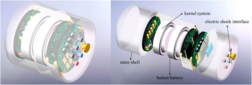
FIGURE 1. Structure of the micro-measurer.
Because the size of the micro-measurer is strictly limited by the bit water way, the kernel system must have a small geometry to ensure the measurer’s passability into the wellbore. The micro-measurer can only rely on battery power when collecting data in the wellbore. Due to size constraints, the power supply unit of the measuring device is a micro-button-battery with a diameter of 9.5 mm and a total battery capacity of 53 mA h. The power consumption of each measurement module in the kernel system needs to be strictly controlled, to enable the micro-measurer to achieve multi-parameter measurement in the well over 5 h under the constraints of the total battery capacity.
The kernel system possesses the characteristics of small size and also needs to realize the collaborative measurement of multiple parameters in the wellbore. For this purpose, a low-power, high-precision digital temperature sensor, a low-noise three-axis digital magnetic sensor, a high-precision six-axis gyroscope accelerometer sensor, and a Wheatstone bridge-based pressure measurement module are selected to achieve low-power measurement of four types of parameters in the wellbore: temperature, pressure, magnetic field, and dynamics.
In addition, in order to store all the measurement data, an ultra-low-power microcontroller of STM32L4 series with built-in large-capacity flash memory is used as the control and processing core of the entire micro-measurer, further reducing the system power consumption and battery power consumption and extending the usage time of the tool.
At the same time, the reserved ultra-low-power external activation interface in the kernel system is able to quickly wake up the micro-measurer from the low-power shutdown mode to the running mode. The reserved low-power data transmission interface can realize the low-power data transmission and control commands between the micro-measurer and the host computer.
In summary, with the ultra-low power consumption design of the kernel system, its operating current can be maintained at approximately 3 mA, and the micro-measurer can operate for 17.66 h in principle when a micro-power supply unit with a capacity of 53 mA h is selected. Although the energy consumption of the micro-measurer generally increases slightly in high-temperature environments, it is fully capable of meeting the basic operating requirements of 5–10 h. The hardware schematic of the kernel system is shown in Figure 2.
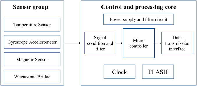
FIGURE 2. Hardware schematic of the kernel circuit system.
Due to the need for multi-parameter collaborative measurement of the wellbore flow field, the core system of the measuring device is equipped with multiple measurement modules. Each module contains a MEMS sensor chip and several electronic components in the auxiliary circuit. In addition, the kernel system is limited by strict size, which makes the design and device arrangement of the entire integrated circuit board extremely complex.
For this reason, this study adopts the design idea of combining rigid–flexible circuit boards into separate boards. Specifically, the entire circuit board consists of three circular rigid circuit boards of 10 mm diameter and two flexible circuit boards. In other words, a “three rigid + two flexible”-layered structure is used to minimize the size. The top and bottom layers of the rigid circuit board are arranged with different functional measurement modules. The flexible circuit boards are connected with the rigid circuit boards, which together constitute a complete circuit for the synergistic measurement of multi-physical fields (temperature, pressure, magnetism, and dynamics). The flexible circuit board has good bending characteristics, so the whole kernel system has a small volume by bending the flexible circuit board to ensure that it can be packaged in the external shell of the micro-measurer whose geometric size is strictly limited. The bent form of the kernel board of the measuring device is shown in Figure 3. The three circuit boards ①, ②, and ③ in the figure are four-layered rigid boards. The flexible boards ④ and ⑤ have only circuit alignments on them without arranging components and serve to stabilize the connection of the three four-layered rigid boards.
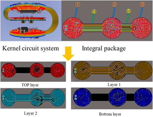
FIGURE 3. Kernel circuit system and its components.
As a result of the micro-measurer working in drilling fluid for a long time, it must possess the characteristics of high-temperature and high-pressure resistance, corrosion resistance, small size, and low density. Therefore, the high-strength polyether ether ketone (PEEK) material with controllable density classification is selected for shell preparation.
The material has a melting point of 343°C, a softening point of 168°C, and a tensile strength of 132–148 MPa. The outstanding characteristics of high-temperature and high-pressure resistance, corrosion resistance, and good mechanical properties can better adapt to the complex environment downhole. The mechanical properties can be further improved by means of carbon fiber composite.
To further improve the tightness of the kernel system and the pressure resistance of the measuring device, liquid polydimethylsiloxane (PDMS) silica gel-like material is used to fill the gap between the kernel system and the external shell, while the shell is cast to form a protective film, so that the micro-measurer forms an organic whole and improves its integral tightness.
The schematic diagram of the casting process and the packaged micro-measurer after encapsulation is shown in Figure 4. The maximum external dimension is strictly controlled to be 15 mm.
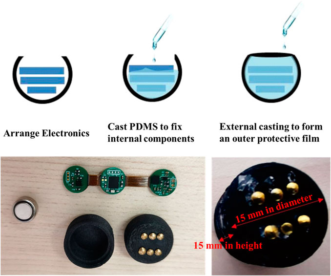
FIGURE 4. Packaged micro-measurer.
In order to verify the various measurement functions of the micro-measurer during actual downhole operation, downhole measurement tests are conducted at the drilling site.
The test equipment is shown in Figure 5. The depth from the wellhead to the bridge plug location is 200 m, the outer diameter of the drill pipe is 127 mm, and the inner diameter of the casing is approximately 230 mm. Since the depth of the wellbore used for the field test is only 200 m and the pressure in the wellbore does not vary significantly, the pressure measurement module of the micro-measurer is not turned on before the test. In other words, the micro-measurer measures only the temperature and magnetic field in the wellbore as well as the acceleration and angular rate of the micro-measurer itself in real time.
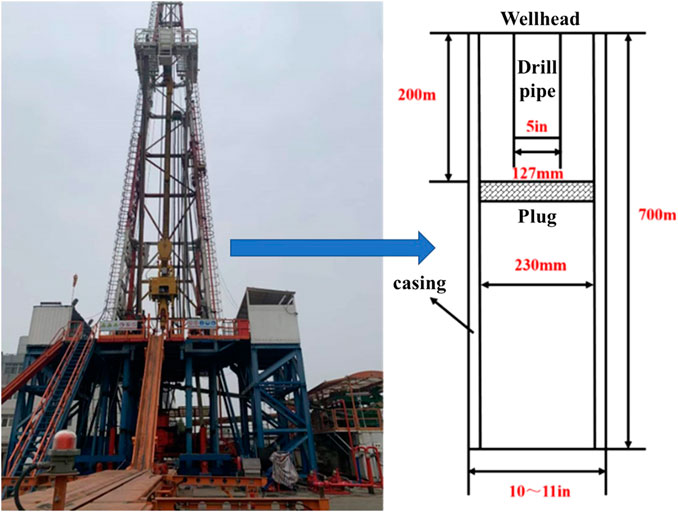
FIGURE 5. Field test drilling platform.
In the test, the micro-measurer is placed all-in-one measuring joint and mounted at the bottom end of the drill pipe. Lowering and lifting of the drill pipe allows the micro-measurer to travel the entire wellbore. Seven micro-measurers are placed in the measuring joint. The process of the whole test is shown in Figure 6.
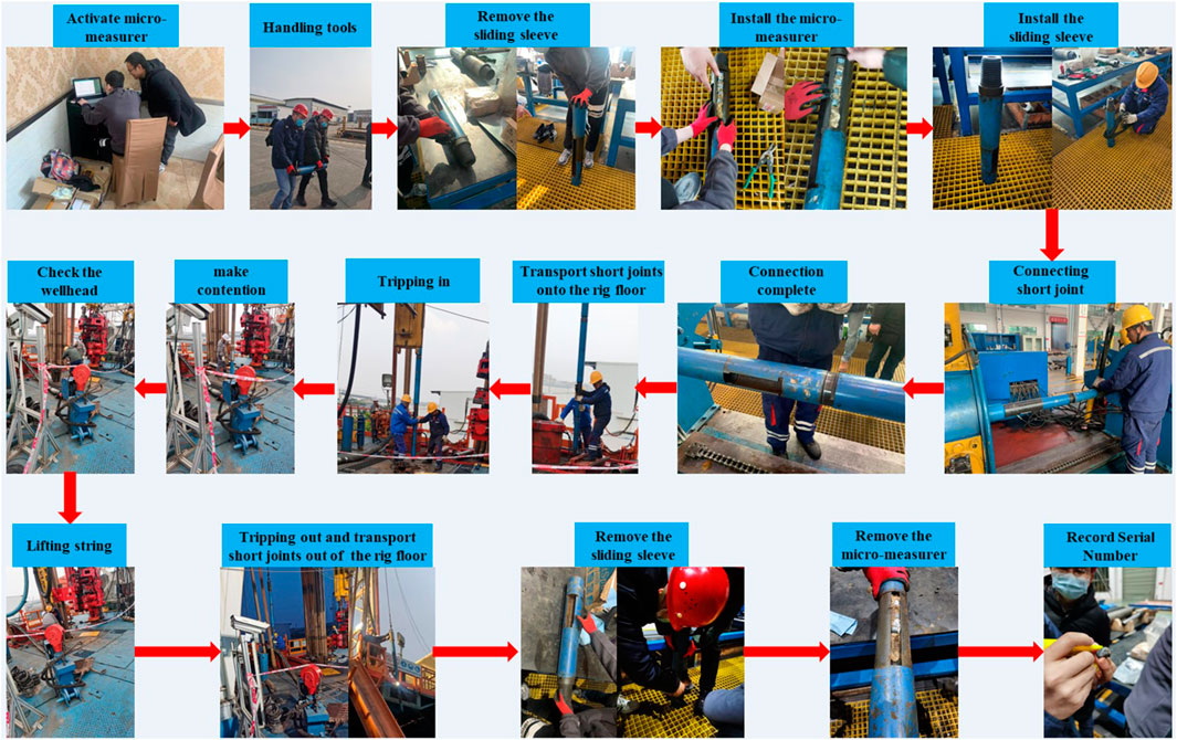
FIGURE 6. Field test process.
The length of the drill pipe used in the test is approximately 10 m. A stand column is connected to three drill pipes, and its length is approximately 30 m. A total of six complete stand columns are lowered during the whole test, and the seventh stand column is lowered halfway. The first five stand columns are lowered while rotating, while the sixth and seventh stand columns are lowered directly without rotating, and there is a long resting time after the single stand column is lowered. After the stand columns are lowered, they are all lifted out of the well, and all of them are lifted directly without rotation during the lifting process.
Finally, the temperature and triaxial magnetic field data measured by the micro-measurer that underwent a whole lowering and upper return process in the wellbore are shown in Figure 7. According to the measured temperature data, the micro-measurer is carried into the liquid environment in the wellbore from the outdoor condition where the temperature is low, and the temperature measured by the micro-measurer gradually increases, as the stand column is lowered, and gradually decreases during the stand column lifting, which proved that the measuring device can quickly and accurately detect the change in environmental temperature.
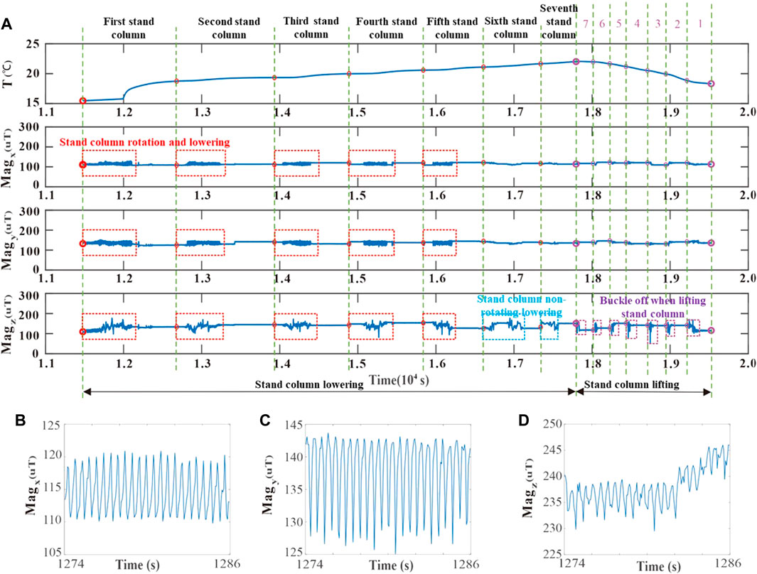
FIGURE 7. Time series of temperature and three-axis magnetic intensities. (A) Time series of temperature and three-axis magnetic intensities. (B) Data variation of magnetic field strength in X-axis with time. (C) Data variation of magnetic field strength in Y-axis with time. (D) Data variation of magnetic field strength in Z-axis with time.
For the measurement of the downhole magnetic field, the geomagnetic field is mainly measured using the magnetic sensor because there is no strong magnet in the whole wellbore environment. According to the distribution of the geomagnetic field, it is known that the magnitude and direction of the geomagnetic vector will change as the depth of the ground changes; thus, the axis of the magnetic sensor vertical to the ground will continuously change during the lowering and lifting of the stand column, while the axis parallel to the ground will only fluctuate periodically due to the change of its angle with the geomagnetic vector when the magnetic sensor is rotated.
Comparing the actually measured three-axis magnetic field data, the X- and Y-axes, which are parallel to the ground, show small periodic fluctuations in their magnetic fields when the stand column is rotated and lowered, as shown in detail in Figures 7B, C. However, there are no magnetic field fluctuations when the stand column is non-rotated, lowered, and lifted. The magnetic field of the Z-axis is vertical to the ground, which shows significant and continuous fluctuations in both rotating lowering stand column and non-rotating lowering and lifting stand column, as shown in Figure 7D.
The measured magnetic field data are used to calibrate the position of the micro-measurer in the pipe string, and the temperature data measured using the device during the test are converted between time and depth. Then, the variation in temperature with depth is obtained, as shown in Figure 8, providing a feasible solution for the construction of the downhole temperature profile.
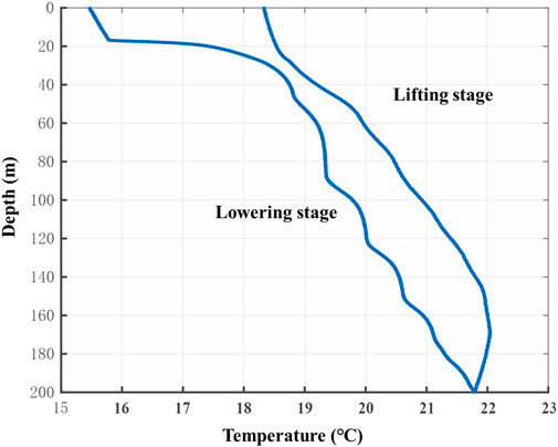
FIGURE 8. Temperature–depth curve.
The triaxial acceleration and angular rate around the triaxial axis measured using the micro-measurer during lowering and lifting of stand columns in the wellbore are shown in Figure 9. From the measured data, the acceleration values measured using the accelerometer of the micro-measurer in the X and Y directions fluctuate significantly during lowering of the column with rotation. However, since the Z-axis of the accelerometer is parallel to the column axis and the column is lowered at a uniform speed, the acceleration of the Z-axis is basically maintained at a near-zero value. During the lifting of the stand column, the column is subjected to vibration for a short period when it is unbuckled, so the acceleration of all three axes changes abruptly around its stable value and then quickly returns to stability.
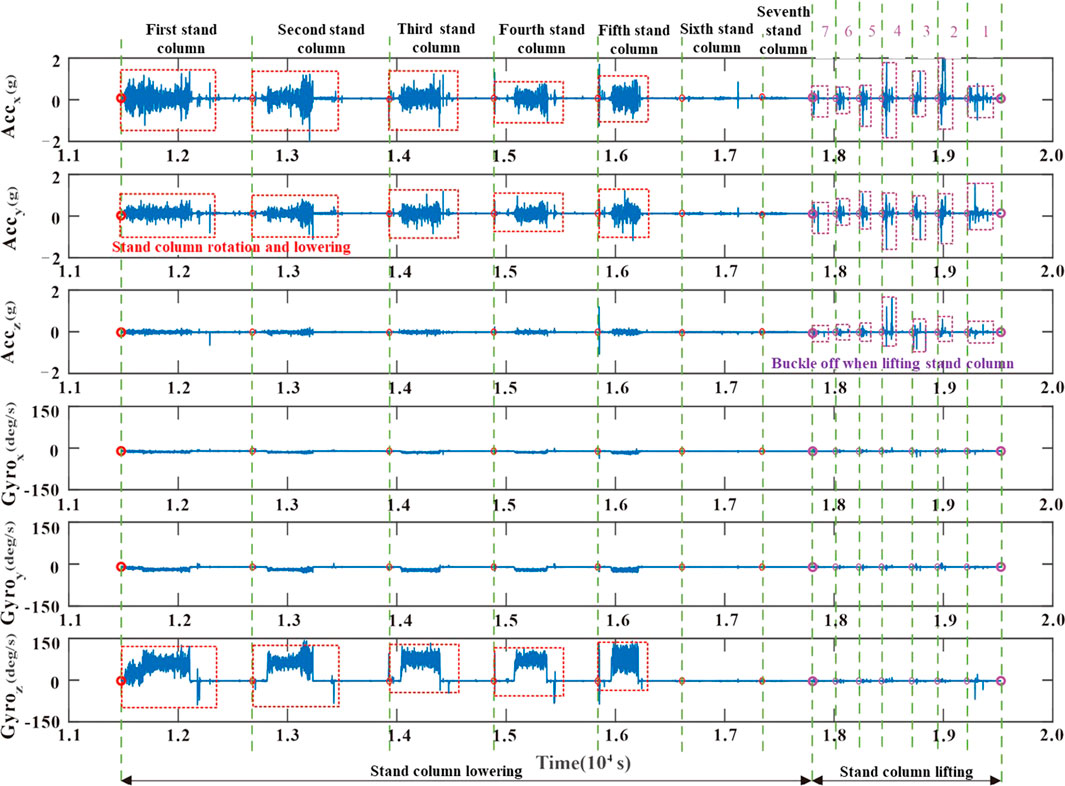
FIGURE 9. Time series of three-axis accelerations and angular rates.
In addition, since the short connection deposited in the micro-measurer rotates together with the drill string, the angular rate signal measured using the gyroscope in the micro-measurer can reflect the rotation of the drill string. The measured angular rate values of X- and Y-axes are stable around zero, indicating that the micro-measurer does not rotate around X- and Y-axes. Since the Z-axis is the rotation axis of the micro-measurer, the angular rate around the Z-axis shows obvious changes. In the process of non-rotating column lowering and column lifting, the three-axis angular rate value is constant at zero. In summary, the physical information reflected by the dynamic signal of the micro-measurer is consistent with the actual working conditions in the test.
In order to meet the requirements of the development of wellbore parameter measurement tools toward parameter diversification, module integration, extreme environment tolerance, and fast information transmission, a miniature measurement tool developed based on MEMS technology was born. The tool can dynamically circulate with the wellbore and record measurements in real time, regardless of complex formation conditions, and achieve ultra-small size, extremely low cost, and higher accuracy measurement capability of key parameters throughout the wellbore, providing key technical support for downhole working condition identification and wellbore safety control. Based on the results of the article, the advantages of our micro-measurer technology over other similar technologies are discussed as follows:
(1) In comparison with the single circuit board design used in existing micro-measurer tools, the microkernel system designed in this technology uses a combination of soft and hard circuit boards. The kernel circuit board consists of three circular rigid circuit boards (10 mm in diameter) and two flexible circuit boards, on which the rigid circuit boards are arranged with MEMS sensors and their auxiliary electronic components with different functions, and the rigid circuit boards are connected to each other by flexible circuit boards. This innovative design not only enables the micro-measurer tool to realize the synergistic measurement of multiple physical fields (temperature, pressure, magnetism, and dynamic) but also makes use of the bendability of the flexible circuit board to effectively reduce the size of the microcircuit, which further enables the entire micro-measurer measurement tool to become more compact.
(2) In comparison with the existing micro-measurer tools, which cannot be easily and quickly tested for integrity before entering the well, the microkernel system designed in this article is equipped with a low-power Bluetooth module, which can quickly test the measurement performance of the micro-measurer tool before going down the well and transmit the test results back to the host computer via Bluetooth.
(3) In comparison with the existing similar micro-measurer tools with high energy consumption and insufficient measurement time, the microcircuit designed in the present invention can perform a quick switch between chip activation and shutdown state. Before being activated, the chip will always be in the ultra-low-power shutdown mode, and the chip tool will enter the low-power mode again after all measurements are completed. Since the shutdown mode is one of the lowest power consumption modes of the chip, it can significantly reduce the energy consumption of the energy supply battery and thus extend the measurement duration of the multi-physical field co-measurement micro-measurer tool.
(1) The micro-measurer introduced in this paper is a new type of downhole measurement tool. MEMS sensor technology, rigid and flexible circuit board split-bonding technology, internal and external double-layer casting packaging technology, and low-power control management technology are adopted in the development process to realize the miniaturization of downhole multi-physical field parameter measurement.
(2) The developed micro-measurer is tested in the field, and the micro-measurer is carried into the well by the measuring joint. During the test, the micro-measurer achieves real-time acquisition of temperature, magnetic field, and dynamics information in the wellbore, which proves that the developed micro-measurer can achieve fast and accurate multi-physical field parameter co-measurement in the wellbore.
(3) By processing and analyzing the test data, the downhole temperature field profile is constructed, and the physical phenomena reflected by the measured magnetic field signals and dynamics signals are consistent with the actual working conditions observed in the test. However, the pressure test part and downhole circulation test part are not carried out due to the limitation of the test conditions in the drilling field, which will be further considered in the subsequent work.
The datasets presented in this article are not readily available because the data used in this paper are the data measured using the field measurement tool. The complete data contain some confidential information, so it is not convenient to disclose all information. Requests to access the datasets should be directed to HZ, zhang15009183937@163.com.
Written informed consent was obtained from the individual(s) for the publication of any identifiable images or data included in this article.
ML participated in completing the field test, content writing and pinning; WL participated in content pinning and completed the technical feasibility analysis of the paper; HZ participated in completing the field test, data processing, content writing and pinning; CT participated in completing the data processing of the paper; JF and XZ participated in collating and analyzing the field test data; HW participated in grammar pinning and image processing of the paper content.
This research was funded by 1) Research and Development of Land Dual Gradient Drilling Technology and Equipment (No.: 2021DJ4106), 2) The key core technology research project of China National Petroleum Corporation “Research on key technologies and equipment for ultra-deep oil and gas resource drilling in 10000 meters” (No.: 2022ZG06), and 3) The subject of China National Petroleum Corporation’s forward-looking fundamental major science and technology project “Digital Twin Well Construction Technology Based on Wellbore Comprehensive Perception” (2021DJ4301).
Authors ML, WL, HZ, CT, JF, XZ, and HW were employed by CNPC Engineering Technology R&D Company Limited.
The remaining authors declare that the research was conducted in the absence of any commercial or financial relationships that could be construed as a potential conflict of interest.
All claims expressed in this article are solely those of the authors and do not necessarily represent those of their affiliated organizations, or those of the publisher, the editors, and the reviewers. Any product that may be evaluated in this article, or claim that may be made by its manufacturer, is not guaranteed or endorsed by the publisher.
Baumgartner, T., Ashok, P., and van Oort, E. (2019). Automated preprocessing techniques for high frequency downhole sensor data[C]. Presented at the SPE/IADC international drilling conference and exhibition. Society of Petroleum Engineers.
Cantarelli, E., Kojadinovic, N., and Le, K. P. D. (2017). Invisible lost time reduction and drilling risk management optimization in United Arab Emirates onshore field [C]. Presented at the abu dhabi international Petroleum exhibition and conference held in abu dhabi. UAE.
Fu, K. (2019). Research on downhole Microsphere LWD data monitoring and analysis system [D]. Chengdu: Southwest Petroleum University.
Geng, Y., Jia, M., and Zheng, Z. (2020). Using the principle of underwater acoustic communication to solve the problem of data transmission while drilling [J]. J. China Univ. petroleum Ed. Nat. Sci. 44 (1), 53–60.
Guan, Z., Liu, Y., and Shi, Y. (2011). Experimental study on the influence of vertical casing on magnetic MWD parameters [J]. J. China Univ. petroleum Ed. Nat. Sci. 35 (4), 72–76.
Li, B., Gooneratne, C. P., Badran, M. S., et al. (2017). Implementation of a drilling microchip for downhole data acquisition[C]. Presented at the SPE186330. SPE/IATMI asia pacific oil and gas conference and exhibition. Jakarta, Indonesia.
Li, J., Zeng, Y., He, M., Liu, G., and Sun, T. (2017). Numerical model for evaluating well kick and lost circulation during managed pressure drilling. Chem. Technol. Fuels Oils 53 (4), 557–568. doi:10.1007/s10553-017-0836-0
Li, M., Zhang, H., Zhao, Q., Liu, W., Song, X., Ji, Y., et al. (2022). A new method for intelligent prediction of drilling overflow and leakage based on multi-parameter fusion. Energies 15 (16), 5988. doi:10.3390/en15165988
Li, Y., Cao, W., Hu, W., and Wu, M. (2021). Detection of downhole incidents for complex geological drilling processes using amplitude change detection and dynamic time warping. J. Process Control 102, 44–53. doi:10.1016/j.jprocont.2021.04.002
Liu, G., Hu, Z., and Li, J. (2009). Pressure control method of bottom hole pressure [J]. Oil Drill. Prod. Technol. 31 (2), 15–18.
Rochus, V., Wang, B., Tilmans, H. A. C., Ray Chaudhuri, A., Helin, P., Severi, S., et al. (2016). Fast analytical design of MEMS capacitive pressure sensors with sealed cavities. Mechatronics 40, 244–250. doi:10.1016/j.mechatronics.2016.05.012
Shi, Z., Yu, M., and Li, B. (2020). Wireless activated drilling microchip for wellbore temperature measurement[C]. Presented at the international Petroleum technology conference. Dhahran, Kingdom of Saudi Arabia.
Sobie, C., Freitas, C., and Nicolai, M. (2018). Simulation-driven machine learning: Bearing fault classification. Mech. Syst. Signal Process. 99, 403–419. doi:10.1016/j.ymssp.2017.06.025
Taler, J., Taler, D., Kaczmarski, K., Dzierwa, P., Trojan, M., and Sobota, T. (2018). Monitoring of thermal stresses in pressure components based on the wall temperature measurement. Energy 160, 500–519. doi:10.1016/j.energy.2018.07.010
Tan, P., Pang, H. W., Zhang, R. W., Jin, Y., Zhou, Y., Kao, J., et al. (2020). Experimental investigation into hydraulic fracture geometry and proppant migration characteristics for southeastern Sichuan deep shale reservoirs. J. Petroleum Sci. Eng. 184, 106517. doi:10.1016/j.petrol.2019.106517
Yin, Q., Yang, J., Tyagi, M., Zhou, X., Wang, N., Tong, G., et al. (2022). Downhole quantitative evaluation of gas kick during deepwater drilling with deep learning using pilot-scale rig data. J. Petroleum Sci. Eng. 208, 109136. doi:10.1016/j.petrol.2021.109136
Keywords: MEMS sensor, miniature, measurement, field test, kernel system
Citation: Li M, Liu W, Zhang H, Tang C, Fu J, Zhai X and Wang H (2023) Field Test Research on the Downhole Multiphysics Micro-Measurer Based on the MEMS Microchip. Front. Earth Sci. 11:1164839. doi: 10.3389/feart.2023.1164839
Received: 13 February 2023; Accepted: 03 March 2023;
Published: 22 March 2023.
Edited by:
Jun Lu, Shenzhen University, ChinaReviewed by:
Hongwei Yang, China University of Petroleum, Beijing, ChinaCopyright © 2023 Li, Liu, Zhang, Tang, Fu, Zhai and Wang. This is an open-access article distributed under the terms of the Creative Commons Attribution License (CC BY). The use, distribution or reproduction in other forums is permitted, provided the original author(s) and the copyright owner(s) are credited and that the original publication in this journal is cited, in accordance with accepted academic practice. No use, distribution or reproduction is permitted which does not comply with these terms.
*Correspondence: Hengrui Zhang, emhhbmcxNTAwOTE4MzkzN0AxNjMuY29t
Disclaimer: All claims expressed in this article are solely those of the authors and do not necessarily represent those of their affiliated organizations, or those of the publisher, the editors and the reviewers. Any product that may be evaluated in this article or claim that may be made by its manufacturer is not guaranteed or endorsed by the publisher.
Research integrity at Frontiers
Learn more about the work of our research integrity team to safeguard the quality of each article we publish.