 Kai Zhou1,2
 Fenghai Yu
- 1College of Energy and Mining Engineering, Shandong University of Science and Technology, Qingdao, China
- 2State Key Laboratory of Mining Disaster Prevention and Control Co-founded by Shandong Province and the Ministry of Science and Technology, Shandong University of Science and Technology, Qingdao, China
During coal mining, the deformation and failure of a weakly cemented soft rock roadway roof could cause difficulties for roadway support. In this paper, a combination of on-site measurement and theoretical analysis is used to solve this issue. Firstly this paper investigates the in situ deformation and failure behaviors of a soft rock roadway in a mine in Western China. Then, the failure mechanism and corresponding support principles are discussed and given. Third, various support schemes (bolt and cable reinforcement optimization, grouting, and single prop + top beam combined reinforcement) are proposed and tested. Results show the support capacity can meet the requirements after optimizing the bolt and cable reinforcement support. Due to the development of roof cracks and low grouting pressure, the grouting slurry did not completely fill the roof cracks, resulting in a poor roof control effect. The passive support of a “single prop + top beam” can effectively control the roof subsidence and achieve good application results.
1 Introduction
Weakly cemented soft rock has poor support capability, low strength, and disintegrates when it encounters water (Zhao et al., 2014). The failure mechanism of weakly cemented soft rock is very different than other types of roadways (Song et al., 2020; Bi et al., 2022; Bi et al., 2023). Traditional support methods cannot effectively maintain the long-term stability of these roadways (Song et al., 2021a; Li et al., 2022), so experts and scholars have studied the failure characteristics and control technology of weakly cemented soft rock.
Field investigation is an effective method of analyzing and summarizing the deformation and failure of weakly cemented soft rock. Egger P and other scholars (Egger, 2000) used field measurement to find that weakly cemented soft rock roadway showed support failure and shrinkage in its cross section. Li et al. (2014) established relevant models that showed the roof subsidence of a weakly cemented soft rock roadway is large, the floor heave is serious, the roadway deformation happens rapidly, and the scope is large. Based on a field investigation, Li et al. (2020) (Wang et al., 2021) summarized the deformation and failure modes of a deep soft rock roadway. By exploring the deformation and failure characteristics of the roadway under the original support mode, Liu et al. (2020) (Song et al., 2021b) obtained the large deformation mechanism of soft rock under specific working conditions. Wang et al. (2020) analyzed the deformation characteristics and mechanism of surrounding rock using field monitoring and borehole imaging.
In the aspect of support, Lin (2011) used steel mesh and an anchor design support system to control the deformation of surrounding rock. Zhang and Zhang (2015) adopted an anchor net spray and steel bracket combined support technology to effectively maintain the stability of the roadway. Bolt mesh spring growing composite support technology, growing shell, and other technologies (Du et al., 2019) have also achieved good engineering applications.
This paper uses field investigation into the characteristics of surrounding rock failure of the roadway under these conditions and suggests a roadway support control technology method to effectively improve the deformation and failure of the roadway, providing a reference for similar projects.
2 Engineering and geological conditions
This paper takes the 11,301 service entry of a mining area in western China as the research object. The engineering condition of the 11,301 service entry is shown in Figure 1, with a total length of about 3200 m. The roadway has a depth of 450–460 m and is 5.2 m high and 3.6 m wide.

FIGURE 1. Engineering condition of the 11301 service entry.
This paper mainly investigates the first 1000 m of the 11,301 service entry, and the roof rock distribution is shown in Figure 2. The average coal thickness is 4.3 m, and the roof lithology is mainly sandy mudstone and upper conglomerate. The occurrence of roof strata is complex, and the thickness changes greatly. The thickness range of sandy mudstone is 1.9–19.8 m; the occurrence of roof conglomerate is relatively stable, the thickness is relatively large, and the thickness range is 15.1–22.0 m.
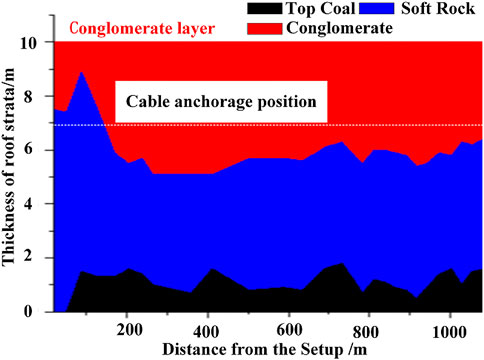
FIGURE 2. Geological condition of the 11301 service entry.
The roof sandy mudstone is analyzed by X-ray diffraction, and the specific test result is shown in Figure 3. The results of the sandy mudstone roof samples taken at the site show that the roof mudstone is mainly composed of Si/O/Al elements, and the mineral composition is mainly composed of these elements, such as quartz, montmorillonite, and illite. The quartz content in sandstone is relatively high, and the percentage of albite is less. The conglomerate layer is relatively thick, and the strength cannot be determined due to the difficulty in sampling. However, characteristics such as the difficulty in drilling and the lack of internal stratification during the drilling process indicate that the conglomerate strength is relatively high.
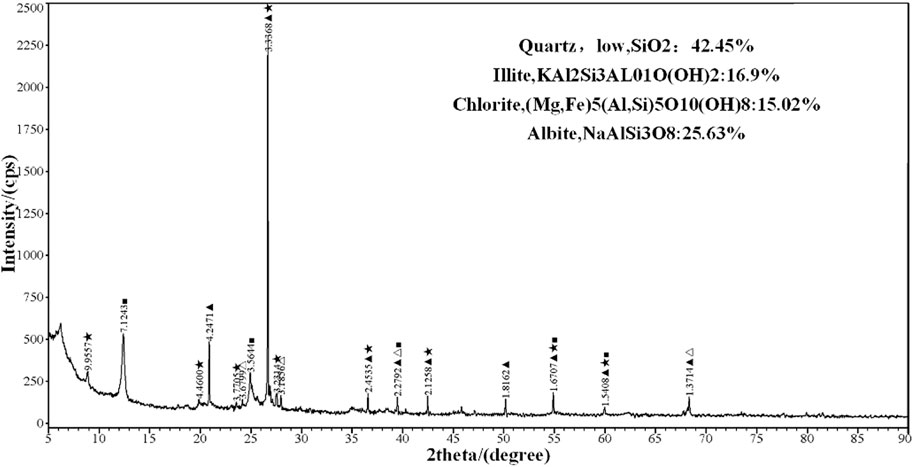
FIGURE 3. Composition spectrum of sandy mudstone.
This kind of rock disintegrates easily and weathers when exposed to water, and its cohesive property is relatively weak after exposure to water. The uniaxial compressive strengths of coal and sandy mudstone are 21.63 MPa and 17.45 MPa, respectively, as determined by basic mechanical testing. The difference between coal and rock strength is not obvious, and they both break into blocks under uniaxial compression. Sandy mudstone has low strength and poor bearing capacity and belongs to the category of weakly cemented soft rock.
3 Failure behaviors and corresponding failure mechanism
Under the stress of driving through the 11,301 service entry, some sections of the first 1000 m of the roadway were severely damaged. The deformation and failure can be divided into two types of failure behaviors: ①roof caving; ②roof cracks and fractures.
3.1 Mode Ⅰ: Roof caving
3.1.1 Failure behaviors
After some amount of traffic, the roof rock strata at 716–731 m of the 11,301 service entry caved, which was one time serving, as shown in Figure 4. The length of the caving area was 17 m, the full width of the roadway was caved (the width of the roadway is about 6 m), and the caving height was about 3.7 m. The caving position is consistent with the interface between the conglomerate layer and the sandy mudstone layer, and the caving volume is about 399.6 m3. The fallen gangue was broken, and a small part was powdery; there was no water pouring from the roof. The top coal is about 0.9 m thick at the roof of the roadway in this area. Where the roadway roof is sandy mudstone, the thickness is about 4.8 m; the upper part of the sandy mudstone is conglomerate with argillaceous cementation.
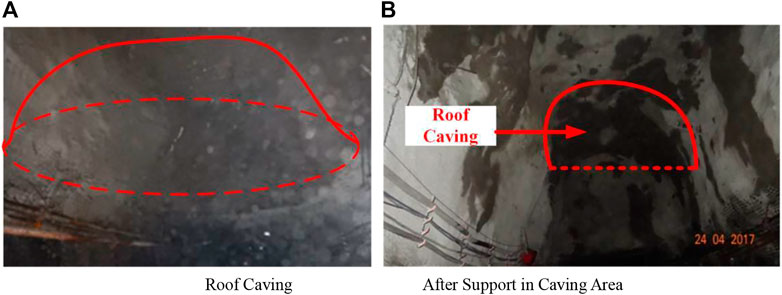
FIGURE 4. Roof housing of roadway, (A) roof housing, (B) After support in housing area.
According to the analysis of the field caving condition and the failure mode of the bolt and steel mesh, the rock strata first fell from the right side of the heading direction; that is, the roof of the pillar side first fell and then extended to the whole roof. At the same time, there were no broken bolts and cables on the surface of the gangue and caving roof, which indicated that most of the bolts and cables moved together with the roof, and some suspension cables showed that the integral support function of the cable was not good.
The poor condition of the surrounding rock of the roadway roof in this area is objective. Although the thickness of mudstone revealed by drilling on the roof of this area reaches 4.8 m, all sections of the roof may not be equally thick. At the same time, there is the phenomenon of the anchor cable being severed. The shortest anchor cable is only 3.6 m, indicating that the mudstone layer is relatively thin.
The initial supporting capacity of the roadway was analyzed: the roof was supported by anchor mesh cable, the diameter of the anchor cable was 17.8 mm, and the row and line space was 1.5 m × 3.0 m. The mining side used FRP anchor + plastic mesh, while the pillar side used screw steel anchor + metal mesh, as shown in Figure 5.
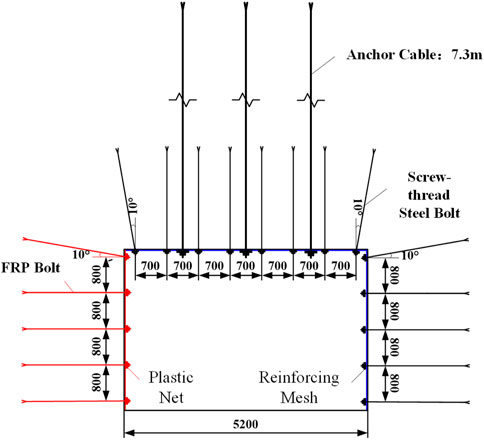
FIGURE 5. Support diagram.
3.1.2 Roof caving model
The roadway was left with a coal roof during driving, and the roof caving instability model was established, as shown in Figure 6. The cementation property of the roadway surrounding the rock is poor. Under the stress of traffic, cracks and separation are first generated at the junction of roof coal and mudstone and then extend upward and downward (Wang et al., 2020). After the roof mudstone fracture developed to a certain extent, it ran in the horizontal direction. The insufficient roadway support capacity resulted in the overall caving of the lower rock stratum due to its own weight.
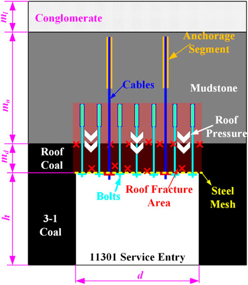
FIGURE 6. Schematic diagram of roof fractures area in the 11301 service entry.
3.1.3 Failure mechanism
3.1.3.1 Coal rock properties
The horizontal bedding in the middle of the coal seam showed vertical fractures, which is a typical double fracture structure. It was found on site that the strength of the mudstone layer was relatively low and fractured easily into large blocks. At the same time, the dislocation and stratification of mudstone were obvious, as shown in Figure 7.
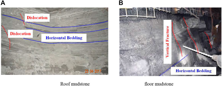
FIGURE 7. Characteristics of road mudstone, (A) roof mudstone, (B) floor mudstone.
3.1.3.2 Poor anchorage effect
The cementation of the roof conglomerate layer was poor, and the anchoring effect was poor when the anchor cable anchorage section was located in this area. The conglomerate layer was composed of gravel and sandy argillaceous cementation, in which the gravel was mainly quartzite and granite, with a particle size of 0.05–0.5 cm, locally reaching 0.8 cm, as shown in Figure 8. Drilling in the conglomerate layer revealed that the pore diameter varied substantially, and the sandy argillaceous cement turned to clay in the presence of water, which directly affected the adhesion of the anchorage agent and anchorage length, and then affected the anchorage and support quality of the anchor cable, resulting in roof caving.
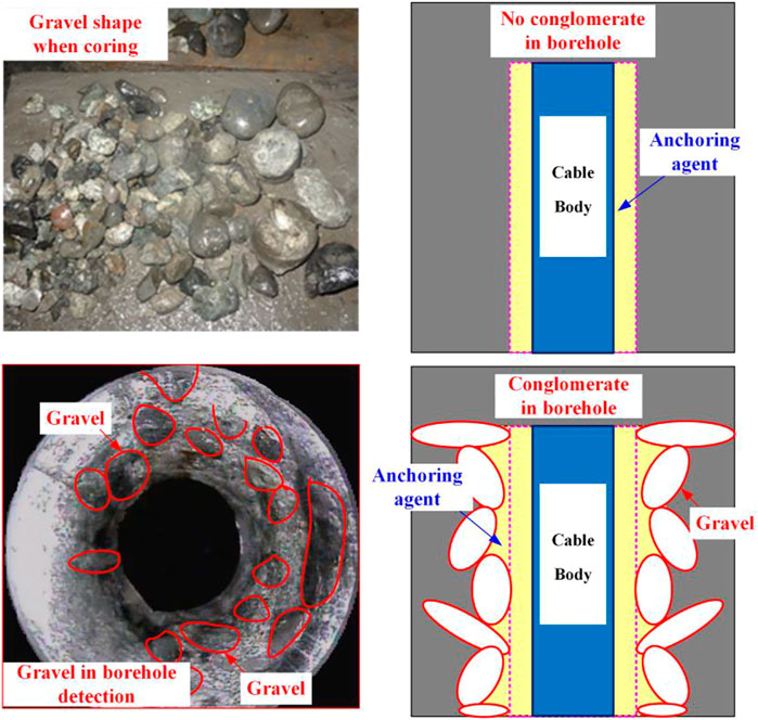
FIGURE 8. Anchorage characteristics of roof conglomerate area.
3.1.3.3 Insufficient support strength
The theoretical calculation method was used to calculate the thickness of the whole rock layer in the anchorage area (7.0 m) without considering the bolt support. Then, the range of the roof rock layer that can be controlled by the anchor cable can be obtained according to the following formula:
In the formula, D is the width of the control area of the anchor cable, S is the cable control area, RC is the design anchoring force of the cable, Lm is the thickness of the rock layer controlled by the anchor cable, and γm is the unit weight of rock stratum.
Therefore, a cable must be able to control a thickness of 7.0 m with an average unit weight of 20 KN/m3. When the designed anchoring force of the cable is 150 kN (using a 17.8-mm-diameter cable), the control area of the cable is 1.0×1.0 m. As originally installed, the bolt and cable support were not bear the weight of the roadway, which led to serious roof subsidence and even roof caving.
3.2 Mode Ⅱ: Roof cracks and fractures
3.2.1 Failure behaviors
In addition to roof caving, there were many roof cracks and roof fractures in different areas of the 11,301 service entry, as shown in Table 1.
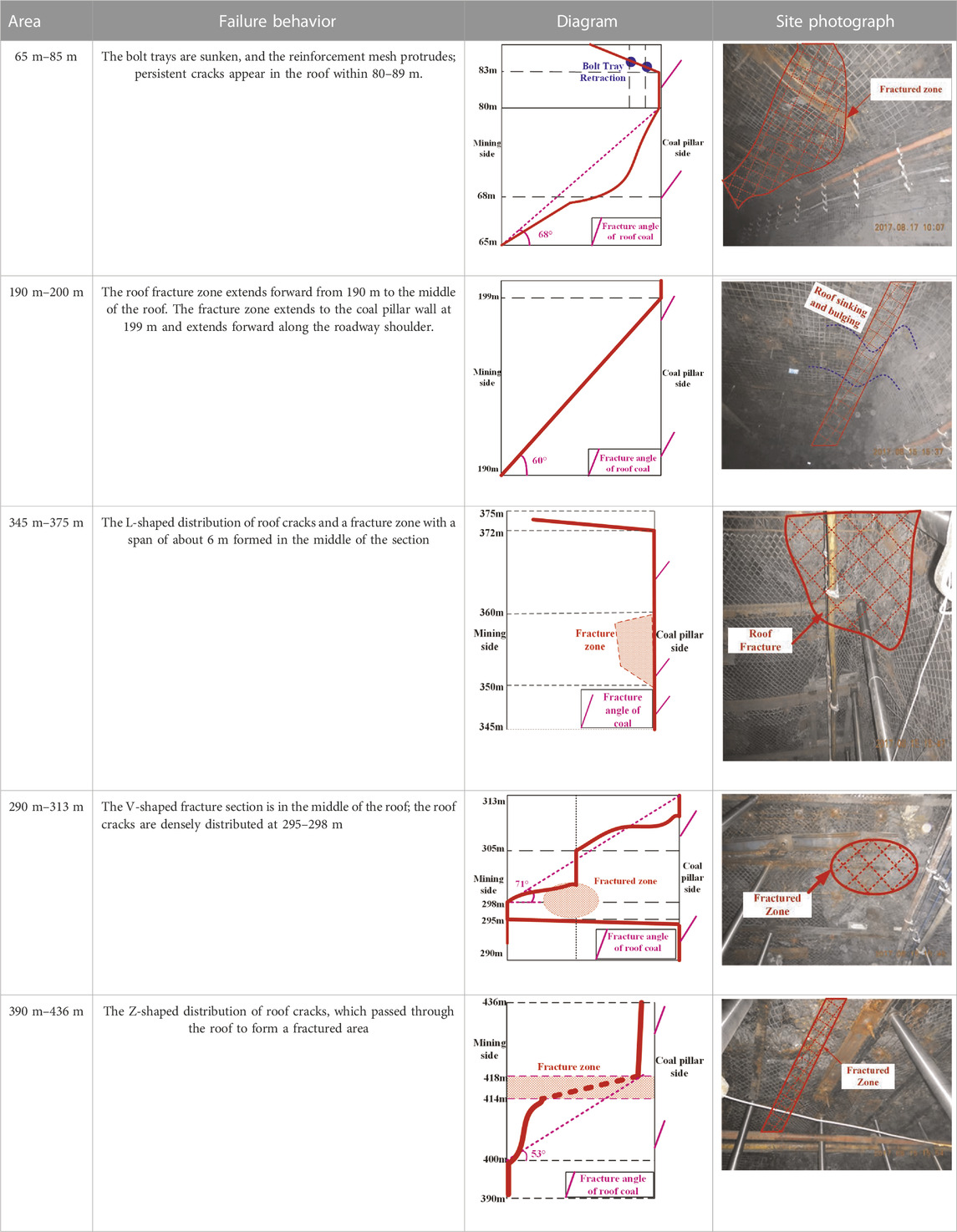
TABLE 1. Roof failure behaviors in different areas.
3.2.2 Roof fracture evolution
In order to explore the cause of roof fracture, borehole TV detection was carried out for the roof in this area, and the detection results are shown in Figure 9.
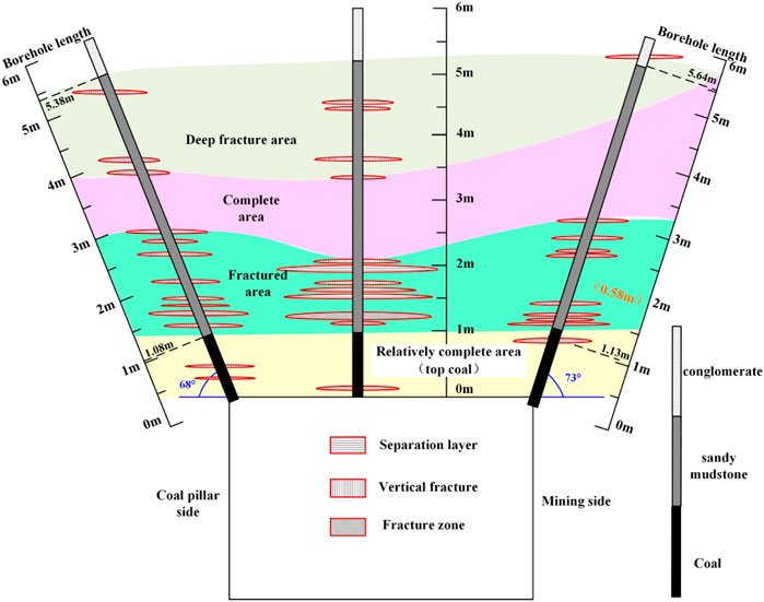
FIGURE 9. Monitoring results of roof crack distribution.
By analyzing the borehole TV results, the following conclusions are obtained.
① The roof failure area can be divided into a relatively complete area, a fractured area, a complete area, and a deep fractured area. The relatively complete area was mainly the thickness of top coal, about 1.0 m. The range of the fracture zone was about 1.0–2.5 m thick within mudstone, which belongs to the lower part of the mudstone layer. The complete area was located in the middle and upper part of the mudstone layer, with a thickness of about 0.5–2.5 m. The deep fracture zone was mainly located at the interface of the upper mudstone (with large thickness) and conglomerate.
② The roof failure area was mainly distributed in the rock stratum within the range of 1.0–3.5 m above the roof, especially when the thickness of the roof mudstone layer was small, the fracture area was obviously larger than the intact area. The fracture near the coal rock interface was more serious and extended to the upper mudstone layer, and there were relatively few fractures near the interface between the conglomerate and the mudstone.
According to the in-site observation of the roadway deformation and the borehole TV detection, the evolution of the roadway roof cracks was divided into the following four processes, as shown in Figure 10.
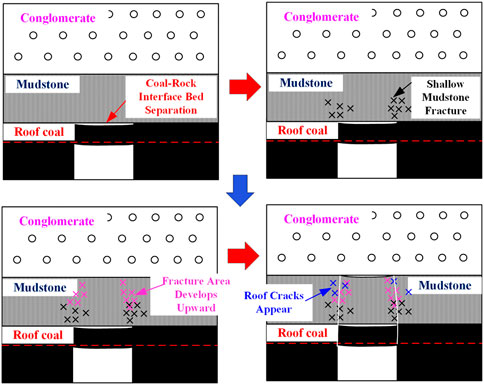
FIGURE 10. Schematic diagram of crack evolution in roof rock.
The reasons for cracks in some roof areas of the 11,301 service entry, especially at the two shoulders of the roadway, were as follows:
① Coal-mudstone interface bed separation. After excavation along the entry, the roof rock strata ruptured inside the roof coal and the lower area of the mudstone, and the roof coal fractures were mainly concentrated near the coal-rock interface. The length of the bolt was 2.4 m, and the thickness of the top coal was about 0.9–1.9 m. After the bolt was supported, the expansion of the rupture was limited by squeezing and strengthening. During this process, the pretension of the bolt and the actual anchoring force are very important.
② The shallow mudstone was fractured and developed upward. After the bed separation appeared, the shallow mudstone was broken first. As a result of the bolt support, with time, the new fracture and the expansion of the original fracture in the anchorage zone of the bolt are restrained to some extent. At this time, new fractures, bed separations, and vertical fractures began to appear in the deep part of the mudstone and continued to develop. At this stage, the main role of cables is to inhibit the generation and expansion of fractures, bed separations, and vertical fractures outside the anchor area.
③ Roof movement and subsidence. With the expansion of the roof coal and mudstone internal separation fracture, the serious external separation fracture at the anchoring end of the bolts made the bolts unable to inhibit the fracture, and the roof coal separation fracture continued to expand, causing the roof coal to move and sink. The moving subsidence could be divided into two cases: the lower part of the anchorage area moved and sank, and the whole anchorage area sank. In such a case, the reinforcement of the cable is important, especially for the latter condition.
④ Internal fracture and shear caving of coal and mudstone. With the continuous staggered subsidence of roof strata and the fracture penetration in the mudstone, the coal and mudstone above the roadway are under the control of the anchor cable, making it difficult for the anchor cable to support effectively, resulting in the cable breaking and subsequent roof instability. Finally, obvious cracks appeared in the roof and side of the roadway, and the original support effect was insufficient.
3.2.3 Failure mechanism
Because the mechanical properties of top coal and roof mudstone are similar, the top coal and mudstone are simplified as composite beam structures. Under its weight, the maximum stress in the composite beam formed by top coal and mudstone is:
In the formula, σmax is the maximum stress, M is the maximum bending moment, and Wc is the flexural section coefficient.
After the superposition of horizontal stress and vertical stress, the maximum stress in the composite beam becomes (Gu et al., 2012):
Among them, σ1max is the maximum stress of top coal, σ2max is the maximum principal stress of mudstone, q is the uniform load, h1 is the thickness of top coal, and h2 is the thickness of mudstone.
Because of the integrity of the composite beam, the curvature radius of the top coal and mudstone is the same, so the bending moment of roof strata can be obtained:
In this equation, M1 is the bending moment of top coal, M2 is the bending moment of mudstone, E1 is the elastic moduli of top coal, E2 is the elastic moduli of mudstone, I1 is the moment of inertia of top coal, I2 is the moment of inertia of mudstone, and b is the section width.
Therefore, the maximum stress in the range of top coal and mudstone can be obtained:
It can be seen from Formula 5 that the stress state of the roof is related to the strength parameters, such as the elastic modulus of the rock layer. Therefore, increasing the roof strength should be considered as a means of improving the robustness of the roadway.
4 Support optimization and application effect
4.1 General support principle
As mentioned previously, due to its weak cementation, the roadway roof first separates at the junction of coal and mudstone, then extends up and down. Targeted reinforcement measures should be taken according to the failure mechanism and stress state of the roof, as shown in Figure 11. The support range and capacity of the bolt and cable could not meet the requirements, leading to the roof caving. Optimizing the parameters of the bolt and cable can increase the thickness of the roof composite beam and improve the bearing capacity of the roof. The roof crack and failure situation, which used grouting reinforcement, requires that passive support schemes such as “single prop + top beam” be added.
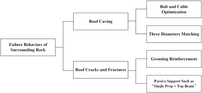
FIGURE 11. General support principle.
4.2 Roof caving: Optimization of bolt and cable support parameters
As a widely used support method, bolt and cable support play an obvious role in many geological conditions (Gabriel and Ihsan, 2016; Li et al., 2019; Zhao et al., 2021). Therefore, to prevent roof collapse, this paper optimizes the parameters of the bolt and cable. The bearing capacity and anchoring capacity of a 17.8-mm cable cannot meet the roof support requirements, so a 21.6-mm prestressed cable is used instead. The row and line spaces between cables were also changed from 1.5 m × 3.0 m to 1.5 m × 2.0 m. The condition of the anchor cable support and roof control before and after the support change is shown in Figure 12.
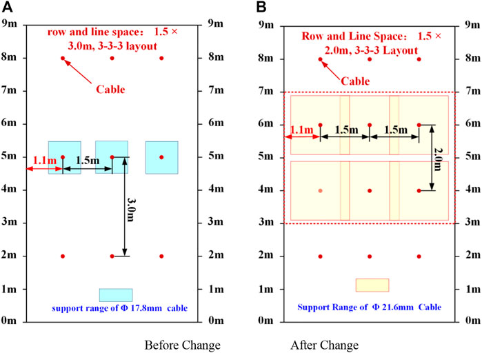
FIGURE 12. Schematic diagram of roof control before and after cable support change, (A) before change, (B) after change.
In addition to the row spacing between cables and other parameters, matching the diameters of the rod, drilling, and anchorage agent is also closely related to the system’s support capacity, as shown in Figure 13.
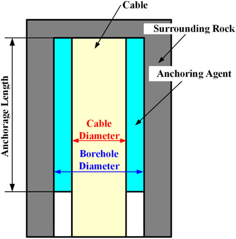
FIGURE 13. Schematic diagram of the rod diameter, drilling diameter, and anchorage agent diameter.
The quantitative relationship between rod diameter, borehole diameter, anchorage agent diameter, anchorage agent length, and anchorage length is shown in Formula 6.
In the formula,
After adjusting the support scheme, the diameter of the anchor cable is φ 21.6 mm. When different lengths of anchoring agents are adopted, the change of anchoring length is as follows.
① One strip of k2335# anchoring agent + two strips of k2360# anchoring agent. The cumulative length of the anchoring agent is 1.3 m, the diameter of the anchoring agent is 23 mm, and the diameter of the drilling hole is 32 mm. The calculated anchoring length is about 1.23 m.
② Two strips of k2380# anchoring agent. The cumulative length of the anchoring agent is 1.6 m, the diameter of the anchoring agent is 23 mm, and the diameter of the drilling hole is 32 mm. The calculated anchoring length is about 1.51 m.
Therefore, when the anchorage section of the anchor cable is located in the conglomerate layer, due to the influence of gravel, it is not only difficult to drill, but also the drilling diameter increases significantly, which reduces the anchorage length of the anchor cable and affects the anchorage effect. In the subsequent support scheme, the length or quantity of anchoring agent should be increased to achieve a better support effect.
After optimization of the roadway support scheme, the field test shows that the roof subsidence is improved, as shown in Figure 14.
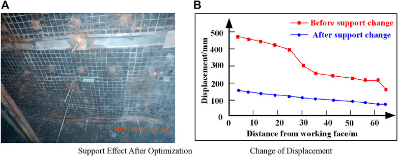
FIGURE 14. Roof support effect after support change, (A) support effect after optimization, (B) change of placement.
4.3 Roof cracks and fractures: Grouting + single prop + top beam
Grouting reinforcement can improve the bearing capacity of the rock layer itself, enhance the stability of the surrounding rock of the roadway (Xu and Hu, 2013; Aziz et al., 2017), effectively solve the more serious problem of roof fracture, and reduce the cracks and separation of the roof rock layer.
A deep and shallow grouting scheme was adopted, and grouting was applied every 3 m. The deep and shallow grouting holes were arranged at intervals. Five grouting holes were drilled in each deep row, with a spacing of 1.3 m. Three grouting holes were drilled in each shallow row, with a spacing of 2.5 m. The specific grouting scheme is shown in Figure 15.
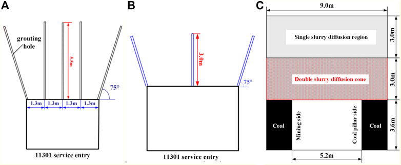
FIGURE 15. Routing scheme, (A) Layout of deep grouping hole, (B) Layout of shallow grouping hole, (C) Effective range of growing reinforcement.
After the grouting was completed, the roof was drilled for borehole imaging, and it was found that the filling effect at the 1.5–3 m depth of the roof was better in that the cracks were filled, but the shallow part of the roadway roof was not filled or not filled completely. The slurry filling is shown in Figure 16.
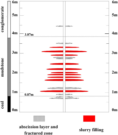
FIGURE 16. Condition of slurry filling.
The before- and after-grouting roof borehole observation results indicated that the filling rate of roadway roof cracks was only 55.6%, and the overall effect of grouting reinforcement was not sufficient. Therefore, a single column + top beam should be adopted for reinforcement and support of the collapsed roof area. A row of single props was set every 1 m, with three single props in each row, and a top beam was added above the props. The specific layout and the site conditions after support are shown in Figure 17.
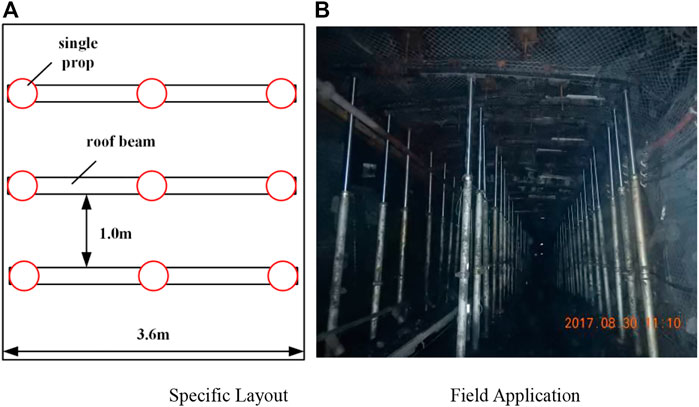
FIGURE 17. Single prop + top beam support, (A) Specific layout, (B) Field application.
Before the single prop + top beam support was adopted, the maximum displacement of the roadway roof and floor was 682 mm. After the single prop + top beam support was adopted, the maximum displacement was reduced to 108 mm, and the displacement of the roof and floor was reduced by 84.1%. The roadway stability was effectively improved through active grouting support and passive single prop + top beam support. After the combined reinforcement support, the roof subsidence was visibly restrained, which is a good engineering application effect.
5 Discussion
The deformation and failure of the surrounding rock of the weakly cemented soft rock roadway were obvious, and the determination and implementation of a support scheme became a key issue. Three kinds of support optimization schemes were formulated in this paper, according to various failure forms of a weakly cemented soft rock roadway, and field tests were carried out:
Through the optimization of anchor cable parameters and the field test of the single prop + top beam combined support, it was found that the two support methods are effective, which can significantly reduce the deformation of the roadway and inhibit roof subsidence and other mining phenomena. Testing the grouting reinforcement in the broken area revealed that the grouting effect was not good, mainly because the roadway roof slurry did not completely fill the cracks. Roof drilling detection shows that the shallow roof slurry was less distributed, perhaps because the grouting pressure of the roof was insufficient, resulting in the slurry being unable to distribute into the cracks.
The deformation and failure characteristics of the roadway roof were analyzed, and the occurrence of the roadway fracture zone was closely related to the change of roof crack direction. The location of the fracture area often occurs at the position where the fracture direction changes. It can be inferred that after the fracture direction changed, the rock fracture was more likely to occur at the intersection of the initial crack and the subsequent crack, which formed a fracture zone.
At present, experts and scholars have suggested several support schemes for weakly cemented soft rock roadway roof support, such as combined support control technology, double-layer long bolt mesh shotcrete and concrete-filled steel tubes, bolt-beam-net support, and U-shaped steel supports (Li et al., 2012; Meng et al., 2016; Wang et al., 2018; Li et al., 2020; Yu et al., 2020). Most of these deformation control methods are passive strong support Guo et al. (2015). Xiao et al. (2022) proposed the soft rock active support technology based on constant resistance using large deformation bolts and achieved good results. Based on the failure analysis, active or passive support methods are proposed in the aforementioned studies, but the support schemes are not sufficient. This paper suggests several support optimization measures designed for the characteristics of different failure areas of a weakly cemented soft rock roadway, including active support (optimization of bolt and cable parameters, grouting reinforcement) and passive support (single prop + top beam support). The experimental research into these measures has shown good field results.
In addition, the effect of the grouting reinforcement method proposed in this paper is not readily visible, so it is necessary to continue to optimize grouting parameters, such as grouting depth and grout strength, through numerical simulation and theoretical research, and then conduct a field test to select the best grouting scheme to achieve the expected purpose. At the same time, on the premise of poor active support effect, roadway deformation can be effectively improved through passive supports such as single prop + top beam. Therefore, a combination of reinforcement measures should be considered in the design or reinforcement of support schemes. When the effect of some measures is poor, other support schemes can play a better role.
6 Conclusion
(1) According to the scanning electron microscope results, roof rock with poor cementation easily disintegrates into mud when it meets water. The lithology of the roof is mainly weakly cemented soft rock. The main roof failure forms of the 11,301 service entry were roof cracks, concurrent roof fractures and cracks, and large-scale roof caving. Roof cracks and fracture areas appeared simultaneously, and there was roof subsidence in the roadway.
(2) The corresponding failure mechanisms of different roadway deformations and failure characteristics are analyzed. Different support optimization schemes, such as bolt and cable parameter optimization, grouting, and single prop + top beam, are proposed for the characteristics of the roof caving and fractured area.
(3) The field test results show that the optimized parameters of bolt and cable can meet the requirements of roadway roof support, and the grouting test results were not ideal, mainly because the roof crack filling effect was not good and did not have the expected control effect. However, after adding the passive support of a single prop and top beam, the roof subsidence has been well controlled.
Data availability statement
The raw data supporting the conclusion of this article will be made available by the authors, without undue reservation.
Author contributions
KZ wrote and structured the article. FY performed the on-site data collection and analysis. YT and TZ revised and adjusted the article. WG polished the article.
Funding
This work was supported by the National Natural Science Foundation of China (52074168 and 51974171) and the Climbing Project of Taishan Scholar in Shandong Province (No. tspd20210313).
Conflict of interest
The authors declare that the research was conducted in the absence of any commercial or financial relationships that could be construed as a potential conflict of interest.
Publisher’s note
All claims expressed in this article are solely those of the authors and do not necessarily represent those of their affiliated organizations, or those of the publisher, the editors, and the reviewers. Any product that may be evaluated in this article, or claim that may be made by its manufacturer, is not guaranteed or endorsed by the publisher.
References
Aziz, N., Majoor, D., and Mirzaghorbanali, A. (2017). Strength properties of grout for strata reinforcement. Procedia Eng. 191, 1178–1184. doi:10.1016/j.proeng.2017.05.293
Bi, J., Ning, L., Zhao, Y., Wu, Z., and Wang, C. (2023). Analysis of the microscopic evolution of rock damage based on real-time nuclear magnetic resonance. Rock Mech. Rock Eng., 1–13. doi:10.1007/s00603-023-03238-x
Bi, J., Tang, J. C., Wang, C. L., Quan, D., and Teng, M. (2022). Crack coalescence behavior of rock-like specimens containing two circular embedded flaws. Lithosphere Spec. 11, 9498148. doi:10.2113/2022/9498148
Du, S., Li, D., Yu, W., Zhang, J., and Liu, F. (2019). Stability analysis and support control for a jointed soft rock roadway considering different lateral stresses. Geotechnical Geol. Eng. 38 (1), 237–253. doi:10.1007/s10706-019-01013-w
Egger, P. (2000). Design and construction aspects of deep tunnels (with particular emphasis on strain softening rocks). Tunneling Undergr. Space Technol. 15 (4), 403–408. doi:10.1016/s0886-7798(01)00008-6
Gabriel, S. E., and Ihsan, B. T. (2016). Analysis of alternatives for using cable bolts as primary support at two low-seam coal mines. Int. J. Min. Sci. Technol. 26 (1), 23–30. doi:10.1016/j.ijmst.2015.11.005
Gu, S. C., Su, F., and Cui, X. P. (2012). Analysis on deformation and failure law of complex roof in seam gateway. Coal Sci. Technol. 40 (5), 20–23. doi:10.13199/j.cst.2012.05.24.gushch.014
Guo, Z. B., Wang, J., and Zhang, Y. L. (2015). Failure mechanism and supporting measures for large deformation of Tertiary deep soft rock. Int. J. Min. Sci. Technol. 25 (1), 121–126. doi:10.1016/j.ijmst.2014.11.002
Li, G., Ma, F. S., Guo, J., Zhao, H. J., and Liu, G. (2020). Study on deformation failure mechanism and support technology of deep soft rock roadway. Eng. Geol. 264, 105262. doi:10.1016/j.enggeo.2019.105262
Li, G. F., Wang, J. H., and Liu, J. R. (2022). Study on shear properties and failure characteristics of bolted joint of roadway surrounding rock. J. Shandong Univ. Sci. Technol. Sci. 41 (4), 47–55. doi:10.16452/j.cnki.sdkjzk.2022.04.006
Li, T., Shan, R. L., Han, H. S., Yang, W. H., and Liu, N. a. (2012). Mechanical mechanism and support design analysis on bolt-beam-net support in soft rock roadway in Qigou Coal Mine. J. Coal Sci. Eng. 18 (3), 247–253. doi:10.1007/s12404-012-0304-8
Li, T. C., Lu, Z., Liu, J. Z., and Ma, X. Q. (2014). Deformation and failure process analysis of rectangular roadway muddy weakly cemented soft rock strata. Rock Soil Mech. 35 (4), 1077–1083. doi:10.16285/j.rsm.2014.04.020
Li, Y., Liu, L., Sun, J., Li, Y., and Yan, X. (2019). Research on support of deformation of mining side gob along high-stress mining roadway. Geotechnical Geol. Eng. 37 (6), 5543–5553. doi:10.1007/s10706-019-00947-5
Lin, H. F. (2011). Study of soft rock roadway support technique. Procedia Eng. 26, 321–326. doi:10.1016/j.proeng.2011.11.2174
Liu, D. J., Zuo, J. P., Wang, J., Zhang, T. L., and Liu, H. Y. (2020). Large deformation mechanism and concrete-filled steel tubular support control technology of soft rock roadway-A case study. Eng. Fail. Anal. 116, 104721. doi:10.1016/j.engfailanal.2020.104721
Meng, Q. B., Han, L. J., Chen, Y. L., Fan, J. D., Wen, S. Y., Yu, L. Y., et al. (2016). Influence of dynamic pressure on deep underground soft rock roadway support and its application. Int. J. Min. Sci. Technol. 26 (5), 903–912. doi:10.1016/j.ijmst.2016.05.032
Song, D. Q., Liu, X. L., Huang, J., and Zhang, J. M. (2020). Energy-based analysis of seismic failure mechanism of a rock slope with discontinuities using Hilbert-Huang transform and marginal spectrum in the time-frequency domain. Landslides 18, 105–123. doi:10.1007/s10346-020-01491-7
Song, D. Q., Liu, X. L., Huang, J., Zhang, Y., Zhang, J., and Nkwenti, B. N. (2021). Seismic cumulative failure effects on a reservoir bank slope with a complex geological structure considering plastic deformation characteristics using shaking table tests. Eng. Geol. 286, 106085. doi:10.1016/j.enggeo.2021.106085
Song, D. Q., Liu, X. L., Li, B., and Zhang, J. M. (2021). Assessing the influence of a rapid water drawdown on the seismic response characteristics of a reservoir rock slope using time-frequency analysis. Acta Geotech. 16, 1281–1302. doi:10.1007/s11440-020-01094-5
Wang, H., Jiang, C., Zheng, P. Q., Li, N., and Zhan, Y. B. (2020). Deformation and failure mechanism of surrounding rocks in crossed-roadway and its support strategy. Eng. Fail. Anal. 116, 104743. doi:10.1016/j.engfailanal.2020.104743
Wang, H., Zheng, P. Q., Zhao, W. J., and Tian, H. M. (2018). Application of a combined supporting technology with U-shaped steel support and anchor-grouting to surrounding soft rock reinforcement in roadway. J. Central South Univ. 25 (5), 1240–1250. doi:10.1007/s11771-018-3821-9
Wang, Z., Yin, Y. C., and Zhao, T. B. (2021). Numerical simulation study on bolting mechanism and support control of soft rock roadway. J. Shandong Univ. Sci. Technol. Sci. 40 (3), 35–43. doi:10.16452/j.cnki.sdkjzk.2021.03.005
Xiao, P., Yu, H. Y., and Wang, D. (2022). Technology and application of active support replacing passivesupport in advance section of backfill mining. J. Shandong Univ. Sci. Technol. Sci. 41 (3), 41–49. doi:10.16452/j.cnki.sdkjzk.2022.03.005
Xu, Z., and Hu, M. (2013). Application of jet grouting reinforcement to tunneling in an Aeolian sand stratum. Mod. Tunn. Technol. 50 (3), 158–162. doi:10.13807/j.cnki.mtt.2013.03.018
Yu, K. P., Ren, F. Y., Puscasu, R., Lin, P., and Meng, Q. G. (2020). Optimization of combined support in soft-rock roadway. Tunn. Undergr. Space Technol. 103, 103502. doi:10.1016/j.tust.2020.103502
Zhang, D. B., and Zhang, Z. G. (2015). Anchor net spray and steel bracket combined supporting technology research on weakly cemented soft rock roadway. J. Liaoning Tech. Univ. 34 (4), 447–452. doi:10.11956/j.issn.1008-0562.2015.04.004
Zhao, T. B., Xing, M. L., Guo, W. Y., Wang, C. W., and Wang, B. (2021). Anchoring effect and energy-absorbing support mechanism of large deformation bolt. J. Central South Univ. 28 (2), 572–581. doi:10.1007/s11771-021-4622-0
Keywords: weakly cemented soft rock, surrounding rock failure, support optimization, field test, instability mechanism
Citation: Zhou K, Yu F, Tan Y, Guo W and Zhao T (2023) Study on failure behaviors and control technology of surrounding rock in a weakly cemented soft rock roadway: A case study. Front. Earth Sci. 11:1153753. doi: 10.3389/feart.2023.1153753
Received: 30 January 2023; Accepted: 20 March 2023;
Published: 25 May 2023.
Edited by:
Yunhui Zhang, Southwest Jiaotong University, ChinaCopyright © 2023 Zhou, Yu, Tan, Guo and Zhao. This is an open-access article distributed under the terms of the Creative Commons Attribution License (CC BY). The use, distribution or reproduction in other forums is permitted, provided the original author(s) and the copyright owner(s) are credited and that the original publication in this journal is cited, in accordance with accepted academic practice. No use, distribution or reproduction is permitted which does not comply with these terms.
*Correspondence: Fenghai Yu, eXVmZW5naGFpMjAwNkAxNjMuY29t