
95% of researchers rate our articles as excellent or good
Learn more about the work of our research integrity team to safeguard the quality of each article we publish.
Find out more
ORIGINAL RESEARCH article
Front. Earth Sci. , 02 March 2023
Sec. Environmental Informatics and Remote Sensing
Volume 11 - 2023 | https://doi.org/10.3389/feart.2023.1138925
This article is part of the Research Topic Coal and Rock Dynamic Disasters: Advances of Physical and Numerical Simulation in Monitoring, Early Warning, and Prevention View all 15 articles
 Xingpan Zhu1,2*
 Hu Wen1
In order to reveal the influence of air leakage on oxygen concentration in goafs of fully mechanized caving mining with a shallow buried and high mining height, the air leakage of No.122108 working face in Caojiatan coal mine in different seasons was tested by the SF6 tracer gas test method. Based on the result of the air leakage test, the “three zones” of spontaneous combustion in the goaf were simulated using Ansys Fluent fluid dynamics software, and the simulated result was compared with that of the field test. The result shows that the vertical air leakage of the working face is serious, the wind speed is high, and the air leakage rate is up to 86.96%. The air leakage rate is higher in winter and lower in summer. The air leakage intensity decreases from the air inlet side to the air return side through the middle of the goaf. The range of the oxidation heating zone of the goaf is 98–245 m on the air inlet side and 33–96 m on the air return side. The numerical simulation result is well consistent with the field test data. The research conclusion can guide fire prevention and the extinguishing of No.122108 working face and lay a foundation for the prevention and control of spontaneous fire in goafs of fully mechanized caving mining with a shallow buried and high mining height.
There are many kinds of complex mine disasters. coal spontaneous combustion is one of the most serious mine disasters (Querol et al., 2011; Liu et al., 2019; Zheng et al., 2019; Liu et al., 2020; Onifade and Genc, 2020; Jin et al., 2021; Kuai, 2021), which can easily cause casualties, environmental pollution, and property loss (Deng et al., 2017; Wu et al., 2018; Li et al., 2019; Song et al., 2020). According to the data, fire accidents caused by coal spontaneous combustion account for more than 90% of the total mine fires (Ma et al., 2022), and coal spontaneous combustion in goafs comprise over 60% of total mine spontaneous combustion (Su et al., 2016; Wen et al., 2017). In the process of mining, the roof of the coal bed in goafs will be pressed periodically; therefore, the roof will break and sink, and the cracks will be connected with goafs. For shallow buried coal beds, even the surface will experience local collapse, and rock cracks will penetrate the surface and goafs and form air leakage channels, thus creating air leakage and an oxygen supply environment for goafs (Li W. et al., 2022). When special geological conditions are encountered in the process of mining, the speed of mining slows down, and a certain thickness of the loose coal body is left behind in goafs, which will inevitably cause spontaneous combustion of coal left in goafs. Therefore, it is of great significance to study and master the distribution of air leakage flow fields in goafs of fully mechanized caving mining with a shallow buried and high mining height in order to realize the control of spontaneous combustion in goafs.
The SF6 tracer gas measurement method is a reliable technique for measuring air leakage in mines, which is used to determine air leakage channels and air leakage in goafs (Wang et al., 2014; Zhu et al., 2016). Researchers at home and abroad have carried out a lot of research studies and practices on air leakage using the SF6 tracer gas measurement method. Tian et al. (2020) measured the air leakage in goafs of the U-type ventilation working face in the Wenzhuang Coal Mine using the SF6 tracer gas method. The results showed that there were many air leakage channels in goafs of this working face, and the air leakage velocity at the interface between the hydraulic support and goafs was high. Zhao et al. (2016) used the SF6 tracer gas instantaneous release method to analyze the air leakage from surface cracks in the fully mechanized cave mining with a shallow buried and high mining height of the Pingshuo mine area, determining parameters of surface air leakage and proposing comprehensive prevention and control measures according to the air leakage test result. Wu (2020) used SF6 tracer gas measurement method to measure the air leakage velocity in the goaf of the Xiegou coal mining face and obtained the main air leakage interval of the goaf.
Due to the complexity of residual coal and porosity distribution in goafs, determining air leakage flow fields in goafs and “three zones” of spontaneous combustion in goafs by means of field measurement and experimental study is limited. To some extent, numerical simulation can make up for the deficiency of field measurement and carry out reasonable and accurate physical simulation of air leakage flow fields in goafs (Kurnia et al., 2014; Tang et al., 2016; Zhang and Ji, 2016; Liu et al., 2022). Based on the unsteady state simulation method, Zuo et al. (2021) divided “three zones” of coal spontaneous combustion in goafs by analyzing the relationship between working face mining and coal spontaneous combustion under the condition of low air leakage velocity in goafs. Li et al. (2019), by establishing a numerical model, determined the three-dimensional spontaneous combustion risk area in goafs. The results showed that the “spontaneous combustion zones” in goafs became wider along the vertical height and the spontaneous combustion risk area turned larger. Shi et al. (2014) simulated the variation law of oxygen concentration in goafs during the mining of a fully mechanized caving mining face by the computational fluid dynamics (CFD) method. Hu and Liu (2021) took a fully mechanized caving mining face in the Yindonggou Coal Mine as the research object and combined numerical simulation with actual conditions to accurately divide the distribution range of “three zones” of spontaneous combustion in goafs. The simulation result was in agreement with the measured one. Based on the method of numerical simulation and field measurement, Xing (2021) studied the influence of surface air leakage in shallow thick coal beds on coal spontaneous combustion in goafs and obtained the distribution of “three zones” in goafs and the distribution law of the oxygen concentration field. In addition, a coal mine fire monitoring device was used for field verification.
At present, most scholars have only studied the law of air leakage in one time dimension. Due to the change of seasons, many environmental factors such as climate, temperature difference, and atmospheric pressure are changed, which causes the coal seam to trigger the “gasp effect.” Based on the research studies carried out at home and abroad, this study takes No.122108 working face of Caojiatan coal mine as the research object and uses the SF6 tracer gas to measure the air leakage of this working face in summer, autumn, winter, and spring. Based on the measured result of the air leakage, fluid dynamics software Ansys Fluent is used to simulate the “three zones” of spontaneous combustion in goafs, and the simulation result is compared with the field measurement. The research conclusion can lay a foundation for the prevention and control of spontaneous fire in goafs of fully mechanized caving mining with a shallow buried and high mining height. It is hoped that it can guide the fire prevention and extinguishing work of a similar working face in Caojiatan coal mine.
The subsequent sections of this paper are organized as follows: Section 2 introduces the overview of the working face. Air leakage measurement of the SF6 tracer gas and analysis of results are elaborated in Section 3. Section 4 is dedicated to the theoretical basis of simulation in the goaf, parameter setting of the numerical model of the goaf, and the numerical simulation result and analysis. Field verification is explained in Section 5. Finally, conclusions are given in Section 6.
No. 122108 working face is located in the second coal face in the east of the 12th panel of the 2–2 coal bed in Caojiatan coal mine, and the mined coal bed belongs to the type I spontaneous combustion coal bed. The coal dust is explosive with the absolute gas emission of 2.90 m3/min and relative gas emission of 0.10 m3/t. The working face is adjacent to the goaf of No.122106 working face in the north, with a strike length of 5,966 m and an inclined length of 280 m. The working face adopts the longwall backward mining method and integrates the fully mechanized caving mining technology. The caving method is used to treat the goaf. The average coal thickness of the working face is 10 m, the designed mining height is 6 m, the coal caving height is 4 m, and the ratio of mining to caving is 1:0.67. The coal mining machine cuts coal in two directions, and the end is cut obliquely with a length not less than 59.7 m and a depth of 865 mm. The roadway layout of the mining working face is shown in Figure 1.
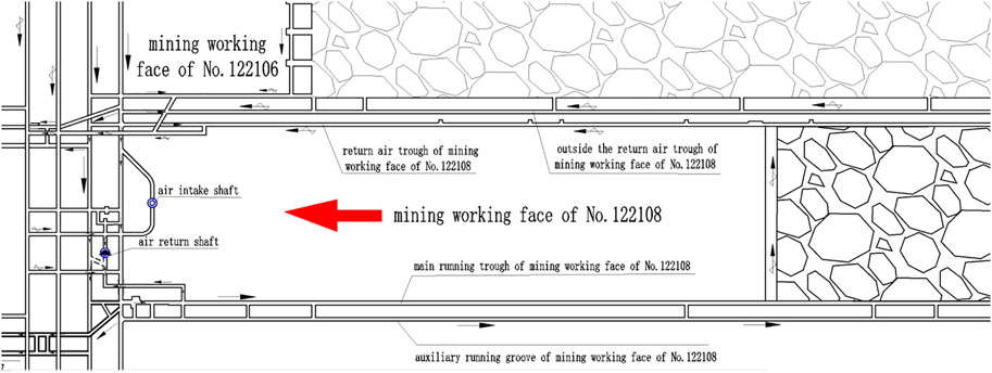
FIGURE 1. Roadway layout of the mining working face.
SF6 does not exist in natural stones and has good stability and testability (Zheng et al., 2022). Therefore, this study uses the SF6 tracer gas to detect the air leakage. When there is an air leakage channel, SF6 will pass through and can be detected at the air outlet; otherwise, it must not be detected from the air return side.
This study measures the distribution of surface air leakage channels by the SF6 tracer gas pulse release method and tests surface air leakage of No.122108 working face in spring, summer, autumn, and winter in situ. In order to ensure the accuracy and reliability of the field test, this paper measures twice a quarter. This study measures the SF6 gas released from the surface, which is tested, and the air return corner of the working face is measured to analyze the distribution law of air leakage channels on the surface and the air leakage and transfusion parameters.
The vertical air leakage rate from the surface to the goaf is calculated quantitatively by the release time of the tracer gas on the surface, the appearance time of the tracer gas in the mine, and the relative position between the release point and the working face. The air leakage rate can be expressed as follows (Tian et al., 2022):
where V is the air leakage rate, d is the distance between the tracer gas release point and the corner of the working face, and t refers to time interval.
Due to irregular air flow to the formation in cracks, the maximum air leakage rate and the minimum air leakage rate can be determined by calculating the longest and shortest straight line distances, respectively. As shown in Figure 2, the formula for calculating the maximum and minimum air leakage rates can be obtained as follows.
where Vmax and Vmin are the maximum and minimum air leakage rates, respectively.
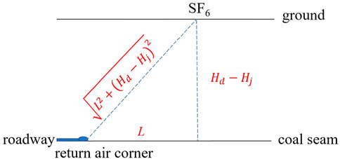
FIGURE 2. Schematic diagram of air leakage rate calculation (L is the horizontal distance between the tracer gas release point and the working face, and Hd and Hj represent the elevation of the tracer gas release point and monitoring point in the mine, respectively).
In this measurement, the instantaneous release mode is adopted to conduct field observation and investigation on the surface subsidence area of the working face at different times (winter: 16 January 2021; spring: 11 March 2021; summer: 27 June 2021; and autumn: 16 September 2021). In addition, a “two-way” chute with a relatively large air leakage and good communication with the working face and the position with large cracks under periodic pressure of the working face are selected as tracer gas release points on the surface. The SF6 tracer gas is used to test the distribution of surface air leakage channels, and the release amount is 32 L. The selected release point position is shown in Figure 3.
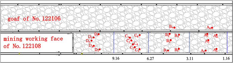
FIGURE 3. SF6 release point position (A, B, C, and D represent winter, spring, summer, and autumn, respectively. The numbers 1 to 6 represent the position of the SF6 tracer gas measuring point).
The portable SF6 gas detector is adopted to test the return wind 20 m from the return wind corner of No.122108 working face on the surface and in the mine in different seasons. The ambient temperature, air pressure, working face wind speed, SF6 appearance time, and duration are recorded, and then the air leakage from the surface to No.122108 working face is measured.
As can be observed in Figures 4, 5, the largest temperature difference in winter reaches 37.7°C, the surface temperature is below zero, and the smallest temperature difference in summer is only 0.9°C. Because of the change of seasons, the surface temperature is greatly different, and the change of air temperature leads to the change of air density, forming the phenomenon that the atmospheric pressure in winter is higher than that in summer. The downhole is a semi-closed environment where the change of temperature and atmospheric pressure is small, thus forming an evident temperature difference in the downhole. As shown in Figure 5, the maximum air pressure difference is 40.37 hPa in winter and 22.47 hPa in summer. The difference between spring and autumn is small due to climatic characteristics.

FIGURE 4. Change of surface and downhole temperatures in different seasons.
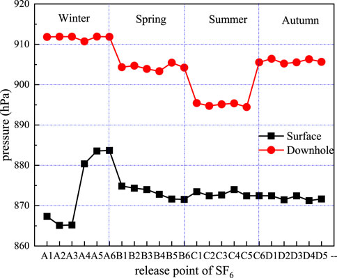
FIGURE 5. Change of surface and downhole air pressures in different seasons.
In combination with the crack survey in the surface collapse area, tracer gas release in different positions, and downhole observation, the vertical air leakage in No.122108 working face of Caojiatan coal mine is qualitatively and quantitatively analyzed to find the characteristics and law of the formation of surface cracks and air leakage channels. The change of the air leakage rate of each measuring point in different seasons is obtained by calculation, as shown in Figure 6. The result shows that the vertical air leakage of No.122108 working face in Caojiatan coal mine is serious, the wind speed is high, air leakage exists in 20 of 23 measuring points, and the air leakage rate is up to 86.96%. As can be observed in Figure 6, the air leakage rate also varies significantly with the seasonal change. Due to the large temperature difference in winter, the air pressure difference between the surface and downhole is large, the air leakage is serious, and the maximum air leakage rate at A5 measuring point reaches 0.1614 m/s. The air leakage rate is generally higher in winter than in the other three seasons, and the air leakage rate is the lowest in summer because the temperature in winter is low, the air shrinks, the density increases, and the weight of the air column per unit area and the air pressure goes up. Therefore, in winter, the maximum air leakage rate ranges from 0.1003 to 0.1614 m/s, the average flow rate is 0.1022 m/s, the minimum air leakage rate is 0.0717–0.1145 m/s, and the average flow rate is 0.5377 m/s. It is the opposite in summer. The air pressure decreases, and the downhole negative pressure decreases. In summer, the maximum air leakage rate ranges from 0 to 0.1354 m/s, the average flow rate is 0.0961 m/s, the minimum air leakage rate ranges from 0 to 0.0983 m/s, and the flow rate is 0.0670 m/s. Seasonal changes result in the difference of pressure between the surface and downhole, and the air leakage is serious in winter when the negative pressure increases.
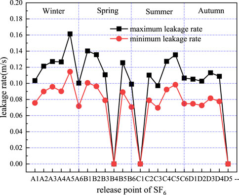
FIGURE 6. Change of the air leakage rate at each release point in different seasons.
Figure 7 shows the change of the average air leakage rate with the working face distance. It can be observed that the air leakage rate is smaller when the measuring point is far away from the working face. On the contrary, the air leakage rate is larger when the distance from the working face is closer. This is because the surface cracks at the measuring point far away from the working face are relatively few due to a series of environmental factors such as long subsidence time and surface soil filling, and the wind leakage speed of the cracks is relatively small; the surface cracks at the measuring point near the working face are relatively more for a good development condition due to the initial formation of the subsidence area, and the wind leakage speed of the cracks is relatively large. According to the results of field investigation and test, the transfusion through the surface to the goaf is not uniform due to serious air leakage in the large crack zone in some subsidence areas and the small cracks with little or no air leakage. There are many extended large cracks on the surface; the maximum width of cracks is 0.03–0.09 m, and the length of cracks is 23–35 m. These large cracks are highly likely to have serious air leakage and need to be buried in time.
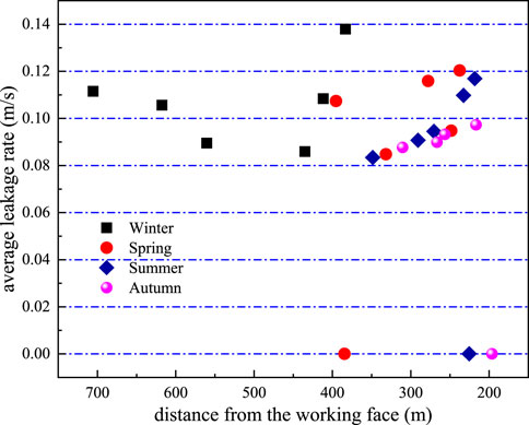
FIGURE 7. Change of the average air leakage rate with the working face distance.
Figure 8 shows the distribution of the average air leakage flow rate on the air inlet side, air return side, and measuring point in the middle of the working face in four seasons. It can be observed that the air leakage flow rate on the inlet side is relatively large, while that on the return side is relatively small.
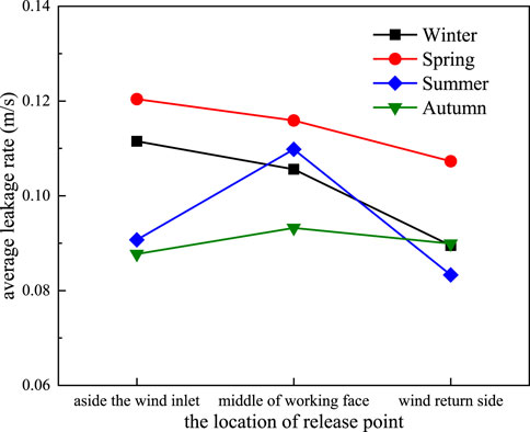
FIGURE 8. Distribution of the average air leakage flow rate of the measuring points at different positions in the surface crack working face in four seasons.
The main methods for calculating the air leakage intensity of a loose coal body include the air flow calculation method, Darcy differential algorithm, air network solution algorithm, and oxygen concentration calculation method (Deng et al., 1999). Theoretically, the first three methods can accurately calculate the air leakage intensity and distribution of a loose coal body. However, due to the limitation of accuracy of the current wind and pressure measurement technology and practical conditions of roadway, it is difficult to implement the practical application of calculating the air leakage intensity of a loose coal body. The error is large, so they are seldom used in the field. The fourth method is simple and accurate; it calculates the air leakage intensity using the measured oxygen concentration.
The oxygen concentration measurement method is through the actually measured oxygen concentration distribution to push back the air leakage intensity. The idea is to assume a kind of air leakage law and calculate the air leakage intensity according to the oxygen consumption rate of coal at the temperature by measuring the oxygen concentration at a certain point in a loose coal body. The air leakage intensity is taken as the initial value, and the change of the system air pressure is considered (mainly the change of hot air pressure caused by the change of coal temperature); then, the dynamic change law of air leakage intensity can be obtained.
Assuming that the air leakage flows only along one dimension, when the air leakage intensity in a loose coal body is constant, the relationship between the air leakage intensity and oxygen concentration can be obtained [as shown in Formula 4 (Zuo et al., 2018)]:
where
According to the field observation data, the horizontal distribution map and three-dimensional distribution map of the air leakage intensity in different positions inside the goaf are established as shown in Figures 9, 10. As can be observed in Figures 9, 10, the air leakage intensity is highest on the air inlet side of the goaf, second highest in the middle of the goaf, and lowest on the air return side. Therefore, the air leakage intensity decreases from the air inlet side to the air return side through the middle of the goaf. At about 50 m from the air inlet side to the working face, the air leakage intensity has a peak value and is higher than the surrounding points, which should be due to the existence of the auxiliary chute and connection roadway at the wind inlet side so that the air leakage is relatively large. According to the analysis result of air leakage intensity, the air leakage is serious on the air inlet side, which should be the key area of fire prevention and extinguishing work.
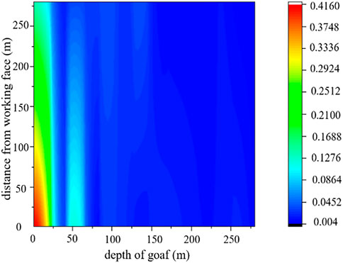
FIGURE 9. Distribution of the air leakage intensity of No.122108 working face.
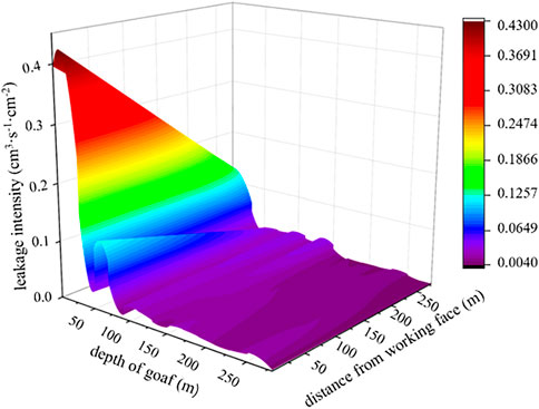
FIGURE 10. Three-dimensional distribution map of the air leakage intensity of No.122108 working face.
After the working face is mined, the roof strata will collapse one after another. Therefore, the goaf is filled with broken rock and the loose coal body, and the cracks between the broken rock and the loose coal body are very abundant in the goaf. For the purpose of simulation calculation, we consider the loose coal body and rock as homogeneous porous media. It is assumed that 1) spontaneous combustion occurs in residual coal in the goaf; 2) heat exchange occurs between residual coal and the surrounding air; and 3) heat released by the chemical reaction enhances the transfusion process between the substances and intensifies heat and mass transfer.
The pore distribution in loose coal is usually large, and large pores will cause the gas to leak easily. The air leakage rate causing spontaneous coal combustion is very small (0.001–0.5 cm s-1) under the actual conditions, and the air leakage distribution is a function of time and space. In order to study the influence of surface air leakage on coal spontaneous combustion in the goaf, the control equation of the key characteristic parameter O2 of coal spontaneous combustion is established.
The migration of O2 in porous media includes diffusion and transfusion. According to Fick’s law, the diffusion of air components is from high concentration to low concentration. In the given calculation area, O2 transfusion should conform to Darcy’s law, and the air leakage intensity in the transfusion model only needs to consider the air leakage through the unit area of loose coal. The equation for the mass balance of O2 can be expressed as follows:
where
In the normal production of the mine, it is assumed that the transfusion, diffusion, and chemical reaction in the combustion space proceed smoothly, and the total mass of air remains unchanged. If the temperature of the goaf is basically kept constant, the governing equation of the flow field in the goaf can be obtained as follows (Li Y. C. et al., 2022):
where H is the pressure and k is the absolute permeability; if the permeability of the goaf is isotropic, kx=ky=kz; µ is the air viscosity coefficient; C0 is the mass concentration of O2 in air; V0(T) is the standard oxygen consumption rate.
In accordance with the actual condition of No.122108 working face, a three-dimensional model of the goaf of the working face is established. The depth of the goaf is set to 400 m, the inclined length of the working face is set to 280 m, the thickness of floating coal along the inlet and return air chute is set to 5.71 m, the thickness of floating coal in the middle of the goaf is 0.85 m, and the rock on floating coal is 10-m thick. The origin of coordinates is located at the innermost end of the goaf. The direction pointing to the air outlet is the x-axis-positive direction, the direction pointing to the working face is the y-axis-positive direction, and the upward direction is the z-axis-positive direction. The calculation area grids are divided into structured grids. In the floating coal, the step length is 1 m in x, y, and z directions, the step length in the rock is 4 m, and there are 1,523,756 grids. The three-dimensional model and grid division are shown in Figures 11, 12.
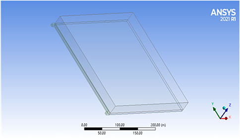
FIGURE 11. Three-dimensional model of the goaf.
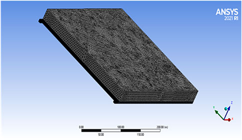
FIGURE 12. Three-dimensional model of grid division.
The setting of boundary conditions is the key of the numerical simulation solution. Only when the conditions are reasonable and close to the actual conditions can the accurate flow field distribution be calculated.
In the model area studied, it is assumed that the air inlet lane, air return lane, and working face surface are boundaries in this area. The wind speed and gas concentration involved in these boundaries are the boundary conditions to be considered in the model. In addition, it is assumed that that rest of the surface in the area has a wall property. Due to the presence of this wall, the permeation effect of the gas will not be possible. Therefore, based on the aforementioned assumptions, the boundary conditions for transfusion and diffusion in the model area are defined as follows.
(1) Assuming that the temperature in the goaf does not change and the pressure at both ends of the working face remains stable, it is a steady-state transfusion problem, namely,
(2) On the wall,
Assuming that the gas enters the goaf in a steady-state transfusion mode, the air inlet is set to the velocity inlet, the speed is set to 2.4 m/s, and the air outlet boundary is set to out flow. The goaf is set as the porous medium area of air flow. The porosity, viscous resistance coefficient, inertia resistance coefficient, and oxygen consumption rate are compiled into the solution program by UDF programming. In that process of model solution, the energy equation and the component transport model are opened.
Based on the aforementioned model, the distribution of oxygen concentration in the goaf is obtained as shown in Figure 13. Figures 13A, B show, respectively, smooth distribution and stripe distribution of oxygen concentration at a distance of 0.5 m from the coal seam floor, and Figure 13C shows three-dimensional distribution of the oxygen concentration in the goaf.
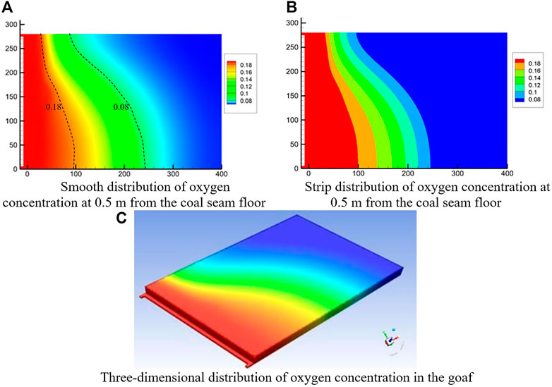
FIGURE 13. Distribution of oxygen concentration in the goaf. (A) Smooth distribution of oxygen concentration at 0.5 m from the coal seam floor. (B) Strip distribution of oxygen concentration at 0.5 m from the coal seam floor. (C) Three-dimensional distribution of oxygen concentration in the goaf.
It can be observed from Figures 13A–C that oxygen concentration in the goaf of Caojiatan coal mine is 18% at 98 m from the air inlet side to the working face and 8% at 245 m; similarly, oxygen concentration on the air return side is at 33 and 96 m. The comparison shows that oxygen concentration on the air inlet side of the goaf decreases more slowly than that on the air return side, oxygen concentration distribution at the same depth is different, and oxygen concentration at the inlet side is greater than that at the return side.
The oxygen concentration result obtained by the simulation is compared with the field observation result as shown in Figures 14, 15.

FIGURE 14. Comparison of measured and simulated oxygen concentration on the air inlet side.

FIGURE 15. Comparison of measured and simulated oxygen concentration on the air return side.
As can be observed intuitively from Figures 14, 15, the oxygen concentration data obtained by numerical simulation show a decreasing trend as a whole along with the extension of the deep part of the goaf, while the measured data show a slight fluctuation and decreasing trend. This is due to the error in field measurement and the influence of air leakage in the goaf. Generally speaking, the numerical simulation and the field data are well anastomotic. Considering the results of field observation and simulation, in order to eliminate the hidden danger of coal spontaneous combustion in the goaf of coal spontaneous combustion fully mechanized caving face, it is necessary to enlarge the monitoring range of the dangerous area in the goaf. Therefore, assuming that the thickness of floating coal is enough to gather heat, it can be preliminarily judged that the coal spontaneous combustion risk is high in the goaf of No.122108 fully mechanized caving face in Caojiatan coal mine in the range of 98–245 m from the air inlet side and 33–96 m from the air return side.
This study takes No.122108 working face of Caojiatan coal mine as the research object and uses the SF6 tracer gas to measure the air leakage of the working face in different seasons. Based on the result of air leakage measurement, the “three zones” of spontaneous combustion in the goaf are simulated using Ansys Fluent fluid dynamics software, and the simulation result is compared with the field measurement. The main conclusions are as follows.
(1) The vertical air leakage in No.122108 working face is serious, with high wind speed and air leakage rate up to 86.96%. The air leakage intensity decreases from the air inlet side to the air return side through the middle of the goaf.
(2) The air leakage rate of No.122108 working face is generally higher in winter than that in other three seasons and the lowest in summer. When the measuring point is far away from the working face, the air leakage rate is small, and when the measuring point is near the working face, the air leakage rate is large.
(3) The oxygen concentration in the goaf of No.122108 fully mechanized caving face is 18% at 98 m on the air inlet side and 8% at 245 m and 33 and 96 m on the air return side, respectively. The decrease speed of oxygen concentration on the intake side of the goaf is slower than that on the return side. The oxygen concentration distribution at the same depth is different and that on the inlet side is greater than that on the return side.
(4) The numerical simulation and the field data are well anastomotic. In order to eliminate the hidden danger of coal spontaneous combustion in the goaf of No.122108 fully mechanized caving face, it is necessary to enlarge the monitoring range of the dangerous area in the goaf.
The raw data supporting the conclusion of this article will be made available by the authors, without undue reservation.
Investigation, methodology, and writing-original draft were completed by the author XZ. Formal analysis, supervision, and final draft were completed by the author HW.
Author XZ was employed by the company Shaanxi Coal and Chemical Industry Group Co., Ltd., Yubei Coal Industry.
The remaining author declares that the research was conducted in the absence of any commercial or financial relationships that could be construed as a potential conflict of interest.
All claims expressed in this article are solely those of the authors and do not necessarily represent those of their affiliated organizations, or those of the publisher, the editors, and the reviewers. Any product that may be evaluated in this article, or claim that may be made by its manufacturer, is not guaranteed or endorsed by the publisher.
Wu, W. Q. (2020). Three zones fire prevention and extinguish technology for fully mechznized caving face of Gaoyang Coal Mine. Shanxi Coking Coal Sci. Technol. 44(9), 23-26–26.
Deng, J., Xu, J. C., Wang, C. Y., and Lv, Z. Q. (1999). Methods for calculating specific air-leakage in loose coal of fully mechanized longwall top-coal caving face. J. China Coal Soc. 24 (5), 502–506. doi:10.13225/j.cnki.jccs.1999.05.014
Deng, J., Li, B., Xiao, Y., Ma, L., Wang, C. P., Wang, B. L., et al. (2017). Combustion properties of coal gangue using thermogravimetry- Fourier transform infrared spectroscopy. Appl. Therm. Eng. 116, 244–252. doi:10.1016/j.applthermaleng.2017.01.083
Hu, J. T., and Liu, Z. G. (2021). Numerical simulation of spontaneous combustion “Three zones” in goaf of Yindonggou 110201 fully mechanized working face based on FLUENT. Coal Technol. 40 (8), 111–115. doi:10.13301/j.cnki.ct.2021.08.028
Jin, Y. F., Yan, L., Liu, Y., and Li, C. S. (2021). The spatiotemporal changes of oxygen consumption rate and heat release intensity during coal spontaneous combustion. Int. J. Heat Technol. 39 (4), 1287–1293. doi:10.18280/ijht.390427
Kuai, D. L. (2021). Distribution law of three spontaneous combustion zones in the goaf area of a fully mechanized working face under high ground temperature. Environ. Earth Sci. Res. J. 8 (2), 86–90. doi:10.18280/eesrj.080204
Kurnia, J. C., Sasmito, A. P., and Mujumdar, A. S. (2014). CFD simulation of methane dispersion and innovative methane management in undergroundmining faces. Appl. Math. Model. 38 (14), 3467–3484. doi:10.1016/j.apm.2013.11.067
Li, C. Y., and Zhang, L. L. (2019). Study on distribution law of spontaneous combustion “three zones” in goaf of fully mechanized mining face with large mining height. IOP Conf. Ser. Earth Environ. Sci. 358, 032041. doi:10.1088/1755-1315/358/3/032041
Li, J. L., Lu, W., Cao, Y. J. Z., Kong, B., and Zhang, Q. S. (2019). Method of pre-oxidation treatment for spontaneous combustion inhibition and its application. Process Saf. Environ. Prot. 131 (C), 169–177. doi:10.1016/j.psep.2019.08.013
Li, W., Qiang, F. W., Yang, C. F., and Quan, Y. P. (2022). Numerical simulation study on “three zones” of spontaneous combustion in goaf of fully mechanized mining face. Shaanxi Coal 4, 38–42.
Li, Y. C., Huang, Y. L., Wu, Y. B., Guo, Y. C., Sun, T. Y., Liu, Y. H., et al. (2022). Study on the development law of surface cracks in extra-thick coal seam mining in Loess Gully region. Min. Res. Dev. 42 (6), 68–73. doi:10.13827/j.cnki.kyyk.2022.06.030
Liu, W. Y., Wen, H., and Guo, J. (2019). Inhibition mechanism of LDHs on coal spontaneous combustion based on thermogravimetric analysis. Int. J. Heat Technol. 37 (2), 589–596. doi:10.18280/ijht.370229
Liu, Y., Wen, H., Guo, J., Jin, Y. F., Wei, G. M., and Yang, Z. W. (2020). Coal spontaneous combustion and N2 suppression in triple goafs: A numerical simulation and experimental study. Fuel 271, 117625. doi:10.1016/j.fuel.2020.117625
Liu, Z. Z., Jiang, S., Tian, B., Zhu, K., and Lin, W. H. (2022). Mining subsidence monitoring based on InSAR method fusing multi-threshold target. Acadlore Trans. Geosci. 1 (1), 22–32. doi:10.56578/atg010104
Ma, L. Y., Zhang, Y. L., Wang, J., Wang, J. F., and Zhou, C. S. (2022). Fire-prevention characteristics of an active colloid prepared from stimulated fly ash component. ACS Omega 7, 1639–1647. doi:10.1021/ACSOMEGA.1C03299
Onifade, M., and Genc, B. (2020). A review of research on spontaneous combustion of coal. J. Min. Sci. Technol. Engl. Ed. 30 (3), 303–311. doi:10.1016/j.ijmst.2020.03.001
Querol, X., Zhuang, X., Font, O., Izquierdo, M., Alastuey, A., Castro, I., et al. (2011). Influence of soil cover on reducing the environmentalimpact of spontaneous coal combustion in coal waste gobs: A review and new experimental data. Int. J. Coal Geol. 85 (1), 2–22. doi:10.1016/j.coal.2010.09.002
Shi, G. Q., Hu, F. K., Wang, D. M., and Wang, S. L. (2014). Unsteady simulation on distribution of three zones for spontaneous combustion in goaf zreas. J. China Univ. Min. Technol. 43 (2), 189–194. doi:10.13247/j.cnki.jcumt.2014.02.014
Song, Z. Y., Huang, X. Y., Jiang, J. C., and Pan, X. H. (2020). A laboratory approach to CO2 and CO emission factors from underground coal fires. Int. J. Coal Geol. 219, 103382. doi:10.1016/j.coal.2019.103382
Su, H. T., Zhou, F. B., Song, X. L., Shi, B. B., and Sun, S. H. (2016). Risk analysis of coal self-ignition in longwall gob: A modeling study on three-dimensional hazard zones. Fire Saf. J. 83, 54–65. doi:10.1016/j.firesaf.2016.04.002
Tang, M. Y., Jiang, B. Y., Zhang, R. Q., Yin, Z. Q., and Dai, G. L. (2016). Numerical analysis on the influence of gas extraction on air leakage in the gob. J. Nat. Sci. Eng. 33, 278–286. doi:10.1016/j.jngse.2016.05.006
Tian, Y., Yang, C. H., Sun, Q. J., Chang, K. K., and Guo, Z. L. (2020). Air leakage law in goaf of the working face using U-type ventilation. Coal Eng. 52 (12), 132–136. doi:10.11799/ce202012028
Wang, H. Y., Feng, C., Geng, L., Yu, B., Cui, X. L., and Chen, M. Z. (2014). Study on air leakage in underground coal fire based on energy level and tracer test. J. Saf. Sci. Technol. 10 (1), 118–123. doi:10.11731/j.issn.1673-193x.2014.01.020
Wen, H., Yu, Z. J., Fan, S. X., Zhai, X. W., and Liu, W. Y. (2017). Prediction of spontaneous combustion potential of coal in the gob area using CO extreme concentration: A case study. Combust. Sci. Technol. 189, 1713–1727. doi:10.1080/00102202.2017.1327430
Wu, Z. Y., Hu, S. S., Jiang, S. G., He, X. J., Shao, H., Wang, K., et al. (2018). Experimental study on prevention and control of coal spontaneous combustion with heat control inhibitor. J. Loss Prev. Process Indust. 56, 272–277. doi:10.1016/j.jlp.2018.09.012
Xing, Z. (2021). Numerical simulation study on the influence of surface air leakage in shallow thick coal seam on coal spontaneous combustion in goaf. Industry Mine Automation 47 (2), 80–87. doi:10.13272/j.issn.1671-251x.2020100018
Zhang, Z., and Ji, S. F. (2016). Numerical simulation of particle/monolithic two-stage catalyst bed reactor with beds-interspace distributed dioxygenfeeding for oxidative coupling of methane. Comput. Chem. Eng. 90, 247–259. doi:10.1016/j.compchemeng.2016.04.036
Zhao, Q. F., He, H. R., Zhang, J. W., Zhang, J. G., and Wang, Y. H. (2016). Surface air leakage of fully-mechanized top coal caving mining in shallow depth seam affected to abandoned coal spontaneous combustion and control. Coal Sci. Technol. 44 (3), 65–69. doi:10.13199/j.cnki.cst.2016.03.013
Zheng, X. Z., Wang, X. L., Guo, J., Zhang, D., and Wang, B. Y. (2019). Experimental study on CH4 displacement from coal seam fractured by liquid CO2. Int. J. Heat Technol. 37 (1), 212–218. doi:10.18280/ijht.370126
Zheng, L. W., Ao, K., Yuan, Q., Li, Z., Wang, X., and Zhou, X. (2022). Study on the reference material of sulfur hexafluoride (SF6) and applicationon quantitative analysis of oil-gas field tracer. China Meas. Test 48 (3), 66–71. doi:10.11857/j.issn.1674-5124.2021100172
Zhu, J. F., Xu, Y. M., Guo, W. J., and Duan, J. M. (2016). Using potential energy measurement and SF6 tracer gas to detect air leakage in complicated goaf. J. North China Inst. Sci. Technol. 13 (4), 30–34.
Zuo, Q. L., Li, J. S., and Zhang, Z. H. (2018). Dynamic change of air leakage intensity of loose coal in goaf after fully-mechanized top coal cavingwithout pillar mining. Coal Sci. Technol. Mag. 4, 1–4. doi:10.19896/j.cnki.mtkj.2018.04.001
Keywords: shallow buried and high mining height, SF6 tracer gas, air leakage, oxygen concentration, numerical simulation, coal spontaneous combustion
Citation: Zhu X and Wen H (2023) Numerical simulation study on the influence of air leakage on oxygen concentration in goafs of fully mechanized caving mining with shallow buried and large mining height. Front. Earth Sci. 11:1138925. doi: 10.3389/feart.2023.1138925
Received: 06 January 2023; Accepted: 16 February 2023;
Published: 02 March 2023.
Edited by:
Zhibo Zhang, University of Science and Technology Beijing, ChinaReviewed by:
Juan Zhang, Chongqing University, ChinaCopyright © 2023 Zhu and Wen. This is an open-access article distributed under the terms of the Creative Commons Attribution License (CC BY). The use, distribution or reproduction in other forums is permitted, provided the original author(s) and the copyright owner(s) are credited and that the original publication in this journal is cited, in accordance with accepted academic practice. No use, distribution or reproduction is permitted which does not comply with these terms.
*Correspondence: Xingpan Zhu, emh1eGluZ3BhbjEyNkAxNjMuY29t
Disclaimer: All claims expressed in this article are solely those of the authors and do not necessarily represent those of their affiliated organizations, or those of the publisher, the editors and the reviewers. Any product that may be evaluated in this article or claim that may be made by its manufacturer is not guaranteed or endorsed by the publisher.
Research integrity at Frontiers
Learn more about the work of our research integrity team to safeguard the quality of each article we publish.