- 1State Key Laboratory of the Coal Mine Disaster Dynamics and Controls, Chongqing University, Chongqing, China
- 2School of Resources and Safety Engineering, Chongqing University, Chongqing, China
- 3Xinyi Mine Industry Co., Ltd., Yima Coal Industry Group Co., Ltd., Luoyang, China
The collapse or plugging of gas extraction borehole can result in partial or complete failure of the extraction function, affecting the efficiency of gas extraction and increasing project costs. The integrated friction coefficient k indicates the resistance of the borehole repair system per unit length. The current repairing methods are mainly self-propelled and rotary drilling technology, which ignores the influence of drilling angle and return water flow on integrated friction coefficient k. In this paper, wellbore repair model based on Newton’s variable mass law is established. The relationship between repair length and hydraulic parameters, wellbore parameters and pipeline parameters is derived. The system resistance test experiment is carried out to clarify the influence of well length, angle, backwater and movement speed on the integrated friction coefficient k. Main conclusions are as follows: the integral friction coefficient k is the key parameter of the repair model, the system resistance increases linearly with the increase of drilling repair distance. Backwater exerts backward thrust on the front end of the drill bit and the high-pressure hose, resulting in an increase in the integrated friction coefficient k, the increase of drilling angle and jet pressure can lead to the increase of backwater flow and the increase of integral friction coefficient k. The improved repair model can more accurately predict the maximum repair distance of self-propelled and rotary drill bits. At the repair distance of 104.7 m, the error between the repair value and the experimental value is 5.7 m, which verifies the feasibility of the application of drilling repair in self-propelled and rotary drilling technology.
1 Introduction
Coal is the main source of energy in China, accounting for more than 50% of the primary energy consumption, and the status of coal as the main source of energy will not change for a long time in the future (Teng et al., 2016; Fan et al., 2019; Long et al., 2019; Wu et al., 2019; Fan et al., 2020a; Liu et al., 2020a). China’s shallow coal resources are gradually decreasing or even depleted, future coal resources mining is concentrated in the shallow extension to the deep stage (Liu et al., 2019; Fan et al., 2020b; Liu et al., 2020b; Zhang et al., 2022). With the increasing depth of mining, coal seam gas pressure and content are increasing, gas extraction is effective way to prevent gas disasters and promote gas utilization (Yuan, 2016; He et al., 2019; Kang et al., 2021). Underground gas extraction in coal mines is mainly by construction borehole, and the gas extraction effect of borehole directly affects the effect of gas disaster management in mines (Force, 2011; Shu et al., 2018; Guo et al., 2019; Fan et al., 2020c; Li et al., 2022). As an effective means of gas management, long boreholes can effectively improve gas extraction rate compared with traditional boreholes (Li and Dong, 2022; Ma et al., 2022; Wang et al., 2022; Xu et al., 2022; Li et al., 2023). Under the influence of ground stress, gas pressure, geological structure and other factors, with the increase of extraction time, the phenomenon of collapse and plugging of long boreholes increases significantly, leading to partial or complete failure of the extraction function of boreholes (Liu et al., 2018; Qi et al., 2018; Liu R. et al., 2020; Su et al., 2020). Long borehole failure not only seriously affects gas extraction efficiency and generates gas extraction blank zones, but also increases engineering costs. Therefore, to carry out the borehole restoration technology of unblocking the blocked parts of the borehole can extend the effective service life of the borehole, reduce the cost of gas management and improve the efficiency of gas extraction.
At present, there are two main types of borehole repair technology: mechanical restoration techniques and water jet restoration techniques. The mechanical restoration technique is the more traditional borehole restoration technique, after the borehole is blocked, the borehole rig and borehole rod or other mechanical devices are used to open the cinder/block blocking the borehole, so as to achieve the purpose of unblocking the borehole. However, mechanical restoration techniques are difficult to ensure that the drill pipe follows the original borehole trajectory when reopening the borehole and cannot effectively clear the blockage, and are inefficient due to the handling and drill pipe connection involved (Xiong et al., 2020). Therefore, it is difficult to apply mechanical restoration technology to long boreholes. The principle of water jet restoration technology is to send the water jet drill to the collapsed borehole location in the borehole, and use the high-pressure water jet to impact and crush the cinder/block, while discharging the crushed cinder to achieve the restoration of the failed borehole (Liu et al., 2016a; Liu W. et al., 2020). Su et al. (2014) developed gas extraction borehole hydraulic operation machine, which is equipped with hydraulic control of continuous steel pipe and nozzle advance and retreat, and the nozzle reaches the clogged part of the borehole and passes into high pressure water to form a jet to unclog the borehole. Liu et al. (Xiao et al., 2014) applied the gas extraction borehole hydro-operating machine in the field for extraction borehole restoration, and the effective life of gas extraction borehole was extended by 0.5–1 times, and the pure volume of extraction from a single borehole was increased by more than 60%. The gas extraction borehole hydro-operator can effectively restoration the borehole and extend the service life of the borehole, but it uses hydraulic pressure to send the continuous steel pipe and nozzle to the blockage site for unblocking, and the equipment is large and the restoration depth is limited. Liu et al. (2016b) analyzed the hydraulic parameters of borehole restoration based on the critical flow rate of cinder hydraulic transport, proposed the calculation model of the maximum restoration depth of the self-propelling and rotating drill, and obtained the optimal nozzle arrangement by comparison. The gas extraction concentration was increased by 2.09 times and the gas extraction flow rate was increased by 2.74 times through the field borehole restoration test, which greatly improved the gas extraction efficiency. The self-propelled and rotary drill borehole restoration technology has the advantages of high restoration efficiency, simple equipment and low restoration cost compared with other borehole restoration methods. Therefore, the self-propelled and rotary drill restoration borehole can effectively solve the long borehole plugging problem and improve the gas extraction efficiency. The current theory ignores the influence of the angle of the borehole and the flow rate of the backwater on the integrated friction coefficient k (k is a constant value), and lacks the relevant research on the change law of the resistance during the movement of the drill and the maximum restoration distance, which makes the existing restoration theory have large errors in calculating the restoration parameters of long boreholes, resulting in unreasonable selection of parameters and cannot effectively guide the self-propelled and rotary drill borehole restoration technology in deep and long boreholes. The practical application of the self-propelled and rotary drill restoration technology in deep and long boreholes.
This research clarifies the relationship between parameters such as angle of the borehole, jet pressure, jet flow rate, integrated friction coefficient and restoration distance from the theoretical point of view by establishing the equation of motion under variable mass condition of the self-propelled and rotary drill, experimentally investigates the influence law of borehole length, angle, backwater and motion speed on integrated friction coefficient, corrects the equation of motion based on the experimental results, verifies the equation of motion through borehole restoration experiments, and provides theoretical support for the practical application of the self-propelled and rotary drill borehole restoration technology in penetration borehole and cis-layer borehole.
2 The self-propelling and rotating drill borehole restoration model
2.1 Self-propelling and rotating drill borehole restoration device
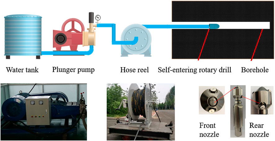
The self-propelled and rotary drill borehole and restoration device mainly consists of plunger pump, hose reel and self-propelled and rotary drill bit, as shown in Figure 1. The self-propelled and rotary drill bit is the key device for system movement and coal breaking power output. The high-pressure water jet is ejected from the rear nozzle of the drill bit to provide the forward power of the system, and from the front nozzle to provide the coal-breaking power; the broken coal slag is discharged out of the borehole with the backwater (Ma et al., 2014; Li et al., 2015; Chi et al., 2016). The rear nozzle is at certain eccentric angle along the circumference of the drill bit, which provides driving force to the drill while applying torque to achieve rotary jet propulsion. The resistance of the system is mainly composed of frictional force, gravity parting force and counter-thrust of the front nozzle.
2.2 Drill self-propelled force
The self-propelled force is the combined axial force between the drill bit and the high-pressure hose during the travel in the borehole, expressed as:
Where
When the jet formed by the front nozzle impacts the broken coal, it exerts reaction force on the drill bit, and according to Liu et al. (2006), the recoil force
Where
From this theory it follows that Equation 2 can also be used to calculate the thrust F1 formed by the rear nozzle.
For the frictional resistance f, the mass of the system gradually increases with the increasing distance of the system advance, so that the system frictional resistance f gradually increases. In order to ensure that the system travels stably in the borehole, the calculation of the self-propelled force should consider the change of the system mass due to the increase of the length of the restoration hole. In addition, the frictional resistance is also related to the borehole parameters, backwater speed and flow rate, especially the effect of backwater on frictional resistance, which is difficult to calculate with the theoretical model with high engineering applicability.
2.3 Frictional resistance
The system resistance consists of the frictional resistance of the drill bit and the high-pressure hose and the resistance of the backwater. Established theories only consider the effect of the length of the high-pressure hose in the system on the resistance (Liu et al., 2016b), ignoring the effect of the angle of the hole and the backwater on the resistance. In both elevated and pitched boreholes, the resistance is the vector sum of the frictional resistance and the component forces of the system gravity. Besides, the return water resistance is also an important component of the system resistance. Under the same flow condition, the larger the borehole angle, the higher the velocity of backwater and the higher the resistance. Therefore, considering the angle of the borehole and the backwater resistance, the total frictional resistance on the axis of the borehole restoration system is expressed as:
Where
The effect of backwater on system resistance is manifested in two aspects. First: backwater exerts buoyancy on the high-pressure hose and drill bit during the movement, which reduces the pressure of the pipe and drill on the borehole and decreases the frictional force. The gravity of the system with the buoyancy of the backwater considered is expressed as:
Where
Second: the backwater to the high-pressure hose produces friction, Li et al. (Ma et al., 2012; Li et al., 2017) based on the theory of the attached layer derived the friction of the high-pressure hose when the fluid returns from the annulus between the high-pressure hose and the well wall to the high-pressure hose as:
So
Where
Order
Then
Where k is the integrated friction coefficient.
The integrated friction coefficient is related to the friction resistance coefficient
2.4 Equations of motion
During the borehole restoration process, the gravitational force and frictional resistance of the system changes as the length of the restoration continues to increase. The existing theoretical model of borehole restoration ignores the change of mass during the motion of the system, and cannot accurately calculate the thrust force required to drive the system. Considering the change of mass during the borehole restoration process, the equation of motion of the restoration system by Newton’s law of variable mass is:
Where
Substituting equation (11) into (12) yields:
Let
According to the initial conditions: when
When the system thrust is constant value, the system movement speed decreases gradually as the restoration length continues to increase, and the restoration length reaches its maximum value when the drill speed is 0. The relationship between thrust force and restoration length is as follows:
Substitute Equation 2 into (16) to obtain the relationship between restoration length and nozzle parameters, system pressure, borehole parameters and pipe parameters as:
Where
From Equation 17, all parameters are known or measurable parameters except for the integrated friction coefficient k. Whether the integrated friction coefficient k is accurate determines the accuracy of this restoration model. Since there is no accurate value of the integrated friction coefficient k that can be drawn from the self-propelled and rotary drill borehole restoration technology, this paper uses experimental means to test and analyze it.
3 Integrated friction coefficient experimental study
3.1 Experimental conditions
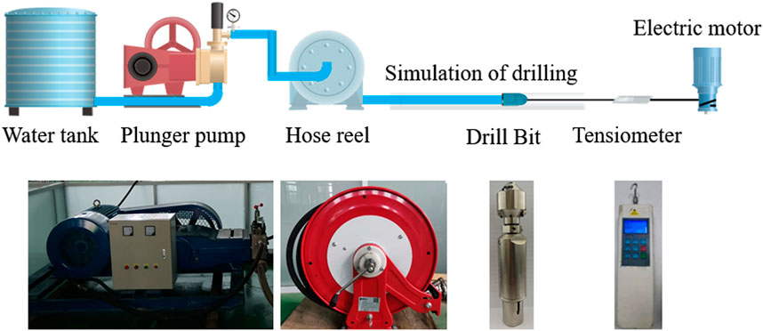
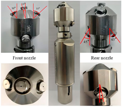
The experimental setup mainly consists of piston pump, hose reel, simulated borehole, self-propelled and rotary drill bit, digital display push-pull meter, intelligent pressure and flow meter and an electric motor, as shown in Figure 2. The rated pressure of the plunger pump is 35 MPa, and the rated displacement is 100 L/min. The experimental self-propelled and rotary drill bit is shown in Figure 3, with nozzle flow coefficient of 0.8, three 1 mm nozzles in the front nozzle, and 35°, 30° and 10° angles between the front nozzle and the center axis of the drill, and two 1.5 mm nozzles in the rear nozzle, with a 45° angle between the center axis of the drill bit and the eccentricity angle of 10°.
3.2 Experimental methods
The screen tube used for the experiments was consistent with the parameters of the screen tube commonly used in coal mine screen tube protection techniques. To carry out the resistance test experiments, the screen tube used for gas extraction is fixed to the ground and a self-propelled rotary drill bit connected to a hose reel is placed inside the screen tube. The drill is connected to a tensiometer by means of a wire and the other end of the tensiometer is connected to an electric motor. When testing the system resistance the wire is kept horizontal, the drill and high pressure hose are made to move at a constant speed through the screen tube by the pull of the motor.
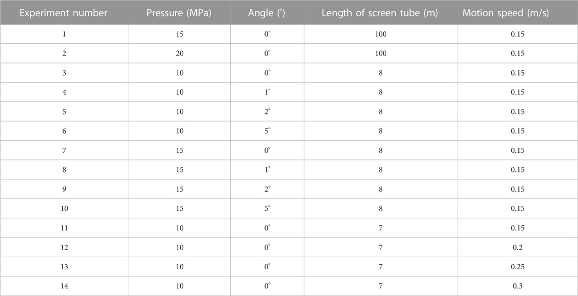
The system pressure, drilling angle, length of the screen tube and movement speed are changed in turn, other conditions remain unchanged, the system resistance test experiment is carried out, the experimental scheme is shown in Table 1. According to the experimental results, the influence of the length of the repair, the water return and the angle of the borehole on the resistance of the system is analysed.
When measuring the flow rate of return water in the screen tube, the angle of the screen tube was changed (0°, 1°, 2°, 5°) and the flow rate in the screen tube was measured every 0.5 m by an intelligent pressure flow meter to derive the law of change of water velocity in the screen tube.
4 Results and discussion
4.1 Experimental results and analysis
4.1.1 Effect of borehole restoration length on resistance
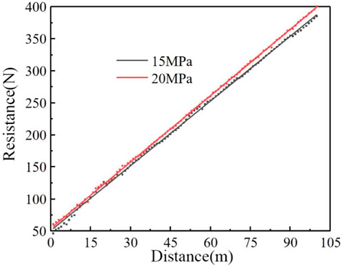
The resistance during the system movement is related to the length of the high-pressure hose, and the resistance increases gradually with the increase of the restoration length, as shown in Figure 4. The experimental pressure is 15 MPa and 20 MPa, the simulated borehole length is 100 m, and the diameter is 75 mm when the pressure increases from 15 MPa to 20 MPa, the front nozzle recoil force increases and the system resistance increases. With the pressure of 20 MPa, for example, the resistance is 60.77N at distance of 1 m, 158.45N at distance of 30 m, 260N at distance of 60 m, and 400.6N at distance of 100 m. With the increase of the restoration distance, the recoil force generated by the front nozzle of the drill remains unchanged, and the increase of the system resistance is obtained by the increase of the length of the high-pressure hose, so friction also increases. It can be seen from Figure 4 that the system resistance increases approximately linearly with the increase of the borehole restoration distance under the same pressure condition. Therefore, the system resistance can be expressed as kx, k is the integrated friction coefficient and x is the restoration length.
4.1.2 The effect of return water on resistance
The jet will be rapidly converted into return flow after impacting the wall of the borehole. Under the condition that the diameter of the borehole remains unchanged, when the pressure at the drill increases, the flow rate increases and the flow velocity of the backwater increases. Figure 5 shows the velocity distribution of backwater in the borehole, from the figure, we can see that the angle is 0°, the pressure is 10 MPa, the flow rate is 1.0 m/s at 0.5 m from the drill, when the distance continues to increase, the flow rate gradually decreases, and the flow rate at the exit of the simulated borehole is 0.2 m/s. Nearer to the drill is affected by the jet, the flow rate of backwater is faster, while at certain distance from the drill, the influence of the jet decreases. At certain distance from the drill, the influence of the jet decreases, and the flow rate of the backwater decreases and gradually stabilizes. When the angle of the borehole is 0°, the system pressure increases from 10 MPa to 15 MPa, and the flow rate of backwater at the exit of the simulated borehole increases from 0.2 m/s to 0.23 m/s, which makes the resistance of backwater to the front end of the drill bit and the high-pressure hose become larger, which is not conducive to the advance of the drill in the borehole. At the same pressure (e.g., 10 MPa), the angle of the borehole increases from 0° to 5°, and the backwater flow rate at the exit increases from 0.2 m/s to 0.54 m/s. The increase in angle increases the return water flow rate and leads to an increase in the integrated friction coefficient k.
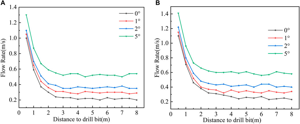
FIGURE 5. Return flow rate variation pattern (A) Flow rate variation pattern at different angles at 10 MPa (B) Flow rate variation pattern at different angles at 15 MPa.
With the backwater, the buoyancy of the water and the backwater resistance to the total frictional resistance is particularly important. The high-pressure hose is subjected to upward buoyancy as it moves through the water, and the reduction in positive pressure leads to reduction in friction. Backwater creates resistance to the drill bit and the high-pressure hose. Therefore, through experimental measurement, it is found that the integrated friction coefficient k is greater than μλ′g under the condition of backwater. Integrated friction coefficient k is 3.39 when the pressure is 10 MPa without backwater and 2.47 when there is backwater; integrated friction coefficient k is 3.7 when the pressure is 15 MPa without backwater and 2.72 when there is backwater. Taking the pressure of 10 MPa as an example, the integrated friction coefficient k is 3.7 when there is backwater.
4.1.3 Effect of the angle of the borehole on resistance
It can be seen from Figure 6 that the distance is long when the return flow is stable, so the flow rate at the outlet is used to calculate the resistance, the system movement speed is 0.15m/s, the relative speed of the return water is 0.35m/s, the viscous shear stress of the return water on the high-pressure hose wall is 5.37Pa, and according to formula (9), the return resistance per unit length is 0.39N. As shown in Figure 7, the simulated borehole diameter of 75 mm shows an increasing trend of system resistance with increasing angle of the borehole during the borehole restoration process. For example, when the pressure is 10 MPa, the simulated angle of the borehole is 0°, 1°, 2° and 5°, and the fitted integrated friction coefficient k is 2.47, 2.68, 2.93 and 3.65 respectively. The increase of angle of the borehole leads to the increase of system resistance mainly for two reasons: ① The high-pressure hose on the inner wall of the inclined borehole is subject to the vertical downward gravity and the support force perpendicular to the inner wall of the borehole. Gravity can be decomposed into the force perpendicular to the inner wall of the borehole downward and the force along the inner wall downward; where the two opposite forces perpendicular to the inner wall of the borehole is the balance force, the high-pressure hose by the force of gravity along the slope downward force becomes the resistance. When the angle of the borehole increases, the force of gravity increases. ②The water jet will produce backwater after impacting the borehole wall, and the backwater will produce resistance to the drill bit and the high-pressure hose. When the angle of the borehole increases, the return flow rate increases, and then the system resistance increases.
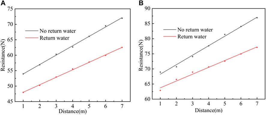
FIGURE 6. The effect of return water on resistance (A) The effect of return water on resistance at 10 MPa (B) The effect of return water on resistance at 15 MPa.
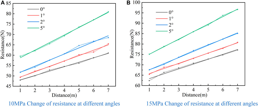
FIGURE 7. Law of change of resistance at different angles (A) 10 MPa Change of resistance at different angles (B) 15 MPa Change of resistance at different angles.
4.1.4 The effect of motion speed on resistance
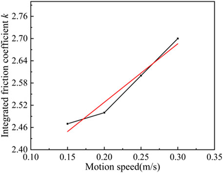
The screen tube was fixed horizontally on the ground, and the system resistance was measured at different motion speeds by changing the lifting speed of the motor, and the experimental results are shown in Figure 8. Under different speed conditions, the integrated friction coefficient k increases approximately linearly with the increase of speed, and the integrated friction coefficient k is 2.47, 2.5, 2.6 and 2.7 when the motion speed is 0.15 m/s, 0.2 m/s, 0.25 m/s and 0.3 m/s, respectively. In the process of borehole restoration, water is ejected from the nozzle and returned to the orifice along between the high-pressure hose and the borehole. Due to the viscosity of water, during the return process, the fluid mass immediately adjacent to the wall of the high-pressure hose adheres to the high-pressure hose, and there is no relative movement with the high-pressure hose. As the distance away from the high-pressure hose increases, the fluid velocity from the wall at zero rapidly increases to the speed of backwater. In the high-pressure hose near the wall area there is a large velocity gradient of flow, resulting in fluid to the boundary of the tangential stress, will produce resistance to the movement of high-pressure hose. The larger the velocity gradient, the greater the resistance. When the high-pressure hose movement speed increases, the relative speed of the backwater increases, the viscous shear stress increases, resulting in an increase in the integrated friction coefficient k.
4.2 Integrated friction coefficient correction
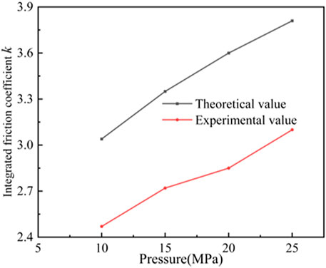
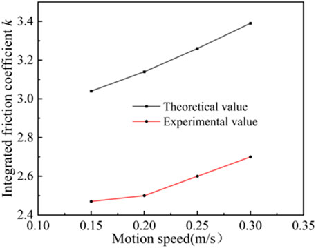
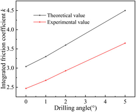
The integrated friction coefficient k is related to the friction coefficient, high pressure hose mass, angle of the borehole and backwater, which is key parameter of the restoration model. The system resistance test experiments were carried out by changing the system pressure, movement speed and angle of the borehole respectively, and the experimental results are shown in Figure 9, Figure 10 and Figure 11. The theoretical value of integrated friction coefficient k is larger than the experimental value. When the system pressure is 10 MPa, 15 MPa, 20 MPa and 25 MPa, the theoretical values of integrated friction coefficient are 3.04, 3.35, 3.6 and 3.81 respectively, and the experimental values are 2.47, 2.72, 2.85 and 3.1 respectively; when the motion speed is 0.15 m/s, 0.2 m/s, 0.25 m/s and 0.3 m/s, the integrated friction coefficient The theoretical values are 3.04, 3.14, 3.26, 3.39, and the experimental values are 2.47, 2.5, 2.6, 2.7, respectively; the theoretical values are 3.04, 3.3, 3.6, 4.5, and the experimental values are 2.47, 2.68, 2.93, 3.65, respectively, when the angle of the borehole is 0°, 1°, 2°, 5°, and the theoretical values are 3.04, 3.3, 3.6, 4.5, respectively. The friction coefficient between the hose and the orifice wall is assumed to be constant, and the orifice flow rate is used instead of the backwater flow rate, and the theoretical integrated friction coefficient k values will produce errors. Therefore, after the integrated friction coefficient k is calculated by Equation 9 and (10), it needs to be corrected. According to the experimental results of system resistance tests under different conditions, the correction factor of the integrated friction coefficient k is 0.8.
4.3 Experimental validation and analysis of the restoration model
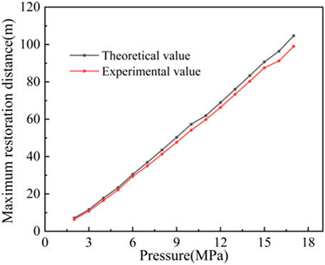
The maximum restoration distance, as an important parameter of the self-propelled and rotary borehole restoration technology, can be calculated theoretically and directly affects the field application of the self-propelled and rotary borehole restoration technology. Therefore, it is necessary to verify the accuracy of the equations of motion of the self-propelled and rotary drill for borehole restoration. The parameters of the self-propelled and rotary drill bit used for the borehole restoration experiments were set as follows: 2 rear nozzles, 1.5 mm diameter, 45° angle to the center axis of the drill, and 10° eccentricity angle. According to the theoretical analysis and experimental results, the integrated friction coefficient k was selected, and the theoretical calculation model of the maximum restoration distance was experimentally verified under different pressure conditions respectively, and the comparison graph between the theoretical calculation and experimental values of the maximum restoration distance was obtained, as shown in Figure 12. From Figure 12, it can be seen that: the theoretical calculated value of the maximum restoration distance of the self-propelled and rotary drill and the experimental value vary with the system pressure in a more consistent manner. However, the theoretical value is slightly larger than the experimental value, and the error value increases gradually with the increase of the restoration distance, and the error is 5.7 m at the restoration distance of 104.7 m.
As can be seen from Figure 12, the error of the theoretical calculated value increases with the increase of the restoration borehole length. The increase in error mainly includes three reasons: ① The backwater has typical turbulence characteristics during the borehole restoration process. In the theoretical model, the time-averaged velocity is used to characterize the backwater velocity for the convenience of calculation. The turbulence of backwater becomes more and more significant with the increase of jet pressure, and the error value generated by using the hourly average velocity becomes larger and larger. Therefore, as the length of the restoration borehole increases, the required jet pressure increases, resulting in an increase in the error of the theoretical calculation. ②In calculating the integrated friction coefficient k, the friction coefficient between the high-pressure hose and the borehole wall was assumed to be constant. However, in the experimental process, the simulated borehole conditions are not the same everywhere, and with the increase of the restoration distance, the contact between the high-pressure hose and the borehole wall is not exactly the same, resulting in changes in the friction coefficient between the high-pressure hose and the borehole wall. ③ The system movement speed increases, the relative speed of backwater increases, and the viscous shear stress increases accordingly. As a result, the integrated friction coefficient k changes during the borehole restoration process. However, for the convenience of calculation in the theoretical model, the integrated friction coefficient k is selected according to the experimental results of resistance test and the theoretical value, which will produce a certain error, resulting in the experimental value of the restoration length being smaller than the theoretical value.
The maximum restoration distance of the self-propelled borehole restoration simulation experiment is in good agreement with the theoretical value, and the restoration model can meet the engineering requirements of long-distance borehole restoration.
5 Conclusion
1) Based on Newton’s law of variable mass, the equation of motion for self-propelled borehole restoration is established, which takes into account the effects of parameters such as borehole length, angle of the borehole, backwater and restoration speed on the integrated friction coefficient k. The relationship between restoration length and hydraulic parameters, borehole parameters and pipe parameters are derived, and it is clear that the integrated friction coefficient k is the key parameter of the equation of motion.
2) The system resistance test experiment was carried out, and the influence law of factors such as borehole length, angle of the borehole, backwater and restoration speed on the integrated friction coefficient k was obtained: the system resistance increased linearly with the increase of borehole restoration length; the backwater produced resistance to the drill bit and high-pressure hose, and the increase of angle of the borehole and jet pressure could both lead to the increase of backwater flow rate, which made the backwater resistance increase; The increase of motion speed leads to the increase of viscous shear stress of backwater on the wall of high-pressure hose, which causes the increase of integrated friction coefficient k. Based on the results of the experimental test analysis, the theoretical value of the integrated friction coefficient k is corrected, and the correction factor is 0.8.
3) The maximum borehole restoration length under different hydraulic parameters and borehole parameters is analyzed and the equation of motion is verified through the simulation experiment of self-driven borehole restoration. The results show that the equation of motion can calculate the borehole restoration length more accurately and can provide theoretical support for the engineering application of through-hole and down-hole restoration.
Data availability statement
The raw data supporting the conclusions of this article will be made available by the authors, without undue reservation.
Author contributions
MW: experimental method design, manuscript writing. Data analysis. PG: chart drawing, experimental optimization, gas data collection. WD: manuscript revise. FY: physical testing, model parameter optimization, capital planning.
Conflict of interest
MW is employed by the Company Xinyi Mine Industry Co., Ltd., Yima Coal Industry Group Co., Ltd.
The remaining authors declare that the research was conducted in the absence of any commercial or financial relationships that could be construed as a potential conflict of interest.
Publisher’s note
All claims expressed in this article are solely those of the authors and do not necessarily represent those of their affiliated organizations, or those of the publisher, the editors and the reviewers. Any product that may be evaluated in this article, or claim that may be made by its manufacturer, is not guaranteed or endorsed by the publisher.
References
Chi, H., Li, G., Liao, H., Tian, S., and Song, X. (2016). Effects of parameters of self-propelled multi-orifice nozzle on drilling capability of water jet drilling technology. Int. J. Rock Mech. Min. Sci. 86, 23–28. doi:10.1016/j.ijrmms.2016.03.017
Fan, J., Jiang, D., Liu, W., Wu, F., Chen, J., and Daemen, J. J. K. (2019). Discontinuous fatigue of salt rock with low-stress intervals. Int. J. Rock Mech. Min. Sci. 115, 77–86. doi:10.1016/j.ijrmms.2019.01.013
Fan, J., Liu, P., Li, J., and Jiang, D. (2020a). A coupled methane/air flow model for coal gas drainage: Model development and finite-difference solution. Process Saf. Environ. Prot. 141, 288–304. doi:10.1016/j.psep.2020.05.015
Fan, J., Liu, W., Jiang, D., Chen, J., William, T. N., and Daemen Jaak, J. K. (2020b). Time interval effect in triaxial discontinuous cyclic compression tests and simulations for the residual stress in rock salt. Rock Mech. Rock Eng. 53, 4061–4076. doi:10.1007/s00603-020-02150-y
Fan, J., Xie, H., Chen, J., Jiang, D., Li, C., William, T. N., et al. (2020c). Preliminary feasibility analysis of a hybrid pumped-hydro energy storage system using abandoned coal mine goafs. Appl. Energy 258–114007. doi:10.1016/j.apenergy.2019.114007
Force, J. (2011). Underground resistance: Focus on 'fracking' for shale gas extraction. Mag. Int. Water Assoc. 2, 46–48.
Guo, Y., Wei, G., and Li, X. (2019). Key technology study of regional gas control in kilometre-directional coal borehole in Zhaogu No.2 mine. J. Henan Polytech. Univ. Sci. 38, 14–19.
He, Y., Jiang, D., Chen, J., Liu, R., Fan, J., and Jiang, X. (2019). Non-monotonic relaxation and memory effect of rock saltffect of rock salt. Rock Mech. Rock Eng. 52, 2471–2479. doi:10.1007/s00603-018-1718-4
Kang, Y., Fan, J., Jiang, D., and Li, Z. (2021). Influence of geological and environmental factors on the reconsolidation behavior of fine granular salt. Nat. Resour. Res. 30, 805–826. doi:10.1007/s11053-020-09732-1
Li, F., and Dong, C. (2022). Key technology of directional long borehole gas drainage in protective layer mining. Coal Technol. 41, 160–163.
Li, G., Huang, Z., and Li, J. (2017). Study of the key techniques in radial jet borehole. Pet. Boreh. Tech-niques 45, 1–9.
Li, Q., Yao, K., Fang, J., Yao, Y., and Shi, C. (2023). Directional drilling technology and equipment for efficient and accurate gas drainage underground coal mine. Coal Sci. Technol. 1, 1–9.
Li, Z., Yang, Z., Fan, J., Marion, F., Jiang, D., and Daniel, N. (2022). Fatigue mechanical properties of salt rocks under high stress plateaus: The interaction between creep and fatigue. Rock Mech. Rock Eng. 55, 6627–6642. doi:10.1007/s00603-022-02983-9
Li, J., Li, G., Huang, Z., Song, X., Yang, R., and Peng, K. (2015). The self-propelled force model of a multi-orifice nozzle for radial jet drilling. J. Nat. Gas Sci. Eng. 24, 441–448. doi:10.1016/j.jngse.2015.04.009
Liu, C., Yang, M., and Su, J. (2019). Experimental study on mix proportion of magnetic sealing slurry for gas drainage borehole. China Saf. Sci. J. 29, 84–89.
Liu, R., Yi, H., Zhao, Y., Jiang, X., and Ren, S. (2020). Tunnel construction ventilation frequency-control based on radial basis function neural network. Automation Constr. 118, 103293. doi:10.1016/j.autcon.2020.103293
Liu, W., Zhang, X., Fan, J., Zuo, J., Zhang, Z., and Chen, J. (2020). Study on the mechanical properties of man-made salt rock samples with impurities. J. Nat. Gas Sci. Eng. 84, 103683. doi:10.1016/j.jngse.2020.103683
Liu, Y., He, A., and Wei, J. (2016a). Plugging factor and new plugging method to hydraulic relieving stress. J. China Coal Soc. 41, 1963–1967.
Liu, Y., Liang, B., and He, A. (2016b). Research on theory and technical parameter of borehole restoration for self-propelling and rotating drill. J. Saf. Sci. Technol. 12, 39–44.
Liu, Y., Quanbin, B. A., and Shen, K. (2020a). Research and application of water jet and cooperative restoration technology in gas drainage. Min. Saf. Environ. Prot. 47, 56–60.
Liu, Y., Li, Z., and Wei, J. (2020b). Erosion model of abrasive air jet used in coal breaking. J. China Coal Soc. 45, 1733–1742.
Liu, Y., Wei, J., and Wang, D. (2018). Erosive wear characteristic of rock impacted by abrasive gas jet. J. China Coal Soc. 43, 3033–3041.
Liu, Y., Lu, T., and Liu, X. (2006). Self-Feeding horizontal borehole technology with super-short radius for coal-bed me-thane wells. Nat. Gas. Ind. 26, 69–72.
Long, W., Zhao, L., and Chen, D. (2019). Experimental study on coal seam permeability enhancement by directional long borehole hydraulic fracturing along seam direction. J. Henan Polytech. Univ. Sci. 38, 10–15.
Ma, D., Li, G., and Huang, Z. (2014). Mechanism of a self-propelled multi-hole jet bit and influencing rules on its self-propelled force. Nat. Gas. Ind. 34, 99–104.
Ma, D., Li, G., Huang, Z., Niu, J., Hou, C., Liu, M., et al. (2012). A model of calculating the circulating pressure loss in coiled tubing ultra-short radius radial drilling. Petroleum Explor. Dev. Online 39, 528–533. doi:10.1016/s1876-3804(12)60072-x
Ma, Y., Wu, J., Feng, R., and Li, L. (2022). Pressure relief gas drainage by directional drilling hydraulic fracturing in hard roof. Min. Saf. Environ. Prot. 49, 52–56.
Qi, Q., Pan, Y., and Shu, L. (2018). Theory and technical framework of prevention and control with different sources in multi-scales for coal and rock dynamic disasters in deep mining of coal mines. J. China Coal Soc. 43, 1801–1810.
Shu, L., Qi, Q., and Wang, K. (2018). Coordinated prevention mechanism of pressure-relief and rock properties modification for coal and gas outburst in deep mining of coal mines. J. China Coal Soc. 43, 3023–3032.
Su, X., Song, J., and Guo, H. (2020). Increasing production mechanism and key technology of gas extraction in coal mines. Coal Sci. Technol. 48, 30.
Su, X., Xiao, L., and Ma, B. (2014). Restorationing and enhancing permeability technology and equipment of gas drainage bore-hole. Coal Sci. Technol. 42, 58–60.
Teng, J., Qiao, Y., and Song, P. (2016). Analysis of exploration, potential reserves and high efficient utilization of coal in China. Chin. J. Geophys. 59, 4633–4653.
Wang, C., Li, S., Zhang, Y., Guo, Y., Sun, S., Chen, D., et al. (2022). Enhanced gas drainage technology by staged fracturing in long bedding borehole in hard coal bed of underground coal mine and its application. Coal Geol. Explor. 50, 72–81.
Wu, Q., Tu, K., Zeng, Y., and Liu, S. (2019). Discussion on the main problems and countermeasures for building and upgrade version of main energy(coal) industry in China. J. China Coal Soc. 44, 1625–1636.
Xiao, L., Lin, H., and Zhang, S. (2014). Research on gas drainage borehole restoration mechanism and application. China coal 40, 102–105.
Xiong, W., Shen, K., and Liu, Y. (2020). Progress in research on borehole restoration and protect technology for gas drainage in coal mine. Min. Saf. Environ. Prot. 47, 106–110.
Xu, Y., Liang, X., and Sun, L. (2022). Application study on gas drainage technology of high-level directional drilling in Huozhou mining area. Coal Technol. 41, 148–150.
Yuan, L. (2016). Strategic thinking of simultaneous exploitation of coal and gas in deep mining. J. China Coal Soc. 41, 1–6.
Keywords: water jets, self-propelling, restoration distance, change of resistance, gas extraction, borehole restoration
Citation: Wang M, Guo P, Dong W and Yang F (2023) Research on borehole repair model and working parameters optimization of self-propelled rotary excavator. Front. Earth Sci. 11:1137946. doi: 10.3389/feart.2023.1137946
Received: 05 January 2023; Accepted: 23 February 2023;
Published: 14 March 2023.
Edited by:
Alexandre Chemenda, UMR7329 Géoazur (Geoazur), FranceReviewed by:
Yunfeng Zhao, Yangtze University, ChinaZongze Li, UMR5259 Laboratoire de Mecanique des Contacts et des Structures, France
Copyright © 2023 Wang, Guo, Dong and Yang. This is an open-access article distributed under the terms of the Creative Commons Attribution License (CC BY). The use, distribution or reproduction in other forums is permitted, provided the original author(s) and the copyright owner(s) are credited and that the original publication in this journal is cited, in accordance with accepted academic practice. No use, distribution or reproduction is permitted which does not comply with these terms.
*Correspondence: Pengyu Guo, MTQxMjg0NTI5NEBxcS5jb20=; Wenxin Dong, ZG9uZ3dlbnhpbkBjcXUuZWR1LmNu
 Mian Wang1,2,3
 Pengyu Guo
 Fan Yang