 Jun Wang1
 Xun Li
 Shengzhi Wu
- 1School of Civil Engineering, Shandong Jianzhu University, Jinan, China
- 2China Railway 14th Bureau Group Co., Ltd., Jinan, China
The pipe roof is an effective means to control the surface settlement during the construction of the super-shallow buried subway station. The transverse pipe roof method can not only reduce the construction work surface, but also improve the construction efficiency by multi-stage flow construction. Based on the transfer station project of the Olympic Sports Center of Jinan Rail Transit Line 3, the ground settlement law caused by the excavation of ultra-shallow buried subway station under the action of transverse pipe roof is analyzed through field measurement. The mechanism of pipe roof controlling ground settlement and the influence of steel pipe spacing and steel pipe length on the bearing mechanism of pipe roof are analyzed by numerical simulation. The following conclusions are drawn. 1) The surface settlement curve caused by the excavation of the small pilot tunnel in the lateral direction of the station is a wavy U-shaped, and the surface settlement curve becomes a smooth U-shaped after the soil is broken. In the longitudinal direction of the station, the surface settlement is jagged, and the surface settlement above the pipe roof is less than the surface settlement between the pipe roofs. 2) After soil excavation, pipe roof can bear the load of surrounding rock and restrain the settlement of soil above, and soil arch effect is formed between pipes to restrain the relaxation of soil between pipes. With the increase of the spacing of the steel pipe, the height of the soil arch increases. After exceeding a certain spacing, the micro-soil arching effect disappears and the surface settlement increases. 3) The length and stiffness of pipe roof will affect the bearing capacity of pipe roof and there is an upper limit. When it exceeds the upper limit, increasing the length or stiffness of pipe roof has little effect on the control effect of ground settlement. The research can provide reference for shallow buried excavation station and other projects.
1 Introduction
As urban rail transit is developed, subway stations will inevitably pass through densely populated city centers with large traffic flow. The construction of these stations should not affect the normal use of existing buildings. The pipe roof method involves pre-jacking steel pipes in the upper peripheral soil layer of a structure and forming an advanced support system that can resist upper loads by setting a connection between the steel pipes or changing the structure between adjacent steel pipes (Wang et al., 2020; Cai et al., 2022; Zhang et al., 2022). Because this method can realize micro-disturbance crossing of an environment under the condition of ultra-shallow overburden soil, and the construction area is relatively small, it is very suitable for the construction of underground structures in current densely populated urban spaces (Wang et al., 2018; Lu et al., 2022), such as the shield section project of the Beijing Metro Line eight under the existing Line 10 (Tao et al., 2018), the ultra-shallow buried Ping anli subway station project of Line 10 (Gao, 2018), and the construction project of Taiyuan Yingze Street under the Taiyuan Railway Station (Jia et al., 2021).
Many scholars have carried out a considerable amount of research on the mechanical behavior of pipe roof excavation. Xie et al. (2019a); Xie et al. (2019b) studied the excavation mechanical properties of a pipe roof under a rectangular cross-section by the limit analysis method and found that the pipe roof plays an important role in reducing ground settlement and earth pressure. Wu et al. (2018) found that the pipe roof can effectively reduce the settlement of the surface vault and the grouting can limit the development of a plastic zone by numerical simulation of the combined effect of pipe roof and rock grouting reinforcement. Considering the interaction between pipes, Yang et al. (2019) established a two-parameter elastic foundation beam theoretical model based on the soil arching effect between pipes and used this model to calculate the deflection and internal force of the pipe roof. Through laboratory experiments and numerical simulation, Deng et al. (2021) proposed a method considering the interaction between pipes and soil to analyze the frictional resistance during pipe jacking. Li et al. (2022) established a mechanical model of the pipe roof considering the soil arching effect and the time-space effect of stress release. Based on the Pasternak elastic-plastic foundation beam theory, the internal force and deflection solutions of the pipe roof were derived. Considering the influence of a three-dimensional arching effect, Ji et al. (2018) used the improved Protodyakonov arch model to calculate the vertical earth pressure above the pipe roof and quantified the contribution of soil cohesion to reduce the vertical earth pressure. Shi et al. (2021) found that the stress state of the pipe roof is divided into three parts with the excavation process by numerical simulation and field monitoring. Heng et al. (2022) proposed a calculation model based on deformation control based on the change in the pipe roof construction process and found that the deformation of the pipe roof at the entrance and middle span was large. In terms of the influencing factors of the pipe roof, through numerical simulations, An et al. (2021) found that increasing the pipe diameter, reducing the aspect ratio, and reducing the excavation height can improve the stability of the tunnel surface. Zarei et al. (2019) analyzed the process of tunnel excavation under the action of a pipe roof by numerical simulation and found that increasing the parameters of pipe roof can reduce the surface settlement and internal force of the pipe roof.
A transverse pipe roof can form a transverse bearing system with large stiffness in a pilot tunnel. The construction joints are simple, and the force transmission is clear (Guo, 2019; Zhang et al., 2021). Presently, research has mainly focused on the bearing mechanism in the construction process of longitudinal pipe roofs, and research on transverse pipe roofs is limited. Compared with the longitudinal pipe roof, the transverse pipe roof can be achieved through segmented flow construction, improving the construction efficiency. Furthermore, as the steel pipe is short, its construction is easy to perform, and it is easy to meet control requirements. Two kinds of pipe roof arrangements are shown in Figure 1. Based on the transfer station process of the Olympic Sports Center Line of Line R3 of the Jinan Rail Transit, through field monitoring and numerical simulation, this paper studies the mechanism of surface settlement control by a transverse pipe roof and the influence of pipe spacing and length on its bearing mechanism. The findings of this study can serve as a reference for other underground projects under the action of transverse pipe roof.
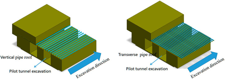
FIGURE 1. Pipe curtain arrangement form.
2 Engineering scenarios
The transfer station project of the West Station of the Olympic Sports Center along the Jinan Rail Transit R3 Line is located at the intersection of Jingshi Road and Olympic Sports West Road in Jinan City. It is arranged in a one-word shape along the east-west direction of Jingshi Road. The northwest quadrant of the station is Sinopec Gas Station, the north side is near the Golden Age Square, and the south side is the Olympic Sports Center. The surrounding traffic volume is considerable, and the pipelines are large. The proposed station is an underground two-story double-column island platform station, with a total outsourcing length of 273 m and a total outsourcing width of 24.1 m for the standard section. The transfer node with the R2 line has been implemented for 31.15 m. The overburden of the station roof is 3.8–4.4 m, and the depth of the foundation pit is about 18.5 m. Figure 2 shows the geographical environment and surrounding buildings of the project.
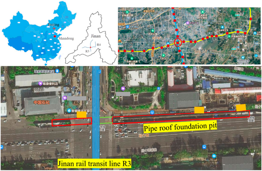
FIGURE 2. Geographical location of the station.
According to the geomorphological characteristics, the site geomorphic units are mainly hills and residual hills. The terrain, which is undulating, changes greatly. The ground elevation is 87.25–132.39 m. The soil in this area belongs to the quaternary stratum, which is composed of artificial fill, silty clay, gravel, and gravel-containing silty clay. The surrounding soil of the roof of the station in the underground excavation section is mainly plain fill and silty clay. The stratum distribution in the construction area of the station is shown in Figure 3, and the physical and mechanical parameters of the soil layer are shown in Table 1.
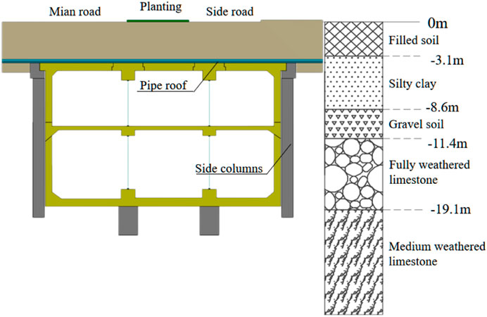
FIGURE 3. Longitudinal profile of the stratum of the station.
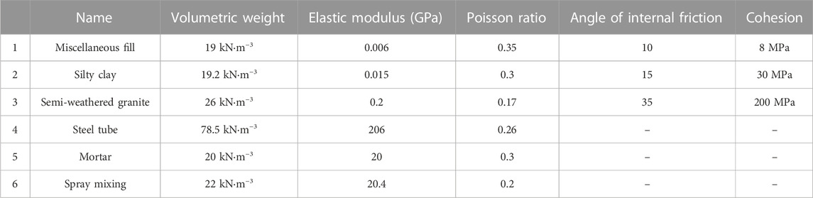
TABLE 1. Building materials and station support parameters.
3 Transverse pipe roof method and construction monitoring of subway station
3.1 Construction of subway station by transverse pipe roof method transverseabrication of specimens
Pipe roof excavation is adopted for the transfer station of the Jinan Olympic Sports Center West Station. Using this method, transverse channels can be established in three shafts respectively. Each transverse channel can meet the excavation requirements, so as to realize the flow construction of multiple construction sections and improve the construction efficiency. At the same time, compared with large section excavation, small pilot tunnel excavation method is more convenient. First, the pipe roof foundation pit is set up in the green belt area of the main road and auxiliary road of Jingshi Road. Pipe jacking construction is carried out on the north and south sides through the pipe roof foundation pit. After jacking and docking of the entire pipe roof, the pipe roof foundation pit is backfilled. Four-pilot tunnel excavation is adopted for the station. First, the transverse channel is excavated from three construction shafts to the other side at the same time, and then the longitudinal excavation is carried out by means of a small pilot tunnel. Pilot tunnels 2# and 4# are excavated before pilot tunnels 1# and 3#. After the excavation of the pilot tunnel is completed, the independent foundation, bottom longitudinal beam, side pile, middle column, crown beam and top longitudinal beam are constructed in the pilot tunnel, then the arch is excavated and constructed, and finally the soil is excavated layer by layer and the internal structure of the station is constructed. The construction process of the pipe roof and the main body of the station is shown in Figure 4.
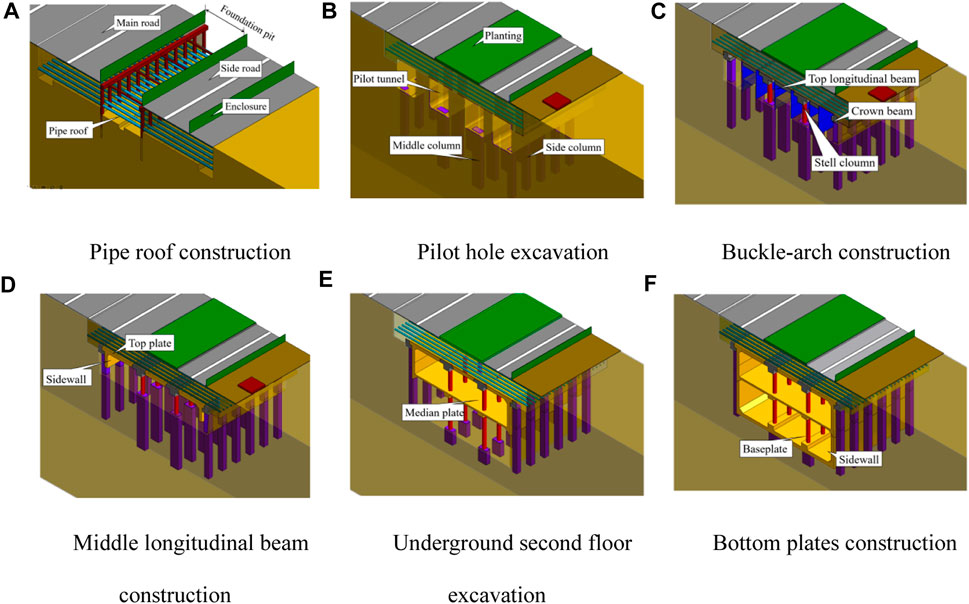
FIGURE 4. Sequence diagram of station construction.
The construction method of the pipe roof is that the pipe roof is excavated at the same time, and the Φ406 × 18 mm steel pipe is jacked into the section. The length of the single section is 3.0–3.5 m, and the pipe joint is welded by carbon dioxide protection welding. Finally, M20 cement mortar is used to fill the steel pipe. A large sample of the tube roof is shown in Figure 5.
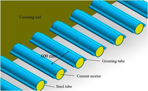
FIGURE 5. Large sample of pipe roof.
3.2 Field monitoring of super shallow excavation station
In order to reduce the influence of the transverse passage on field monitoring, the DBC58 section, which is about 20 m away from the transverse passage, is taken as the research object. The measuring points from north to south are T-1–T-10, among which the measuring points T-3, T-5, T-7, and T-9 are within the span of the small pilot tunnel. A certain area above the 3# pilot tunnel is taken as the research object in the longitudinal direction of the station. The measuring points from north to south are L-1–L-10. Figure 6 is the arrangement of measuring points and field monitoring diagram.
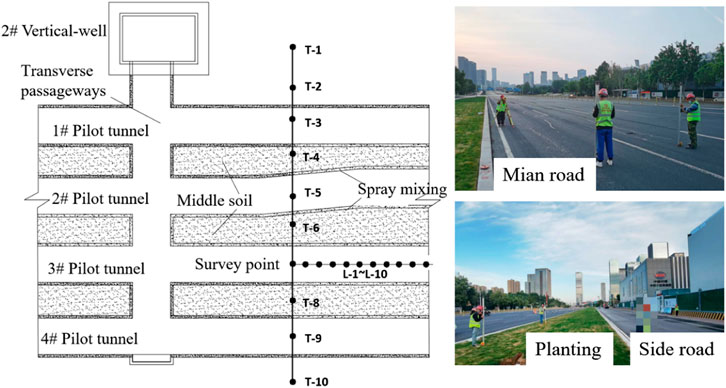
FIGURE 6. Measuring point layout.
Figure 7 shows the on-site surface monitoring results. The cross-sectional monitoring data of the station shows that the surface settlement increases considerably during excavation of the pilot tunnel, and the excavation of the platform layer has a relatively small impact on the surface settlement. In addition, the surface settlement curve during excavation of the pilot tunnel shows a wavy shape, and the soil settlement at the excavation site is significantly higher than that of the surrounding soil. The surrounding soil plays a supporting role in the pipe roof structure; after the middle soil is broken, the wave in the surface subsidence curve disappears. According to an analysis of the longitudinal monitoring data of the station, the surface settlement curve exhibits a jagged change. After excavation of the 1# and 3# pilot tunnels, the settlement value of some points is significantly higher than that of their adjacent points. After excavation of the platform layer, the surface settlement curve exhibits a wavy shape. In addition, the surface settlement during the excavation of the pilot tunnel accounts for a large proportion, and the excavation of the platform layer has little effect.
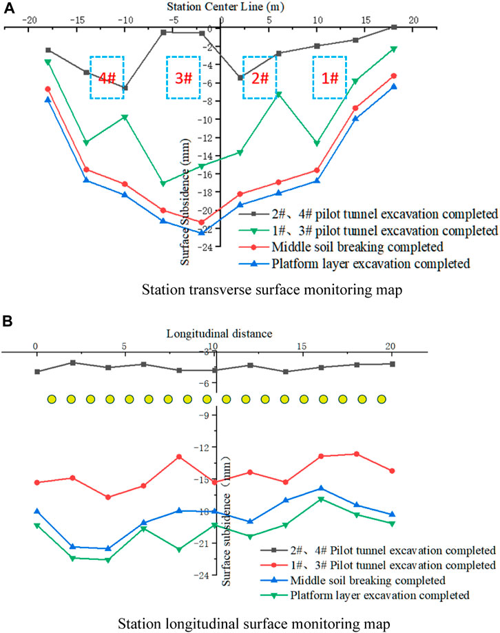
FIGURE 7. Measured field data.
4 Numerical simulation of super shallow excavation station construction
4.1 Calculation model establishment
The finite element analysis software is used to simulate the construction stage of the main body of the station under the bearing of the pipe roof. According to the actual construction influence range of the project, a three-dimensional model is established as shown in Figure 8. The size of the calculation model is 100 (transverse) × 20 (longitudinal) × 40 m (depth). The Drucker–Prager constitutive model is adopted for the soil. The solid element and elastic constitutive model are adopted for the steel pipe group and mortar in the pipe roof structure, respectively. The spray mixing structure adopts 2D plane plate element. The bottom of the model boundary condition is a fixed end constraint, and the side boundary is a free hinged constraint in the Z direction. The building materials and tunnel support parameters are shown in Table 1.
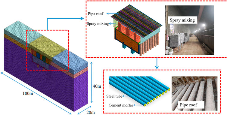
FIGURE 8. Three-dimensional finite element model.
4.2 Analysis of ground settlement
The surface settlement cloud map of each stage during the construction of the station under the advanced support of the pipe roof is shown in Figure 9. Figure 10 is the surface settlement curve of each stage. The numerical simulation results exhibited that, after the excavation of the lower soil, the corresponding surface has a significant settlement. After the excavation of pilot tunnels 2# and 4# and before the excavation of pilot tunnels 1# and 3#, the surface settlement is concentrated above pilot tunnels 2# and 4#, and the settlement in other areas is lower; after the excavation of pilot tunnels 1# and 3# is completed, the settlement of the soil above tunnels increases significantly and aggravates the surface settlement in other areas. The settlement of the soil above pilot tunnels 2# and 3# is large, and the entire surface settlement curve assumes a wavy U-shape. The settlement of the soil above the unexcavated area is relatively small, which plays a supporting role in the pipe roof structure. After the soil layer (middle soil) between the pilot tunnels is broken, the settlement curve changes from a wavy U-shape to a relatively smooth U-shape, and the maximum surface settlement occurs in the middle of the station. After the excavation of the platform layer, the surface settlement trend is consistent with the trend after the middle soil is broken.
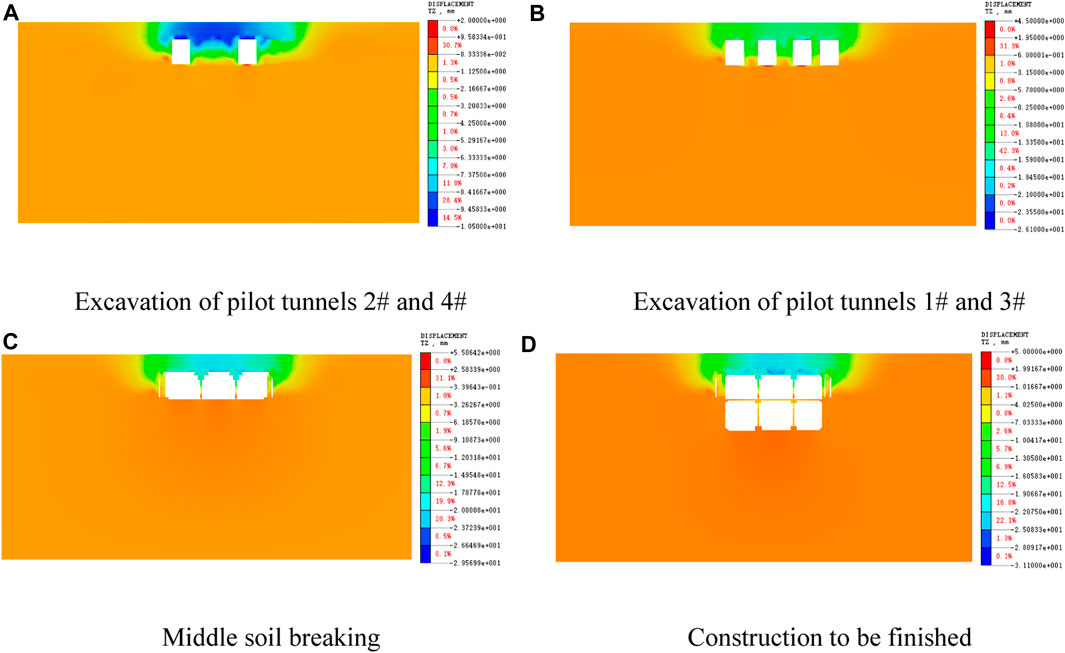
FIGURE 9. Surface subsidence cloud map.
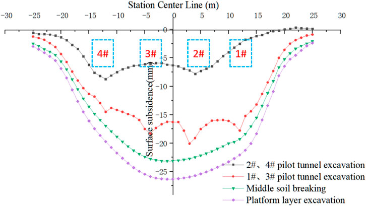
FIGURE 10. Surface subsidence curve of the entire construction process.
Previous studies have revealed that excavation of pilot tunnels and removal of supporting structures are the key to surface subsidence control (Guo et al., 2021; Song et al., 2022). After the excavation of pilot tunnel 2# and 4#, the ground settlement above the excavation is large, with a maximum value of 8.3 mm; after excavation of pilot tunnels 1# and 3#, the surface settlement increases significantly, and the maximum settlement increases to 20.2 mm. Compared with the excavation process of pilot tunnels 2# and 4#, the maximum settlement increases by 140%, and the surface settlement range expands. The surface settlement has a U-shaped curve, with a large settlement in the middle and a small settlement at both ends. After the middle soil is broken, the maximum settlement increases to 24.9 mm, which is an increase of 4.7 mm, accounting for about 45% of the settlement value in the excavation stages of pilot tunnels 2# and 4#, and the maximum settlement position appears above pilot tunnels 2# and 3#. After the excavation of the platform layer, the maximum surface settlement is 26.5 mm, an increase of 1.6 mm.
In order to study the characteristics of surface subsidence in the longitudinal direction of the station, the surface subsidence curves above pilot tunnels 2# and 3#, and above the middle soil are extracted. The position of the survey line is shown in Figure 11. The survey line A is located above pilot tunnel 2#, the survey line B is located above pilot tunnel 3#, and the survey line C is located above the middle soil. The surface settlement curve is shown in Figure 12.
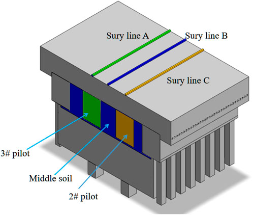
FIGURE 11. Line position diagram.

FIGURE 12. Longitudinal surface subsidence map of different parts.
Figure 12A shows that, when pilot tunnels 1# and 3# are not excavated, the surface settlement is approximately a smooth horizontal line, and the settlement of soil in each part is not much different. However, after the excavation of pilot tunnels 1# and 3#, the settlement of each part is different, and the surface settlement curve also exhibits a serrated shape owing to fluctuations. During soil breaking and platform excavation, although the surface settlement increases, the settlement curve remains jagged. The surface settlement of line B and line C is analyzed. The serrated settlement curve of line C appears for the first time during the excavation of pilot tunnels 2# and 4#. The serrated settlement curve of line B appears after the middle soil is broken. It can be seen that the serrated settlement curve first appears after excavation of the lower soil and continues until the end of the main construction of the station.
With the construction process of the main body of the station, the numerical simulation and field measurement results on the transverse section show a change from a jagged U-shape to a smooth U-shape, and the settlement of the pilot tunnel excavation stage accounts for a high proportion of the total settlement of the entire construction, and the influence of the platform layer on the surface settlement is relatively small. On the longitudinal section, both numerical simulations and field measurements reveal serrated surface settlement curves after excavation of the lower soil. It can be seen that the numerical simulation results are in good agreement with the field measured data, and the numerical simulation can reflect the actual bearing state of the pipe roof.
4.3 Analysis of pipe roof deformation
Figure 13 shows the deformation nephogram of a single steel pipe in the pipe roof during the entire construction process. It can be seen that the stress form of a single steel pipe is similar to that of a simply supported beam (Zhang et al., 2018; Liu et al., 2019; Xiao et al., 2019). Figure 14 shows the deflection curve of pipe roof, from which it can be seen that during the excavation of pilot tunnels 2# and 4#, the pipe roof above the excavation area sinks, and the sinking position appears above pilot tunnels 2# and 4#. The deflection value is about 5.2 mm. After the excavation of pilot tunnels 1# and 3# is completed, the pipe roof shows the overall subsidence, and the settlement of the middle and right ends of the pipe roof increases. The deflection values of the right end and middle are 14.1 and 11.8 mm, respectively. Furthermore, the settlement of the left end is 9.7 mm. After the middle soil is broken, the subsidence in the middle of the pipe roof increases, and the subsidence at both ends changes slightly. The deflection value in the middle of the steel pipe in the pipe roof structure is the largest, and its maximum value is 19.1 mm. The steel pipe exhibits the stress state of a simply supported beam with bearing displacement at both ends. During the excavation of the platform layer and the subsequent construction process, the settlement value of the pipe roof increases slightly, but the overall trend of the pipe roof is consistent with that after the soil was broken.
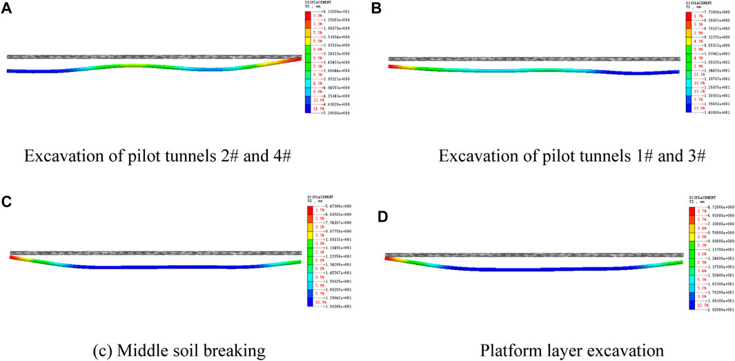
FIGURE 13. Steel tube deformation nephogram.
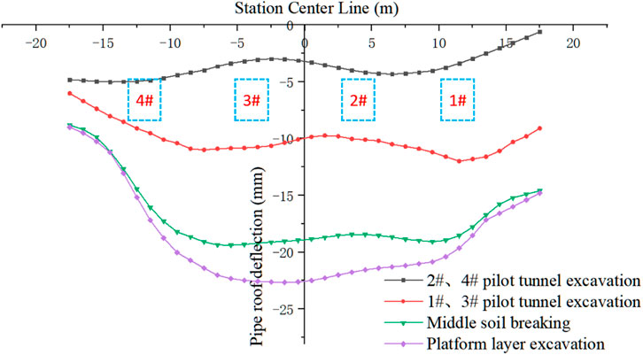
FIGURE 14. Steel tube deflection curve.
The above analysis shows that the deflection value of the pipe roof and the trend of surface settlement change with the excavation sequence during the excavation stage. The deflection value at the excavation site is relatively high. After the middle soil is broken, overall settlement of the pipe roof structure will occur. The overall deformation curve is U-shaped. The force of the pipe roof is similar to that of the beam, which supports the stratum. The deflection curve of the pipe roof is consistent with the trend of surface settlement.
4.4 Analysis of soil arching effect of transverse pipe roof
Owing to excavation disturbance and the different stiffnesses of the pipe roof and soil, the soil displacement is uneven, and the stress is redistributed. The soil in the excavation area converts the upper load into compressive stress and transmits the compressive stress to the arch feet on both sides to form a miniature soil arch (Al-Naddaf et al., 2019; Chen et al., 2022). The surface above the station is a serrated settlement curve, and the settlement value of some points is higher than that of adjacent points. In order to explore the bearing mechanism of the pipe roof and the surrounding soil, the plastic zone of the pipe roof structure and the surrounding soil above pilot tunnel 3# is extracted. The results are shown in Figure 15. In Figure 15, the plastic strain extreme value of all construction stages is kept unchanged, and the strain evolution of the soil layer can be seen through the color change. Analyzing the distribution of the plastic zone shows that, due to the large stiffness and high bearing capacity of the steel tube, the upper soil has a small bearing capacity, it does not enter the plastic state, and the surface settlement is low. Shear failure occurs in the soil between the steel tubes. The plastic zone extends from the bottom of the steel tube to the soil in the middle of the tube at a certain angle, forming a micro-soil arch supported by adjacent steel tubes. The micro-soil arch effect can inhibit the settlement of the soil between the tubes to a certain extent. The pipe roof structure and the micro-soil arch constitute the bearing system of the upper soil, so the surface shows serrated settlement characteristics in the longitudinal direction.
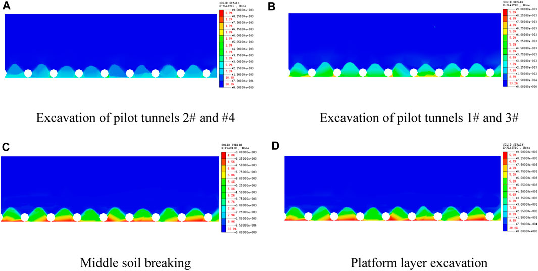
FIGURE 15. Plastic zone of soil around the pipe roof.
From the analysis of the construction stage, as the selected area is located above pilot tunnel #3, after the excavation of pilot tunnels 2# and 4#, the plastic zone of the soil, as shown in Figure 15, is not large, and the plastic stress of the soil is also not large. Furthermore, the soil arching effect is not obvious. Based on the law of surface settlement, the settlement curve is relatively flat at this time. Furthermore, the surface settlement of adjacent points is not much different. After the excavation of pilot tunnels 1# and 3#, the range of the plastic zone expands, the plastic stress increases significantly, and the soil arch effect gradually appears. After the middle soil is broken, the range of plastic zone stops expanding; however, the plastic stress of soil between pipes increases, and the micro soil arch improves the bearing capacity of the surrounding soil and restrains the surface settlement of soil between pipes to some extent. Like for ground settlement, the influence of platform excavation on plastic zone of soil between tubes is small, and the state of the plastic zone does not change significantly.
5 Analysis of influence of transverse pipe roof parameters on ground settlement
5.1 Influence analysis of steel pipe spacing of pipe roof
In order to explore the influence of steel pipe spacing on the surface settlement in a pipe roof, six working conditions with a steel pipe side wall distance of 0.2, 0.5, 0.8, 1.1, 1.4, and 1.7 m are established. The six working conditions are numerically simulated to obtain the transverse surface settlement, which is shown in Figure 16.
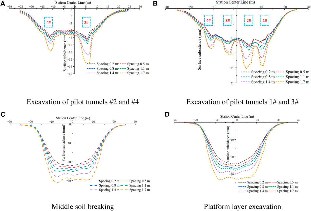
FIGURE 16. Surface subsidence curve under different pipe spacings.
The diagram shows that the pipe roof spacing has the greatest influence on the surface settlement in the excavation area. During the excavation of the pilot tunnel, the soil settlement above the pilot tunnel is quite different. After the excavation of pilot tunnels 2# and 4#, the maximum settlement is 7.7, 8.0, 8.2, 8.9, 12.2, and 14.8 mm for pipe spacings of 0.2, 0.5, 0.8, 1.1, 1.4, and 1.7 m, respectively. Furthermore, compared with that observed with a design spacing of 0.2 m, the surface settlement of steel pipe spacings of 0.5, 0.8. 1.1, 1.4, and 1.7 m increase by 4%, 6.5%, 15.6%, 58.4%, and 92.2% respectively. The soil settlement in the unexcavated area is similar for all pipe spacings. The surface settlement of the unexcavated area between pilot tunnel 2# and pilot tunnel 4# is 5.9, 6.2, 6.4, 6.7, 6.9, and 7.1 mm for pipe spacings of 0.2, 0.5, 0.8, 1.1, 1.4, and 1.7 m, respectively. Compared with that for the design spacing of 0.2 m, the surface settlement of the steel pipe spacings of 0.5, 0.8. 1.1, 1.4, and 1.7 m increase by 5%, 10.2%, 13.6%, 16.9%, and 20.3%, respectively. In the other construction stages, the same law appears in the settlement of the ground surface. After the soil is broken, the overall settlement of the ground surface appears.
The plastic zones for pipe spacings of 0.2, 0.8, 1.4, and 1.7 m are extracted at the same position above pilot tunnel 3# in the same construction stage. The results are shown in Figure 17. The strain evolution of soil layer can be seen by color change. First, as the pipe roof spacing increases, the range of soil plastic zone between pipe roofs and the extension angle increase. As a result, the upward expansion is more considerable. When the spacing is 0.2 m, the plastic zone only develops to the middle of the steel pipe along a certain angle. Under these conditions, the height of the plastic zone is about 0.2 m, and the micro soil arch is located below the side of the pipe roof to restrain the settlement of the upper soil. When the spacing increases to 0.8 m, the extension angle of the plastic zone does not change much, but with an increase in the spacing, the plastic zone exceeds the top of the pipe roof, and its height is about 0.7 m. As shown in Figure 16B, under a pipe spacing of 0.8 m, the surface settlement does not exhibit considerable expansion, and it is not much different from that of the working condition with a pipe spacing of 0.2 m. The pipe roof can still be used to support the micro-soil arch, which limits the surface settlement to a certain extent. When the pipe spacing is 1.4 m, the extension angle of plastic zone is evidently enlarged, the height of plastic zone is about 1.5 m, and the bearing capacity of micro soil arch is gradually weakened. When the spacing is 1.7 m, the plastic zone expands to the middle of the overburden soil, and the soil above the pipe roof also enters the plastic state. In this case, the bearing effect of the pipe roof on the micro soil arch disappears. Furthermore, the surface settlement is 92.2% higher than in the working condition with spacing of 0.2 m.
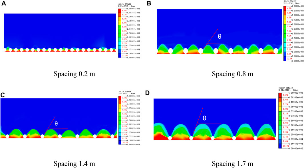
FIGURE 17. Soil plastic zone diagram for different pipe spacings.
The results also reveal that the influence of pipe roof spacing on the surface settlement begins after the excavation of the lower soil, when the pipe roof structure is in a high bearing state. This is because, the larger the pipe spacing, the greater the extension angle of the plastic zone between the pipes, and the more considerable the upward expansion. The soil arch bearing effect gradually reduces, and the pipe roof support effect also reduces.
5.2 Influence analysis of steel pipe length of pipe roof
In order to explore the influence of the length of the embedded soil layer at both ends of the steel pipe in the pipe roof on the surface settlement, five working conditions with constraint lengths of 1, 3, 5, 7, and 9 m at both ends of the steel pipe are established, and the five working conditions are numerically simulated. The lateral surface settlement is shown in Figure 18. The diagram shows that, except for that of the working condition with a constraint length of 1 m at both ends, the surface settlement curves of the other working conditions are not much different in the four construction stages. Taking the excavation process of pilot tunnels 2# and 4# as an example, for the constraint lengths of 1, 3, 5, 7, and 9 m, the maximum surface settlement is 8.3, 7.9, 7.8, 7.75, and 7.7 mm, respectively. Furthermore, under the five working conditions, compared with the design condition, the surface settlement increases or decreases by 5.1%, 1.3%, 1.9%, and 2.5%. Increasing the length of the pipe roof can reduce the surface settlement, but the surface settlement is not obvious. Increasing the stiffness of pipe roof has little effect on ground settlement control (Hu et al., 2018; Cheng et al., 2022).
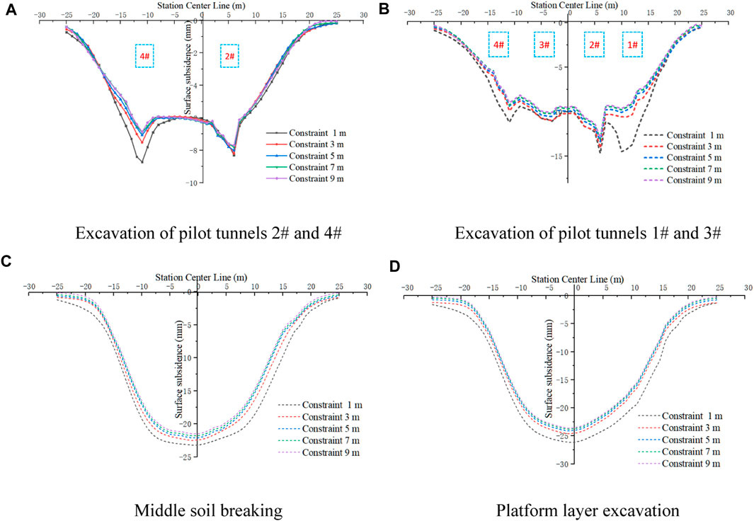
FIGURE 18. Ground surface subsidence curves with different constraint lengths.
In addition, as seen in Figures 18A, B, when the constraint length at both ends is too low, the soil above the side of the pilot tunnel is prone to large deformations during the excavation of the pilot tunnel. After the excavation of pilot tunnels 2# and 4#, there is little difference in the settlement of each working condition above pilot tunnel 2#; however, above pilot tunnel 4#, the surface of the pipe roof with a 1 m constraint at both ends shows significant settlement, and the settlement exhibits an increase of 5%. After the excavation of pilot tunnels 1# and 3#, the settlement of the pipe roof with 1 m constrained at both ends above pilot tunnels 1# and 4# is evidently higher than that in other working conditions, and the constraint ability of the pipe roof is insufficient.
Figure 19 shows the deflection of the pipe roof when the constraints at both ends are 1, 5, and 9 m. First, during the excavation of pilot tunnels 2# and 4#, the maximum settlement when the constraints at both ends are 1 m occurs above pilot tunnel 4#, and the maximum settlement is 7.02 mm, whereas the maximum deflections of the other two working conditions appear above pilot tunnel 2# of the middle pilot tunnel, and the maximum deflection values are 6.8 and 6.74 mm. During the excavation of pilot tunnels 1# and 3#, the maximum deflection value when 1 m is constrained at both ends appears on one side of the side pilot tunnel, and the maximum value is 12.39 mm. The maximum deflections of the working conditions in which 5 and 9 m are constrained at both ends is located above pilot tunnel 3# of the middle pilot tunnel, and the value is 10.6 mm. Together with the deflection cloud diagram of the pipe roof, these results reveal that when the two ends are constrained by 1 m, the binding force at both ends of the pipe roof structure is insufficient, and the end position has a significant overall downward movement. Furthermore, the end settlement is large. When the constraint at both ends exceeds a certain value, the effect of increasing the constraint at both ends on the bearing capacity of the pipe roof is no longer evident or is relatively small.
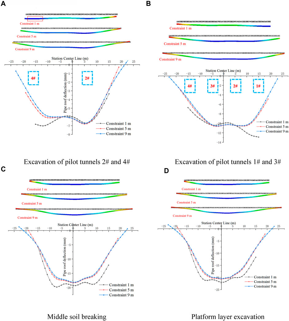
FIGURE 19. Surface subsidence curve under different pipe spacing.
These results reveal that a limiting value for the constraint length at both ends of the pipe roof exists. When the constraint length at both ends of the steel pipe exceeds the limiting value, increasing the constraint length hardly improves the bearing capacity of the pipe roof, and has little effect on the control of surface subsidence. When the constraint length at both ends is insufficient, the excavation process of the pilot tunnel is easy to cause large settlement at the side pilot tunnel.
5.3 Influence analysis of steel pipe stiffness of pipe roof
In order to further explore the influence of steel pipe stiffness on surface settlement in pipe roof structure, the stiffness of standard pipe roof is calculated to be 8,600 kN·m2 by equivalent stiffness method, and the finite element models of steel pipe stiffness of 860, 1,720, 43,000 and 86,000 kN·m2 are established respectively. The corresponding stiffness is 0.1 times, 0.2 times, 5.0 times and 10.0 times of the standard pipe roof respectively. The numerical simulation results are shown in Figures 20, 21.
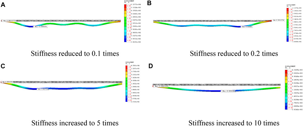
FIGURE 20. Deflection curve of pipe roof under different steel pipe stiffness.
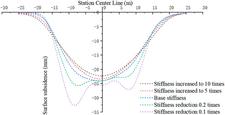
FIGURE 21. Curve of ground settlement under different steel pipe stiffness.
It can be seen from Figure 20 that after the stiffness of the steel pipe in the pipe roof structure exceeds 0.5 times the standard stiffness, the deformation of the pipe roof is U-shaped, the deformation at both ends is small, and the middle deformation is large. The deformation of various working conditions is not much different, and the maximum deformation is 22.7 mm. When the stiffness of the steel pipe is reduced to 0.2 times, the deformation of the pipe roof is wavy, and the maximum deformation is 38.3 mm, an increase of 68.7%. It can be seen from Figure 21 that when the steel pipe stiffness is 0.2 times the standard stiffness, the surface settlement increases significantly. When the stiffness is more than 0.5 times the standard stiffness, the change of surface settlement is not obvious. Therefore, it can be seen that there is a limit value of the stiffness of the pipe roof. When the stiffness reaches the limit value, the bearing capacity of the pipe roof is not significantly improved by increasing the stiffness, which has little effect on the control effect of surface settlement.
6 Conclusion and insights
Compared with the longitudinal pipe roof layout, the transverse pipe roof has high precision control, multi-section simultaneous flow construction, high construction efficiency, and a short construction period. In this paper, the surface settlement law of the transverse pipe roof construction of a shallow buried underground excavation station is studied by field monitoring and numerical simulations, and the different spacings and constraint lengths of the steel pipe in the pipe roof structure are compared. The following conclusions are drawn:
(1) After the pilot tunnel is excavated, the transverse surface settlement is a wavy U-shaped curve. After the soil is broken, the surface settlement curve changes from a wavy U-shaped to a smooth U-shaped curve. After the excavation of pilot tunnel, the longitudinal surface settlement appears jagged, because the surface settlement above the pipe roof is less than that between the pipe roofs.
(2) The numerical simulation reveals the bearing mechanism of the pipe roof. The stress of the pipe roof structure is similar to that of the beam, which has a supporting effect on the stratum. At the same time, the micro soil arch effect appears between the adjacent pipes. The soil arch and the pipe roof structure jointly inhibit the surface settlement.
(3) In the pipe roof structure, the steel pipe spacing affects the soil arching effect. With the increase of steel pipe spacing, the height of soil arching increases, and the bearing capacity of soil arching decreases.
(4) The length and stiffness of the pipe roof affect the bearing capacity of the pipe roof and there is an upper limit. When the length or stiffness of steel tube is low, the bearing capacity of pipe roof structure is low, and the surface settlement increases significantly. When the length and stiffness of the pipe roof exceed its upper limit, increasing the length of the pipe roof or increasing the stiffness of the pipe roof hardly changes the bearing capacity of the pipe roof structure, and the reduction of surface settlement is not obvious.
Data availability statement
The original contributions presented in the study are included in the article/supplementary material, further inquiries can be directed to the corresponding author.
Author contributions
JW: conceptualization, methodology, supervision. XL: conceptualization, writing—original draft. SW: writing—original draft, methodology, and supervision. ZH: data curation, visualization, and supervision. YW: data curation, writing—review and editing.
Funding
The work reported here was supported by the Shandong Provincial Natural Science Foundation, China (No. ZR2020QE265), the Postdoctoral Innovation Project of Shandong Province (No. 202003080), and the China Railway Construction Co., Ltd. 2020 annual scientific research plan project (2020-B05).
Acknowledgments
We are grateful to China Railway Fourteenth Bureau Group Co., Ltd. for providing us with the experimental platform.
Conflict of interest
The authors declare that this study received funding from China Railway Construction Co., Ltd. The funder had the following involvement in the study: the sponsor representatives Wang Zhikang and Liang Erbin provided on-site monitoring data for the study.
Publisher’s note
All claims expressed in this article are solely those of the authors and do not necessarily represent those of their affiliated organizations, or those of the publisher, the editors and the reviewers. Any product that may be evaluated in this article, or claim that may be made by its manufacturer, is not guaranteed or endorsed by the publisher.
References
Al-Naddaf, M., Han, J., and Xu, C. (2019). Experimental investigation of soil arching mobilization and degradation under localized surface loading. J. Geotechnical Geoenvironmental Eng. 145 (12), 04019114. doi:10.1061/(ASCE)GT.1943-5606.0002190
An, Y. L., Zhou, J., Ouyang, P. B., and Li, J. H. (2021). Analysis of tunnel face stability with advanced pipes support. J. Central South Univ. 28 (2), 604–617. doi:10.1007/s11771-021-4625-x
Cai, H. B., Hong, R. B., Xu, L. Y., Cai, C. B., and Rong, C. X. (2022). Frost heave and thawing settlement of the ground after using a freeze-sealing pipe-roof method in the construction of the Gongbei Tunnel. Tunn. Undergr. Space Technol. 125, 104503. doi:10.1016/j.tust.2022.104503
Chen, R. P., Song, X., Meng, F. Y., Wu, H. N., and Lin, X. T. (2022). Analytical approach to predict tunneling-induced subsurface settlement in sand considering soil arching effect. Comput. Geotechnics 141, 104492. doi:10.1016/j.compgeo.2021.104492
Cheng, C., Chen, Y., Zhao, C. Y., Zhao, W., Han, J. Y., Qi, D. Y., et al. (2022). Theoretical analysis of the shield tunnel face stability in dry sandy strata. Eur. J. Environ. Civ. Eng. 2022, 1–21. doi:10.1080/19648189.2022.2062616
Deng, Z. Y., Liang, N. H., Liu, X. R., Fuente, A. D. L., Lin, P., and Peng, H. Y. (2021). Analysis and application of friction calculation model for long-distance rock pipe jacking engineering. Tunn. Undergr. Space Technol. 115, 104063. doi:10.1016/j.tust.2021.104063
Gao, S. L. (2018). Study on the construction mechanical of subway station with flat roof and flat roof. Beijing, China: Beijing Polytechnic University.
Guo, X. Y. (2019). Comparative analysis of mechanical characteristics of construction of transverse tunnel cover method and PBA construction method in subway station. Beijing, China: Beijing Jiaotong University.
Guo, X. Y., Wang, Z. Z., Geng, P., Chen, C. J., and Zhang, J. (2021). Ground surface settlement response to subway station construction activities using pile–beam–arch method. Tunn. Undergr. Space Technol. 108, 103729. doi:10.1016/j.tust.2020.103729
Heng, C. Y., Sun, S., Zhang, J. T., and Zhi, Z. (2022). Calculation method of underground passage excavation on interactive effects among pipe-roof, steel bracing and foundation soil. KSCE J. Civ. Eng. 26 (1), 448–459. doi:10.1007/s12205-021-0500-4
Hu, X. D., Fang, T., Chen, J., and RenGuo, H. W. (2018). A large-scale physical model test on frozen status in freeze-sealing pipe roof method for tunnel construction. Tunn. Undergr. Space Technol. 72, 55–63. doi:10.1016/j.tust.2017.10.004
Ji, X. B., Ni, P. P., Barla, M., Zhao, W., and Mei, G. X. (2018). Earth pressure on shield excavation face for pipe jacking considering arching effect. Tunn. Undergr. Space Technol. 72, 17–27. doi:10.1016/j.tust.2017.11.010
Jia, P. J., Shi, P. X., Guan, Y. P., and Zhao, W. (2021). Calculation model of flexural stiffness of STS structure and parameters optimization. J. Northeast. Univ. Nat. Sci. 42 (08), 1159–1165. doi:10.12068/j.issn.1005-3026.2021.08.014
Li, R., Wang, S. T., Wang, J. F., Zhang, D. L., Chen, P., Pan, H. G., et al. (2022). Mechanical behaviors and supporting effect evaluation of pipe roof in tunneling engineering considering micro-arch effect. Chin. J. Geotechnical Eng. 2022, 1–11. Available at: http://kNs.cnki.net/kcms/detail/32.1124.tu.20220415.1753.011.html.
Liu, D. P., Zhang, D. L., FangSun, Q. Z. Y., Cao, L. Q., and Li, A. (2019). Displacement characteristics of shallow-buried large-section loess tunnel with different types of pre-supports: A case study of new badaling tunnel. Appl. Sci. 10 (1), 195. doi:10.3390/app10010195
Lu, B., Dong, J. C., Zhao, W., Du, X., Cheng, C., Bai, Q., et al. (2022). Novel pipe-roof method for a super shallow buried and large-span metro underground station. Undergr. Space 7 (1), 134–150. doi:10.1016/j.undsp.2021.06.003
Shi, Y. F., Fu, J. Y., Yang, J. S., Xu, C. J., and Deng, D. X. (2021). Performance evaluation of long pipe roof for tunneling below existing highway based on field tests and numerical analysis: Case study. Int. J. Geomechanics 17 (9), 04017054. doi:10.1061/(ASCE)GM.1943-5622.0000933
Song, C. Y., He, W. G., and Fei, M. L. (2022). Study on mechanical characteristics of support system for Shallow-buried Single-Arch subway station in rock stratum. Tunn. Undergr. Space Technol. 124, 104447. doi:10.1016/j.tust.2022.104447
Tao, L. J., Zhang, B., Bian, J., Chen, X. H., and Tian, Z. W. (2018). Test research of pipe roof construction in sand and gravel strata. Constr. Technol. 47 (07), 124–156.
Wang, J. F., Wang, K., Zhang, T., and Wang, S. (2018). Key aspects of a DN4000 steel pipe jacking project in China: A case study of a water pipeline in the shanghai huangpu river. Tunn. Undergr. Space Technol. 72, 323–332. doi:10.1016/j.tust.2017.12.012
Wang, M., Yang, S. S., Du, J. A., and Guo, Y. (2020). Ground surface settlement induced by large diameter jacking-pipe construction in pipe-roof pre-construction method. Adv. Eng. Sci. 52 (4), 8. doi:10.15961/j.jsuese.201900526
Wu, K., and Zhao, Z. S. (2018). Effects of pipe roof support and grouting pre-reinforcement on the track settlement. Adv. Civ. Eng. 2018, 1–9. doi:10.1155/2018/6041305
Xiao, H. J., Zhou, S. H., and Sun, Y. Y. (2019). Stability analysis and case study of shallow tunnel using pipe roof support. Geotechnical Geol. Eng. 37 (3), 1249–1260. doi:10.1007/s10706-018-0681-x
Xie, X. Y., Zhao, M. R., and Shahrour, I. (2019b). Experimental study of the behavior of rectangular excavations supported by a pipe roof. Appl. Sci. 9 (10), 2082. doi:10.3390/app9102082
Xie, X. Y., Zhao, M. R., and Shahrour, I. (2019a). Face stability model for rectangular large excavations reinforced by pipe roofing. Tunn. Undergr. Space Technol. 94, 103132. doi:10.1016/j.tust.2019.103132
Yang, C., Chen, Y. H., Huang, D., and Wang, L. H. (2019). Arching effect between the pipes of a pipe umbrella support system in a shallow-buried tunnel. KSCE J. Civ. Eng. 23 (12), 5215–5225. doi:10.1007/s12205-019-5197-2
Zarei, H., Moarefvand, P., and Salmi, E. F. (2019). Numerical modeling of umbrella arch technique to reduce tunnelling induced ground movements. Environ. Earth Sci. 78 (10), 291. doi:10.1007/s12665-019-8302-4
Zhang, D. M., Chen, C. C., and Zhang, D. M. (2022). Ground surface movement of Shallow-Buried Large-Sectional tunnel under Full-Ring Pipe-Jacking roof and ground freezing. Tunn. Undergr. Space Technol. 127, 104600. doi:10.1016/j.tust.2022.104600
Zhang, P., Behbahani, S. S., Ma, B. S., Lseley, T., and Tan, L. X. (2018). A jacking force study of curved steel pipe roof in Gongbei tunnel: Calculation review and monitoring data analysis. Tunn. Undergr. Space Technol. 72, 305–322. doi:10.1016/j.tust.2017.12.016
Keywords: pipe roof, surface subsidence, soil arch effect, plastic zone, underground excavation station
Citation: Wang J, Li X, Wu S, He Z and Wei Y (2023) Field test and numerical simulation of ground settlement in super shallow buried station excavation supported by transverse pipe roof. Front. Earth Sci. 11:1136270. doi: 10.3389/feart.2023.1136270
Received: 02 January 2023; Accepted: 13 February 2023;
Published: 01 March 2023.
Edited by:
Hai Lin, Nanchang University, ChinaReviewed by:
Narendra Kumar Samadhiya, Indian Institute of Technology Roorkee, IndiaCelestino González Nicieza, University of Oviedo, Spain
Copyright © 2023 Wang, Li, Wu, He and Wei. This is an open-access article distributed under the terms of the Creative Commons Attribution License (CC BY). The use, distribution or reproduction in other forums is permitted, provided the original author(s) and the copyright owner(s) are credited and that the original publication in this journal is cited, in accordance with accepted academic practice. No use, distribution or reproduction is permitted which does not comply with these terms.
*Correspondence: Shengzhi Wu, d3VzaGVuZ3poaTE5QHNkanp1LmVkdS5jbg==