 Peng Xiang
 Hong Guang Ji1
95% of researchers rate our articles as excellent or good
Learn more about the work of our research integrity team to safeguard the quality of each article we publish.
Find out more
ORIGINAL RESEARCH article
Front. Earth Sci. , 24 January 2023
Sec. Geohazards and Georisks
Volume 11 - 2023 | https://doi.org/10.3389/feart.2023.1126764
This article is part of the Research Topic Geological Disasters in Deep Engineering: Mechanism, Warning, and Risk Mitigation, volume II View all 11 articles
To address the challenge of designing grouting reinforcement in a deep shaft to control water, this study established an elastic-plastic analytical formula for the grouted rock surrounding a shaft under the combined action of thermal, hydraulic, and mechanical fields based on the Mohr–Coulomb yield criterion. The various rules and influencing factors of stability and impermeability of the grouted rock surrounding the shaft are calculated and analyzed. The analysis shows that damage to the surrounding rock is aggravated by the action of high ground temperature and high water pressure in deep shafts, and the influence of water pressure is particularly significant. The larger the radius and cohesion of the grouted surrounding rock, the smaller the radius of its plastic zone. With an increase in the elastic modulus ratio between the grouted surrounding rock and the original rock, the radius of its plastic zone increases, so the elastic modulus of the grouted surrounding rock design should consider the original surrounding rock. With a decrease in the permeability coefficient of the grouted surrounding rock, the radial stress decreases, the tangential stress increases, and the radius of the plastic zone increases. The development of plastic zone not only affects the stability but also causes an increase in the permeability coefficient. There is mutual restriction and influence between the shaft water inflow, the permeability coefficient, the radius of the grouted surrounding rock, and the radius of its plastic zone. In the design of grouting reinforcement, the stability of surrounding rock and the control requirements of shaft water inflow should be comprehensively considered and the optimal parameters should be selected based on theoretical calculation. This study provides a theoretical basis for the optimization of grouting reinforcement parameters in a deep shaft.
With the continuous promotion of the strategy of seeking mineral resources and energy in deep mines, the construction depth of mine shafts has exceeded 1500 m in China and will soon exceed 2000 m. For example, the design depth of the main shaft in the Sanshandao Gold Mine under construction in the Xiling mining area is more than 2000 m. Existing research results (Xiang et al., 2022a; Xiang et al., 2022b) show that the in situ stress at a depth of 2000 m is as high as 70 Mpa, the water head pressure is close to 20 Mpa, and the temperature exceeds 60 °C. Disasters caused by high stress, high water pressure, and high temperature environments are the biggest challenges faced by the deep shaft project, of which the water hazard is the most prominent, and the pregrouting reinforcement of the surrounding rock in the working face is the main means of controlling water hazards at present. After grouting, the surrounding rock must meet impermeability requirements, and the surrounding rock’s stability should not be ignored during shaft excavation.
In terms of theoretical research on the grouting reinforcement of the rock surrounding shafts, Zhang Dingli et al. put forward a new design concept of active waterproofing and drainage control and established an overall seepage mechanical model including the reinforcement area and the primary support. They clearly show that the reinforcement area and the primary support are locations where water inflow is controlled (Li et al., 2012; Zhang and Sun, 2019). Song Zhiheng et al. studied the influence of the grouted reinforcement area of a tunnel on the water inflow velocity and optimized the grouting parameters according to the numerical simulation results. Yang et al. (2017) carried out an experimental study on the influence of a grouted reinforcement area on the seepage field, and the results show that the grouted reinforcement area can bear part of the underground load and effectively reduce tunnel drainage. Li et al. (2013) established a simplified seepage model of a shaft in an infinite aquifer and analyzed and verified the influence of grouting reinforcement parameters on the external water pressure of the lining. Li et al. (2020) studied the influence of grouting reinforcement parameters on the seepage field of the surrounding rock under different waterproof and drainage types of tunnels using theoretical analysis and numerical simulation methods. Zhou et al. (2020) deduced the analytical solutions of the Darcy seepage field, the non-Darcy seepage field, and the effective stress field of the rock surrounding the tunnel and analyzed the influence of the grouting effect on the seepage and stress fields of the surrounding rock (He et al., 2020).
There have been many theoretical achievements in analytical solutions research on the stability of a circular chamber. One achievement is the elastoplastic analytical theory based on the mechanics of a circular hole in an infinite plane without considering the effects of water and temperature (Ren and Qiu, 2005; Xiao et al., 2013; Chen et al., 2017; Ma et al., 2021). Another achievement is the elastoplastic analytical theory considering the “fluid solid” coupling of groundwater or the “thermal” coupling of ground temperature (Rong and Cheng, 2004; Li et al., 2004; Shi et al., 2008; Carranza-Torres and Zhao, 2009; Lü and Xu, 2009; Xu et al., 2015; Xu et al., 2020; Jin et al., 2022). In addition, an analytical theory considers the interaction of thermal, hydraulic, and mechanical fields (Kong et al., 2005; Bai, 2011; Pandey et al., 2017; Liu et al., 2019), but most of them only involve elastic problems and cannot be directly used in the stability analysis of underground caverns. Zhang Yujun et al. established an elastic-plastic analytical solution for a circular cavern under the combined action of thermal, hydraulic, and mechanical fields but did not consider the effect of grouting (Zhang and Zhang, 2013).
To sum up, most existing research focuses on tunnel engineering, but there is little discussion of the grouting reinforcement and seepage resistance of a 2000-m deep shaft under the combined action of high stress, high water pressure, and high temperature. Therefore, in this article, an elastic-plastic analytical solution of the surrounding rock reinforced by grouting under the combined action of high stress, high water pressure, and high temperature is established, and the variation law and influencing factors of the stability and impermeability of reinforced rock in a deep shaft are analyzed, providing a theoretical basis for the design and optimization of parameters of deep grouting reinforcement.
Due to the high water pressure in the deep stratum, it is very difficult to control water once the water-bearing fractured stratum is exposed during shaft excavation. Therefore, the rock surrounding the working face is usually pregrouted to prevent seepage and block water; that is, the water-bearing fractured stratum is first grouted and consolidated, and then, blasting excavation is carried out.
First, the mechanical model of grouting the rock surrounding a deep shaft under the combined action of thermal, hydraulic, and mechanical forces is simplified into a stable plane model, as shown in Figure 1. The model can be regarded as the problem of steady heat conduction and steady seepage of a double-layered ring composed of the grouted reinforcement area and the original surrounding rock, which is a plane strain problem.In this model,

FIGURE 1. Mechanical model of surrounding rock reinforced by grouting in shaft.
It is assumed that the permeability coefficient of the material in the aforementioned model is the same in all directions, the seepage direction is mainly radial, and the buoyancy in the seepage volume force has little influence and can be ignored. Therefore, this problem can be simplified as an axisymmetric stable seepage problem. The second-order ordinary differential equation of the stable seepage field formed after grouting reinforcement is as follows:
The distribution law of water pressure in the seepage field of surrounding rock reinforced by grouting is as follows (He et al., 2020):
where
Assuming that the thermal conductivity of the material in the above model is the same in all directions and the thermal conductivity direction is mainly radial, the problem is simplified as an axisymmetric steady-state heat conduction problem. The second-order ordinary differential equation of the steady-state temperature field is as follows (Xu, 2006):
The distribution law of the temperature field of surrounding rock reinforced by grouting can be obtained as follows:
where
Research shows that under the action of higher temperature, 0.4–0.45 MPa thermal stress can be generated in the rock mass when the temperature changes by 1
Then, the distribution law of thermal stress expression of shaft-surrounding rock is obtained as follows:
where
Assuming that the rock surrounding the grouting and surrounding rock mass are homogeneous, ignoring the dead weight of the element, and only considering the unidirectional coupling of thermal stress and seepage stress to the stress field, this study is conducted according to the axisymmetric plane strain problem, and the equilibrium differential equation is as follows (ZHANG and ZHANG, 2013):
where
To achieve the effect of water blocking, the range of grouting reinforcement must be larger than the damage and failure area of the surrounding rock during actual excavation, so only the plastic failure area in the reinforcement body must be analyzed.
In order to achieve the effect of water plugging, the range of the grouted reinforcement area must be larger than the damage zone of the surrounding rock during the actual excavation, so it is only necessary to analyze the case that the plastic zone is within the scope of reinforcement. As shown in Figure 1,
where
It is assumed that the grouted surrounding rock meets the Mohr–Coulomb criterion after entering the plastic state, and the tangential stress is the first principal stress during excavation; that is,
where
Substitute Eq. 9 into Eq. 8 to get
The stress in the yield zone can be solved using Eq. 10 as follows:
where B is the integral constant, and the expression of A is as follows:
By substituting the boundary condition
The equilibrium differential equation of the microelement in the elastic zone of the grouted reinforcement area is the same as Eq. 8, and the boundary condition is
The differential equation of stress balance in the elastic zone of the original surrounding rock is consistent with Eq. 8, and only the parameter
The boundary condition is
According to the stress and displacement expressions derived previously, the elastoplastic solution can be obtained by introducing the initial values and boundary conditions. At the elastic-plastic interface of the reinforced surrounding rock,
At the elastic-plastic interface of the reinforced surrounding rock, the radial stress shall also meet the following requirements:
In addition, the displacement continuity condition of the contact surface between the original surrounding rock and the reinforced surrounding rock can be obtained as follows:
Combining the aforementioned three groups of equations, a transcendental equation about
In order to further analyze the influencing factors of stability and impermeability of surrounding rock reinforced by grouting, the following is illustrated by the specific calculation of an example. Taking a metal mine shaft of 2000 m depth in the Laizhou area of Shandong Province in China as an example, according to the mine survey and design data, the basic parameters of the shaft model at 2000m depth are as follows:
The grouted surrounding rock:
The original surrounding rock:
The shaft diameter and initial boundary conditions are as follows:
Based on the aforementioned parameters and through variable analysis, the influence law of each parameter on the performance of the grouting reinforcement area can be obtained.
Figure 2 shows the distribution of the radial stress and tangential stress of the surrounding rock under four conditions. It can be seen from the analysis that the radius of the plastic zone is the largest under the combined action of thermo-hydro-mechanical forces, the second largest is under the action of hydro-mechanical forces, the third largest is under the action of thermo-mechanical forces, and the smallest is under the action of mechanical forces alone. It can be seen that the surrounding rock damage is significantly exacerbated by the high temperature and high water pressure of the deep stratum, and the effect of water is significantly greater than that of temperature. Tangential stress jumps at the contact surface between the grouted rock surrounding the shaft and the original rock.
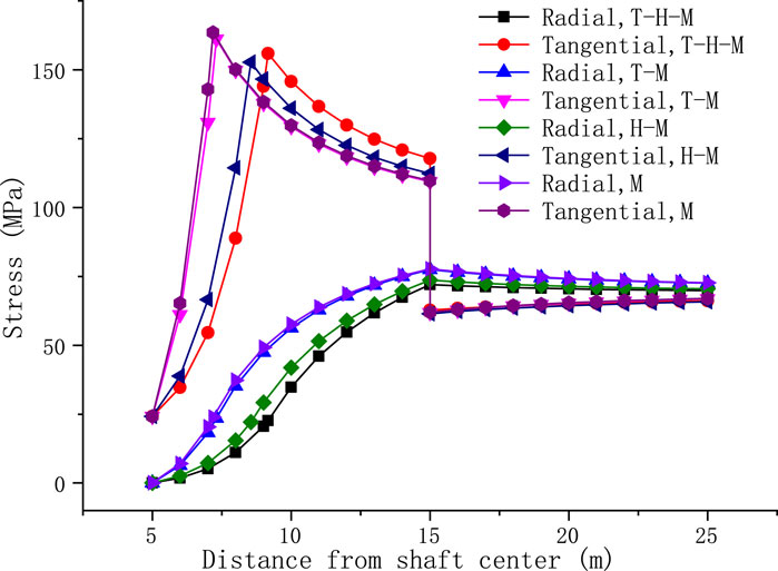
FIGURE 2. Stress distribution of surrounding rock under the combination of thermo-hydro-mechanical forces.
In the legend, T represents temperature, H represents hydraulic, and M represents mechanical.
Figure 3 shows that the radius of the plastic zone of the grouted surrounding rock decreases with the increase of the radius of the grouted area and surrounding rock. When the radius of grouted area exceeds a certain limit (about twice the radius of the plastic zone), the plastic zone does not change. When the radius of the grouted surrounding rock is equal to the radius of the plastic zone, the critical radius of the grouted surrounding rock can be obtained. When the radius of the grouted surrounding rock is greater than the critical value, the radius of the plastic zone decreases with an increase in the grouted reinforcement radius. When the radius of the grouted reinforcement is less than the critical value, the plastic damage range will exceed the reinforcement area. Therefore, the critical value can be used as a reference standard for the stability design of grouted surrounding rock. In addition, the higher the in situ stress, the larger the radius of the plastic zone of the corresponding reinforcement.
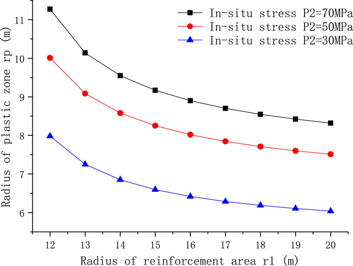
FIGURE 3. Effect of reinforcement area radius on plastic zone radius.
Figure 4 shows that the radius of the plastic zone increases with the increase of initial water pressure. The larger the water pressure, the greater the rate of plastic zone increase. With an increase in the temperature difference between the wellbore and the original formation, the radius of the plastic zone in the reinforcement area increases. Due to the limited change of temperature, its impact on the plastic zone is much weaker than the water pressure.
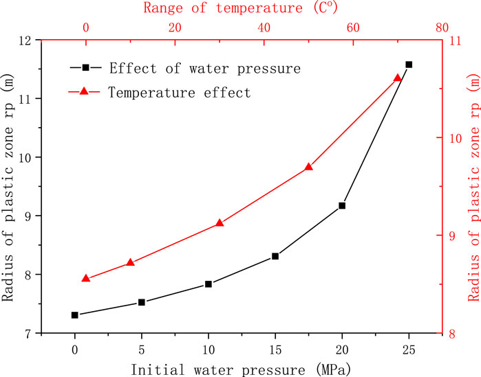
FIGURE 4. Effect of initial water pressure and temperature on plastic zone radius.
Figure 5 shows that the radius of the plastic zone decreases with the increase of the cohesive force of the grouted surrounding rock. Increasing the cohesive force of the grouted surrounding rock has an obvious effect on improving its failure. In addition, the radius of the plastic zone increases with the increase of the elastic modulus of the surrounding rock. The higher the elastic modulus of the original surrounding rock, the smaller the radius of the plastic zone is. It can be seen that the elastic modulus of the original surrounding rock has a great influence on the plastic zone of the grouted surrounding rock. In a word, the radius of the plastic zone increases with the increase of the elastic modulus ratio of the grouted surrounding rock and the original rock.
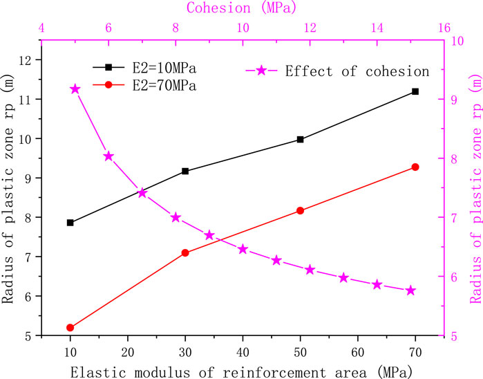
FIGURE 5. Effect of elastic modulus and cohesion on plastic zone radius.
From the aforementioned analysis, it can be seen that too large an elastic modulus of surrounding rock reinforcement is not necessarily beneficial. To analyze the causes, Figure 6 shows the distribution of the surrounding rock stress field under two conditions. The first condition is that the elastic modulus of the grouted surrounding rock is greater than that of the original surrounding rock, which usually corresponds to the condition that the thickness of the surrounding rock fracture zone is large. After the rock surrounding the shaft is grouted, the surrounding rock in the distance is still a broken area, and the elastic modulus is relatively low. At this time, the stress after shaft excavation is mainly concentrated in the grouted surrounding rock. The stress in the grouted surrounding rock is much higher than that in the original surrounding rock, and its plastic damage range is also large. The second condition is that the elastic modulus of the grouted surrounding rock is smaller than that of the original surrounding rock, which usually corresponds to a small thickness of the fracture zone. At this time, the grouting reinforcement covers the entire fracture zone, and the surrounding rock in the distance is a relatively complete original stratum with a relatively large elastic modulus. In this case, the stress after shaft excavation is mainly concentrated in the original surrounding rock, and the stress concentration in the grouted surrounding rock is relatively small, which greatly reduces the plastic damage range. It can be seen that the jumping direction of the maximum tangential stress is related to the elastic modulus ratio of the grouted surrounding rock and the original surrounding rock. When the elastic modulus of the grouted surrounding rock is greater than the original surrounding rock, the maximum tangential stress appears at the elastoplastic interface; otherwise, it appears at the contact surface between the grouted surrounding rock and the original rock. The distribution of the plastic zone of the grouted surrounding rock is closely related to the surrounding rock characteristics. The elastic modulus design of the grouted surrounding rock should consider the original surrounding rock conditions, especially the bearing role of the original surrounding rock.
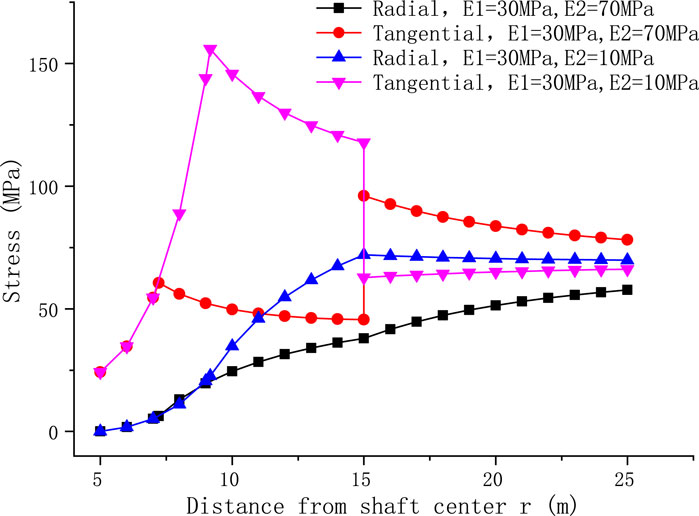
FIGURE 6. Effect of elastic modulus of original surrounding rock on stress field.
Figure 7 shows that with an increase in shaft support pressure, the plastic zone decreases significantly. It can be seen that timely support during excavation has a good effect on reducing the damage to the grouted surrounding rock. The larger the permeability coefficient ratio of the original surrounding rock and the grouted surrounding rock, the larger the plastic zone radius is. When the coefficient ratio exceeds 40, the change in the plastic zone tends to ease. Figure 8 shows that when the permeability coefficient of the original rock is unchanged, the radial stress of the surrounding rock decreases with the reduction of the permeability coefficient of the grouted surrounding rock, and the tangential stress increases, leading to more plastic failure of the rock. Therefore, increasing the permeability coefficient of the grouted surrounding rock can reduce the radius of the plastic zone, which is beneficial to the stability of the surrounding rock. However, the increase in the permeability coefficient will also lead to an increase in the water inflow of the shaft. Therefore, the design of the permeability coefficient must comprehensively consider the surrounding rock stability and water inflow control requirements.
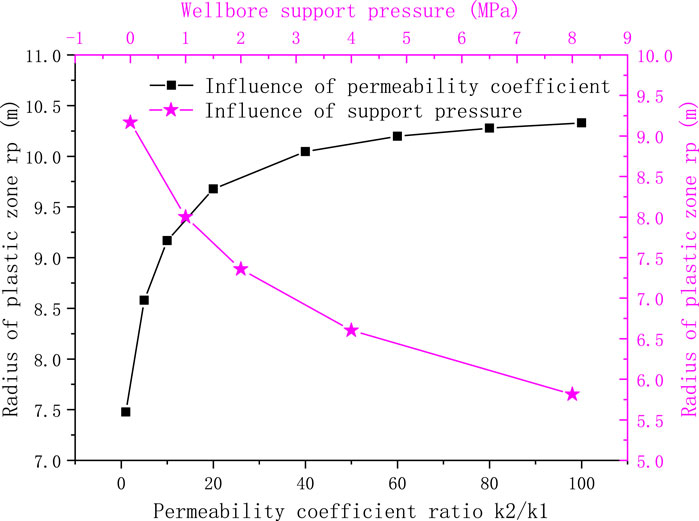
FIGURE 7. Variation of plastic zone radius with support pressure and the permeability coefficient ratio.
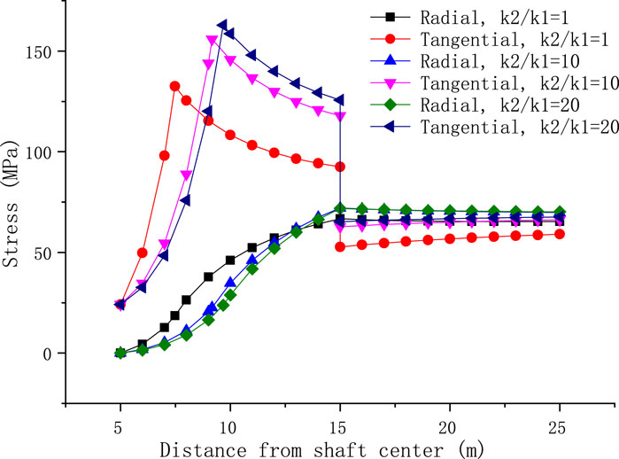
FIGURE 8. Stress distribution under different permeability coefficient ratios.
When the shaft is excavated, due to the plastic failure of some grouted surrounding rock near the shaft center, its permeability characteristics will also change. Assuming that the permeability coefficient of the plastic zone is infinite, that is, the water pressure at the elastic-plastic interface of the reinforcement surrounding rock is zero and the force of the blocked water is mainly borne by the elastic zone of the grouted surrounding rock, the expression of water pressure in the elastic zone of the grouted surrounding rock can be obtained according to Formula (2):
The expression of wellbore water inflow can be obtained using Darcy’s law (Zhou et al., 2020):
where
It can be seen that the water inflow of the shaft is related to the permeability coefficient of the rock mass, the radius of the grouted surrounding rock, and the radius of the plastic zone. The radius of the grouted surrounding rock is r1. The value should consider both the thickness of the plastic zone and the control requirements of the water inflow of the shaft. The grouting reinforcement radius considering the influence of the plastic zone can be obtained by combining Eqs 27–29, 31. Taking the water inflow control at a depth of 2000 m of the metal mine shaft as an example, the thickness of the aquifer is 10 m. The calculation results are shown in Table 1. With the increase of the standard value q of water inflow control, the requirements for the grouting reinforcement radius decrease accordingly. When the influence of the plastic zone is not considered (
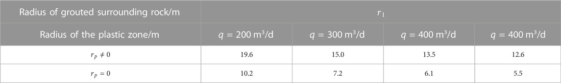
TABLE 1. Relationship between water inflow, radius, and plastic zone of grouted surrounding rock.
(1) Compared with considering the effect of in situ stress only, the damage to the surrounding rock is significantly exacerbated by the high temperature and high water pressure of the deep stratum, and the effect of water is significantly greater than that of temperature. Tangential stress jumps at the contact surface between the grouted surrounding rock and the original rock, and the direction of the stress jump is related to the ratio of elastic modulus of the two. When the elastic modulus of the grouted surrounding rock is greater than the original surrounding rock, the maximum tangential stress appears at the elastoplastic interface; otherwise, it appears at the contact surface between the grouted surrounding rock and the original rock.
(2) The radius of the plastic zone of the grouted surrounding rock decreases with the increase of the radius of the grouted surrounding rock. When the radius of the grouted surrounding rock exceeds roughly twice that of the plastic zone, the plastic zone does not change. With the increase of the in situ stress, water pressure, and temperature difference, the corresponding radius of the plastic zone of the grouted surrounding rock increases.
(3) The radius of the plastic zone decreases with an increase in the cohesion in the surrounding rock. With an increase in the elastic modulus ratio between the grouted surrounding rock and the original rock, the radius of the plastic zone increases. When designing the elastic modulus of the grouted surrounding rock, the original surrounding rock should be considered to give full play to the stress-bearing role of the original surrounding rock.
(4) Increasing the permeability coefficient of the grouted surrounding rock can reduce the radius of the plastic zone, which is beneficial to the stability of the surrounding rock, but it will also lead to an increase in water inflow. The water inflow of the shaft, the permeability coefficient of the grouted surrounding rock, the radius of the grouted surrounding rock, and the radius of the plastic zone are all interrelated. Therefore, the grouting reinforcement parameters should be designed based on the stability of the surrounding rock and water inflow control requirements, and the optimal solution should be selected through theoretical calculation.
Due to the author’s mathematical and mechanical level, this article does not consider the complete coupling effect of thermal, hydraulic, and mechanical fields. Whether the Mohr–Coulomb criterion can truly reflect the failure characteristics of surrounding rock in deep strata remains to be discussed. In addition, the interaction between the surrounding rock reinforced by grouting and the shaft wall structure needs further study.
The raw data supporting the conclusion of this article will be made available by the authors without undue reservation.
PX and HJ contributed to the conception and design of the study. PX wrote the first draft of the manuscript. HJ, GZ, and WL wrote sections of the manuscript. All authors contributed to the manuscript revision, and read and approved the submitted version.
This paper was supported by the Major Scientific and Technological Innovation Project of Shandong Province (No. 2019SDZY05) and the Open Fund of the Hubei Provincial Engineering Technology Research Center of High Efficient Clean Utilization Shale Vanadium Resource (No. 2021zy003).
Author WL was employed by the Sanshandao Gold Mine of Shandong Gold Group Co., Ltd., China.
The remaining authors declare that the research was conducted in the absence of any commercial or financial relationships that could be construed as a potential conflict of interest.
All claims expressed in this article are solely those of the authors and do not necessarily represent those of their affiliated organizations, or those of the publisher, the editors and the reviewers. Any product that may be evaluated in this article, or claim that may be made by its manufacturer, is not guaranteed or endorsed by the publisher.
Bai, B. (2011). Analytical solutions of thermal consolidation for a hollow cylinder saturated porous medium. Rock Soil Mech. 32 (10), 2901–2916. doi:10.16285/j.rsm.2011.10.005
Carranza-Torres, C., and Zhao, J. (2009). Analytical and numerical study of the effect of water pressure on the mechanical response of cylindrical lined tunnels in elastic and elasto-plastic porous media. Int. J. Rock Mech. Min. Sci. 46 (3), 531–547. doi:10.1016/j.ijrmms.2008.09.009
Chen, L., Mao, X. B., Li, M., and Chen, Y. L. (2017). Elastic-plastic analysis of deep roadway fracture surrounding rock based on drucker-prager criterion. Chin. J. Coal 42 (2), 484–491. doi:10.13225/j.cnki.jccs.2016.6029
He, M. C. (2004). Present state and perspective of rock mechanics in deep mining engineering. Proceeding of the 8th Rock Mechanics and Engineering Conference, Beijing (Beijing: Science Press), 88–94. doi:10.19721/j.cnki.1001-7372.2020.12.016
He, X., Zhou, X. M., Guo, X. H., Xu, Y., and Ma, W. Z. (2020). Analysis of non-Darcy seepage field and stress field of surrounding rock strengthened by grouting in deep buried tunnel. China J. Highw. Transp. 33 (12), 200–211. doi:10.19721/j.cnki.1001-7372.2020.12.016
Jin, B., Hu, M., and Fang, Q. H. (2022). Research on stress field of surrounding rock and lining structure of deep-buried subsea tunnel considering seepage effect. Chin. J. Theor. Appl. Mech. 54 (5), 1322–1330. doi:10.6052/0459-1879-21-670
Kong, X. Y., Li, D. L., Xu, X. Z., and L, D. T. (2005). Study on the mathematical models of coupled thermal-hydrological mechanical (THM) processes. Chin. J. Hydrodynamics 20 (2), 269–275. doi:10.16076/j.cnki.cjhd.2005.02.02
Li, P. F., Zhang, D. L., Zhao, Y., and Zhang, C. P. (2012). Study on water pressure distribution of composite lining of submarine tunnel and parameters of grouting reinforcement ring. Chin. J. Rock Mech. Eng. 31 (2), 280–288. doi:10.3969/j.issn.1000-6915.2012.02.007
Li, Z. L., Ren, Q. W., and Wang, Y. H. (2004). Elastic-plastic analytical solution of deep-buried circle tunnel considering fluid flow field. Chin. J. Rock Mech. Eng. 23 (8), 1291–1295. doi:10.3321/j.issn:1000-6915.2004.08.011
Li, W., Yang, D., and Qing, L. I. (2013). Study on the characteristic of water pressure upon lining in subject to high hydraulic pressure mountain tunnel. J. Railw. Eng. Soc. (11), 57–62. doi:10.3969/j.issn.1006-2106.2013.11.011
Li, L. Y., Yang, J. S., Gao, C., Xia, W. Y., and Ma, Y. N. (2020). Analytical study on seepage field of tunnels with external drainage considering effect of grouting rings. Chin. J. Geotechnical Eng. 42 (1), 133–141. doi:10.11779/CJGE202001015
Liu, G. H., Pu, H., Zhao, Z. Z., and Liu, Y. (2019). Coupled thermo-hydro-mechanical modeling on well pairs in heterogeneous porous geothermal reservoirs. Energy 171, 631–653. doi:10.1016/j.energy.2019.01.022
Lü, X., and Xu, J. (2009). Elastic-plastic solution for subsea circular tunnel under the influence of seepage field. Eng. Mech. 26 (2), 216–221.
Ma, Y., Lu, A., Cai, H., and Zeng, X. (2021). Analytical solution for determining the plastic zones around two unequal circular tunnels. Tunn. Undergr. Space Technol. 120, 104267. doi:10.1016/j.tust.2021.104267
Pandey, S. N., Chaudhuri, A., and Kelkar, S. (2017). A coupled thermo-hydro-mechanical modeling of fracture aperture alteration and reservoir deformation during heat extraction from a geothermal reservoir. Geothermics 65 (1), 17–31. doi:10.1016/j.geothermics.2016.08.006
Ren, Q. W., and Qiu, Y. (2005). Elastic-plastic solution of circular tunnel with liner. Eng. Mech. 22 (2), 212–217.
Rong, C. X., and Cheng, H. (2004). Stability analysis of rocks around tunnel with ground water permeation. Chin. J. Rock Mech. Eng. 23 (5), 741–744. doi:10.3321/j.issn:1000-6915.2004.05.007
Shi, Y., Zhu, Z. D., and Li, Z. J. (2008). Deformation characteristics of deep-buried caverns considering thermal effect. Adv. Sci. Technol. Water Resour. 28 (3), 33–36.
Xiang, P., Ji, H. G., Geng, J. M., and Zhao, Y. W. (2022). Characteristics and mechanical mechanism of in situ unloading damage and core discing in deep rock mass of metal mine. Shock Vib. 2022, 1–13. doi:10.1155/2022/5147868
Xiang, P., Xu, H. C., Ji, H. G., Li, Q., and Wang, H. (2022). Thermal property of granite in deep strata and its effect on thermal zone of surrounding rock. Shock Vib. 2022, 1–9. doi:10.1155/2022/2461684
Xiao, J. Q., Feng, X. T., Zhang, L. C., Qiu, S. L., et al. (2013). Static elastoplastic analytical method of circular tunnel under uniform geostress field. Chin. J. Rock Mech. Eng. 32 (S2), 3466–3477. doi:10.3969/j.issn.1000-6915.2013.z2.061
Xu, Y., Zou, J. F., Xu, Y., and Yuan, Z. (2015). Generalized Hoek-Brown solution for circular tunnel with axial and osmotic forces considered. Rock Soil Mech. 36 (10), 2837–2846+2854. doi:10.16285/j.rsm.2015.10.013
Xu, Y., Zhou, X. M., He, X. N., Wu, T., Zhang, J. L., and Li, S. (2020). Thermal-solid coupling analysis of shaft wall and surrounding rocks in a mine shaft. Rock Soil Mech. 41 (S1), 217–226+245. doi:10.16285/j.rsm.2019.0744
Yang, S. Z., He, C., Li, Z., Yang, W. B., and Luo, Y. W. (2017). Inner water pressure distribution law of the tunnel grouting circle in water-rich area. J. China Univ. Min. &Technology (3), 546–553. doi:10.13247/j.cnki.jcumt.000684
Yue, H., Su, Y., and Fang, Y. (2017). An analysis of the temperature effect of irregular failure in deep rock mass. Hydrogeology Eng. Geol. 44 (01), 48–56. doi:10.16030/j.cnki.issn.1000-3665.2017.01.08
Zhang, D., and Sun, Z. (2019). An active control waterproof and drainage system of subsea tunnels and its design method. Chin. J. Rock Mech. Eng. 38 (1), 1–17. doi:10.13722/j.cnki.jrme.2018.0955
Zhang, Y. J., and Zhang, W. Q. (2013). An elastoplastic analytical solution for circular cavern considering combined thermos-hydro-mechanical action. Rock Soil Mech. 34 (S2), 41–44.
Keywords: deep shaft, grouting reinforcement, elastoplastic solution, stability, water inflow
Citation: Xiang P, Ji HG, Zhang GQ and Li WG (2023) Theoretical analysis of grouting reinforcement for surrounding rock of deep shaft based on stability and water inflow control. Front. Earth Sci. 11:1126764. doi: 10.3389/feart.2023.1126764
Received: 18 December 2022; Accepted: 09 January 2023;
Published: 24 January 2023.
Edited by:
Lijie Guo, Beijing Mining and Metallurgy Technology Group Co., Ltd., ChinaCopyright © 2023 Xiang, Ji, Zhang and Li. This is an open-access article distributed under the terms of the Creative Commons Attribution License (CC BY). The use, distribution or reproduction in other forums is permitted, provided the original author(s) and the copyright owner(s) are credited and that the original publication in this journal is cited, in accordance with accepted academic practice. No use, distribution or reproduction is permitted which does not comply with these terms.
*Correspondence: Peng Xiang, eGlhbmdwZW5nODExQDEyNi5jb20=
Disclaimer: All claims expressed in this article are solely those of the authors and do not necessarily represent those of their affiliated organizations, or those of the publisher, the editors and the reviewers. Any product that may be evaluated in this article or claim that may be made by its manufacturer is not guaranteed or endorsed by the publisher.
Research integrity at Frontiers
Learn more about the work of our research integrity team to safeguard the quality of each article we publish.