 Jiangshuai Wang1
 Chuchu Cai
 Song Deng
- 1School of Petroleum and Natural Gas Engineering, Changzhou University, Changzhou, China
- 2CNPC Research Institute of Engineering Technology Co., Ltd., Beijing, China
- 3National Engineering Research Center for Oil and Gas Drilling and Completion Technology, Beijing, China
Among the existing gas storage facilities, salt cavern gas storage has the advantages of high injection production efficiency, low gas cushion volume, safety, flexibility, etc. It is of great significance to speed up the construction of underground gas storage by transforming abandoned salt caverns of salt industry into underground gas storage. However, old salt cavern wells cannot be directly converted into gas storage injection and production wells, so the old wellbore must be plugged to ensure the effectiveness of plugging. Therefore, a set of plugging optimization technology for salt cavern gas storage wells is urgently needed. In this paper, a 3D finite element model of the cement plug-formation system based on cohesive element method is established for the milling and plugging of the old well in the salt cavern gas storage section. The results show that under the condition of constant gas storage pressure, a certain degree of small deformation will occur at the bottom of the cement plug after compression, resulting in the shear direction deformation of the cement plug formation cementation interface, and peeling will occur after accumulation to a certain extent. With the increase of simulation time, the length of stripping section gradually increases and tends to be stable, and reaches the limit of stripping failure length. In the process of research, the factors and laws affecting the stripping failure length were also analyzed. It was found that the stripping failure length of cement plug formation cementation interface was related to the maximum operating pressure of gas storage, cement plug length, cement plug diameter, elastic modulus, Poisson’s ratio and other factors. The research results are helpful to judge whether the milling and plugging length of the old well section is sufficient, and provide theoretical guidance for ensuring the long-term safe operation of the gas storage.
1 Introduction
China’s natural gas demand is increasing year by year, and the contradiction between supply and demand is becoming increasingly prominent. The construction of the gas storage is a key task for the development of China’s natural gas industry (Shi et al., 2017; Dong et al., 2021). Salt cavern gas storage is considered the safest way to store large quantities of hydrocarbons. The transformation of abandoned salt caverns from salt-production industries into Underground Gas Storages (UGS) has a great significance for the full utilization of salt mine resources and accelerating the construction of UGS (Bai S et al., 2022). Among the existing storage facilities, salt cavern underground gas storage has greater advantages with the characteristics of high injection-production efficiency, low cushion gas, volume, safety, and flexibility (Pamucar et al., 2020; Pinto et al., 2021). It is much safer in terms of safety and environmental protection: salt rock has extremely low permeability and better damage resistance and self-healing ability, which is a sealing material to ensure energy storage (Bérest and Brouard, 2003; Cornet et al., 2018). Although salt cavern reservoir has obvious advantages in energy storage, its complex geological conditions, lack of practical experience and imperfect theoretical system pose a great challenge to the sealing ability of salt cavern gas storage. There have been gas leaks due to the failure of the gas storage seal. Casing damage and cap fracture are the main causes of these accidents (Sovacool, 2008; Jing et al., 2011).
Due to the poor cementing quality of cap wells in some old gas storage wells, in the sealing of abandoned gas storage wells, it is necessary to section mill the casing in the section with poor cap cementing quality and then permanently seal the well in order to ensure the sealing quality of cap sealing and prevent gas from flowing out from casing and cementing cement ring to damage the sealing property of the reservoir. As the operation of gas storage is different from that of other operation wells, the reasons for the sealing integrity of old wells are also different. Ensuring borehole sealing is the basic premise of developing dissolved salt cavern. The key is casing/formation bonding and the integrity of the intermediate casing string (Benge, 2009; De Simone et al., 2017; Kiran et al., 2017). As a result, factors affecting well sealing include casing integrity, formation sealing, and the quality of cementation between casing and formation. The long-term integrity of the cemented surface of the cement plug is directly related to the risk of CO2 leakage (Dian et al., 2022).
Generally, there is no macroscopic crack inside the cement plug of abandoned well, and the main failure mode is interface stripping (Akgün and Daemen, 1999). Several researchers have developed models to simulate cement interface debonding based on simplified models such as linear elastic casing, cement and rock, and initially complete cement rings. To determine borehole sealing performance, Bosma et al. (1999) used a non-linear material model, which can analyze the loss of sealing capacity due to cement cracking and or plastic deformation. For the casing-cement interface and cement-rock interface, a discrete crack description is used to simulate interface debonding, which is possible to analyze the phenomenon of micro-annulus at the interface due to disadhesion. Fleckenstein et al. (2001) used a 2D stress-distribution model to study the effects of cement slurry characteristics and formation confining stress on casing stress, and introduced the finite element results of casing resistance to implosion pressure under different conditions. This will contribute to a better understanding of casing stress conditions under blasting loads. Fourmaintraux et al. (2005) mainly studied the model of solid phase cement ring and used SRC method to evaluate the impact of production operations on the integrity of cement ring. Gray et al. (2009) established a framework for non-linear 3D wellbore analysis under various conditions, proposed and discussed in detail the phased finite element method, observed wellbore component behavior over the life of the well, and discussed the possibility of zonal isolation failure due to casing/cement interface debonding and material failure. Qiu and Li, 2018 take the microfracture into account and derive an approximate analytical solution to the triple-porosity model in the real-time space. Asala and Gupta (2019) used the modeling method of cross-section fluid driven interface debonding of the plugging system and established a 2D semicircular bending (SCB) test model for two-material samples consisting of rock-cement, cement-casing and bush-plug interfaces. Lu et al. (2020) developed an adaptive model that couples multi-continuum matrix and discrete fractures, which is then validated to simulate hydromechanical coupling processes in fractured-shale reservoirs during the production period.
Through previous studies, it can be found that most of these problems revolve around sealing integrity failure of cement ring—formation interface, but there is a lack of relevant research on damage simulation of cement plug—formation interface during milling and plugging of old wells in salt caverns gas storage section. Using 2D models for well integrity analysis can lead to vague and often mislead conclusions about the behavior of near-wellbore rock, cement, and casing (Wang and Taleghani, 2014). The use of 3D symmetry models may be applicable on a case-by-case basis. Therefore, in order to properly study azimuth interface debonding, a complete 3D model is necessary. Besides, cohesive element method can accurately simulate crack propagation. Therefore, a 3D finite element model of the cement plug-formation system based on cohesive element method is proposed in this paper. The model can reflect the fracture growth pattern in the process of cement plug formation interface cementation failure, and quantitatively analyze its influencing factors. The cohesive failure behavior was simulated by inserting cohesive elements. The stripping failure law of cement plug—formation interface under constant pressure and dynamic pressure and the main controlling factors affecting the stripping failure were studied.
2 Cohesive element method
2.1 Sample description
Many scholars at home and abroad have applied cohesive unit method to research on hydraulic fracturing, CO2 injection and fracture leakage, and it is proved that cohesive unit method can accurately simulate fracture propagation. Yao et al. (2010) established a 3D pore pressure cohesive layer model and applied the model to study the influence of different fracture and injection parameters on fracture geometry. Feng et al. (2017) established a 3D numerical simulation model of fluid driven debonding fractures using the coupled pore-pressure cohesive zone method. The effectiveness of the proposed method is verified by replicating the experimental results of interface debonding in literature. The 3D model can be used to quantify the propagation pressure of debonding fractures in vertical wells. He and Arson. (2022) established a 2D cohesive zone model (CZM) coupled with a continuous damage mechanics model (CDM). The model can simulate diffusion damage and local fracture, and smooth the transfer of field variables between finite and cohesive elements.
2.2 The basic equations
Based on the tractor-separation constitutive law, the opening and extension of the fracture are modeled as the damage evolution between two initial bonding interfaces with zero interface thickness. The constitutive law consists of three parts: initial loading behavior (before damage), damage initiation and interface damage evolution (Feng et al., 2017). Figure 1 shows a typical traction—separation constitutive law. to and Gc are the critical strength and critical fracture energy of the cohesive interface; the subscripts n represent the corresponding parameters at the normal shear directions.
where tn, ts, and tt are the maximum tractions on the interface in the normal, the first shear, and the second shear directions respectively; knn, kss, and ktt are the initial cohesive stiffness on the interface in the normal, the first shear, and the second shear directions respectively; δn, δs, and δt are the separation on the interface in the normal, the first shear, and the second shear directions respectively.
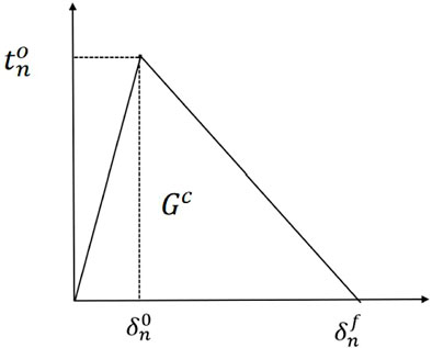
FIGURE 1. Typical traction—separation constitutive law.
According to Eq. 2, when the quadratic interaction function involving the contact stress ratio is equal to 1, damage occurs along the cohesive interface.
Where
The damage evolution of cohesion unit refers to the subsequent mechanical property degradation process after the initial damage of the unit. It is generally believed that cohesion unit has two evolution types, namely displacement damage evolution and energy damage evolution. Bilinear degradation mode in energy damage evolution is adopted in this paper. For energy-based damage evolution, the parameter describing the damage behavior of cohesion units is the fracture energy release rate. For bilinear degradation mode, the fracture energy release rate is defined as:
Where, Wc is the release rate of fracture energy of the element, the area enclosed by the stress-displacement curve, J/m2.
3 Finite element model building
3.1 Model establishment
Using Abaqus finite element software to establish the three-dimensional geometric model of cement plug formation interface as shown in Figure 2. Cement plug diameter 290 mm, overall 3D model size is 2 m × 2 m × 40 m.
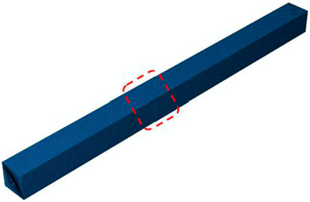
FIGURE 2. Overall finite element model grid diagram.
In order to simulate the failure condition of cement stop-formation interface, the numerical model established in this paper adopts the cohesive contact theory and takes the secondary nominal stress criterion as the criterion to judge the damage. In the model, it is assumed that the cement plug and stratum are elastic-plastic porous materials, and the elastic properties and bonding interface properties of the materials are shown in Table 1.
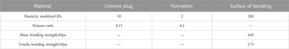
TABLE 1. Setting of model parameters.
If the bottom of the cement plug is poorly bonded to the formation, the cement plug—formation interface will appear micro-cracks, namely the existence of initial defects. A cohesive unit was inserted between the cement plug and the formation, and the initial break unit (the initial defect) was located at the bottom of the plug-casing interface. Structured grid and transition grid were used to discretize the model to improve the calculation accuracy (Figure 3).
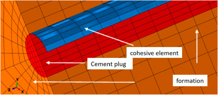
FIGURE 3. Grid diagram of the bottom of the finite element model.
Aiming at accurate calculation, a cohesive unit is inserted between the cement plug and formation interface, and a numerical damage model is established, which consists of three parts: the cement plug, the formation and the crack surface. The failure simulation of cement plug—formation interface bond under formation confining pressure and gas storage pressure is fully considered. The schematic diagram of the gas reservoir pressure on the cement plug-formation interface is shown in Figure 4.
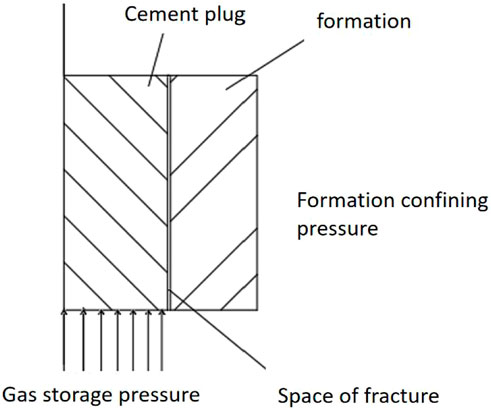
FIGURE 4. Schematic diagram of cement plug-formation interface subjected to gas storage pressure.
The model restricts the rotational degrees of freedom of the three surfaces of xyz, that is, the translational displacement of the three surfaces in the direction of the outer normal and the rotational displacement around the direction of the outer normal. The specific boundary condition settings are shown in Figure 5. In the whole simulation process, the ground stress of xyz surface is 23, 23 and 2.58 Mpa respectively, and the pressure at the bottom of the cement plug is constant 20 Mpa.
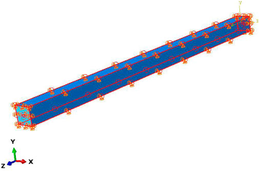
FIGURE 5. Boundary conditions of 3D finite element model.
3.2 Model verification
3.2.1 Bois model
Loizzo et al. (2015) described three basic requirements for an effective CMI simulator, namely: 1) the ability to evaluate the initial state of stress after cement sets; 2) The ability to estimate the position of cement design in the safe working envelope and the degree of approximation to the envelope limit; 3) The stiffness and failure behavior of all materials can be simulated to correctly locate the failure criterion limit. Bois et al. (2019) developed a model to simulate the mechanical and hydraulic integrity of a cement plug after cement setting, and simulated the micro-annulus generated by cement plug—formation interface stripping to understand how to prevent cement plug damage in the short and long term.
Modeling the cement plug-formation interface stripping process between 728 and 978 m in the vertical open hole shows that the most important risk of damage to the integrity of the cement plug is the creation of micro-annulus in the cement plug/wellbore view, and shows the geometry of the micro-annulus after hydration at the cement plug-wellbore interface. This study mainly focused on qualitative analysis, and did not specifically describe the interface stripping process, nor did it conduct a quantitative analysis of its influencing factors.
3.2.2 Bois model vs. finite element model
In this section, the parameters of Axel Pierre Bois et al.'s (2019) cement plug case study are selected, as shown in Table 2. Bois model and finite element model are respectively used to simulate the cement plug formation interface peeling process of 728–778 m open hole, and the change of micro ring size with depth is compared. In this case, the hole has a diameter of 0.216 m, and the formation has Young’s modulus and Poisson’s ratio values of 5 GPa and 0.20 respectively. The cement is a 1.95-g/cm3 API Class G cement system with Young’s modulus and Poisson’s ratio values of 10 GPa and 0.14. The applied WHP during the pressure test is 10 MPa.
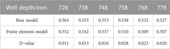
TABLE 2. Comparison between numerical model and Bois model to calculate micro-ring gap size.
As shown in Table 2, the maximum difference between the microannulus calculated by the finite element simulation and Bois model is 0.028 mm, and the maximum deviation is 5.12%, indicating that the established finite element model is basically reliable and can accurately simulate the cement stop-formation interface stripping.
3.3 Analysis of model results
According to the section milling hole size of a well in Jintan gas storage, Jiangsu Province, a 3D model of 290 mm × 40 m cement plug-formation system was established, and a cohesive unit was inserted to simulate the detachment failure of the cement plug-formation interface under constant pressure. The simulation results of the relative positions of the cement plug-formation interface after shear failure are shown in Figure 6.
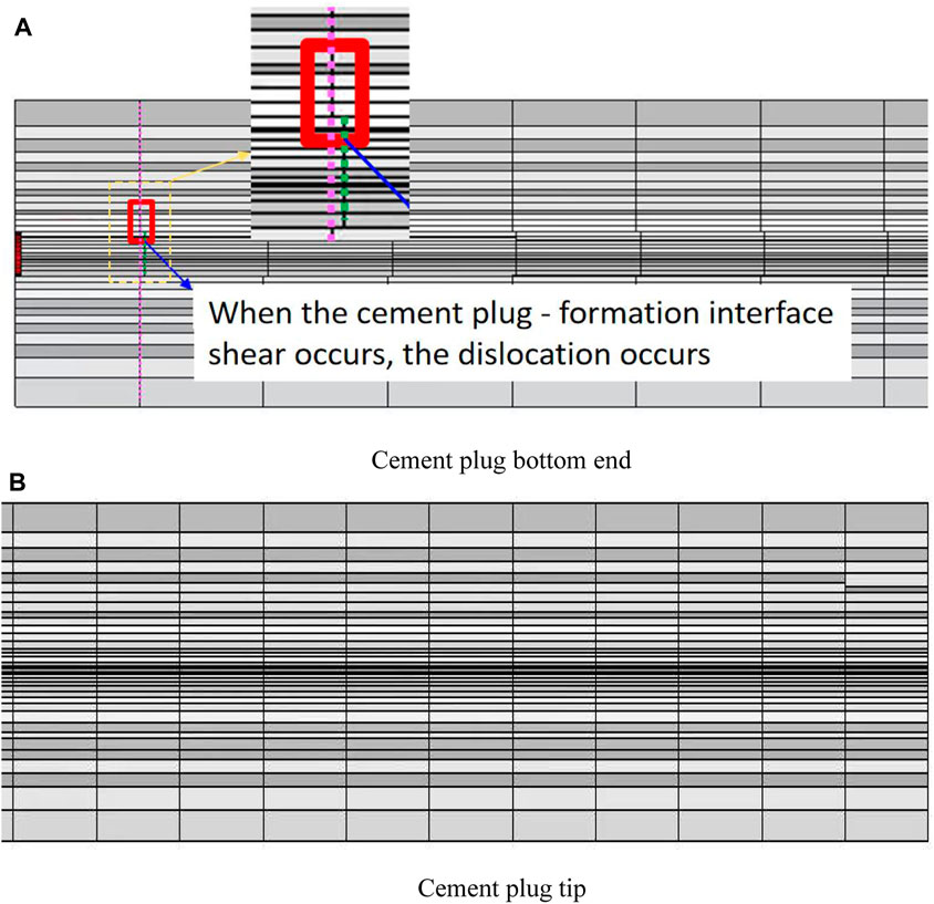
FIGURE 6. Schematic diagram of relative position after shear failure of cement plug-formation interface. (A) The simulation diagram of the relative position of the bottom of the cement plug after the shear failure of the cement plug-formation interface. (B) The simulation diagram of the relative position of the top of the cement plug after the shear failure of the cement plug-formation interface.
As shown in Figures 6A, the grid at the bottom of the cement plug is dislocated, which is because the cement plug is subjected to the gas storage pressure and causes cumulative deformation. With the increase of simulation time, the cement plug and the formation cementation surface will be sheared and dislocated along the borehole direction, resulting in the phenomenon of cement plug stripping. However, the stripping failure did not spread to the entire bonding surface (no longitudinal dislocation along the borehole occurred at the top of the cement plug in Figure 6B).
The length of cement stop-formation interface stripping failure over time is shown below.
As shown in Figure 7, according to the stiffness degradation coefficient SDEG of cement sheath interface, the failure of cement sheath interface is judged. When the cohesive damage parameter SDEG of the cement plug formation interface reaches 1, it indicates that the interface has been stripped at this time; 0 means no damage has occurred. The blue part represents the cement plug segment without stripping failure at the cement plug-formation interface, and the red part represents the cement plug segment with stripping failure. In the initial state (0 s), the cement plug did not undergo any deformation and was in a normal state without any peeling phenomenon. With the increase of the simulation time, the cement plug was subjected to the pressure of the gas reservoir at the bottom to produce a small deformation. When the simulation time reached 5 s, the cement plug was stripped, and the length of the red strip was 15.7 m. When the simulation time reached 22.5 s, the peel length of cement plug reaches 18.4 m, and when the simulation time reached 32.5 s, the peel length always stays at about 18.4 m, indicating that the ultimate peel length has been reached at this time.
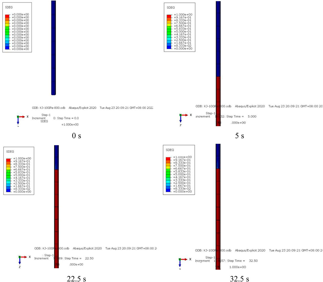
FIGURE 7. Stripping failure length vs. time.
In conclusion, under the constant pressure of 20 MPa, the cement plug—formation interface will have stripping failure, and there is a limit stripping failure length. When the cement plug is subjected to the bottom pressure, a certain degree of small deformation occurs, resulting in the shear direction deformation of the cement-plug interface. With the increase of simulation time, the length of the stripping segment gradually increased and tended to be stable, and the ultimate stripping failure length was 18.4 m. The model can determine the effective cementing length of cement plug for milling and plugging old wells in gas storage section. Effective cementation length is equal to section milling and plugging length (40 m) minus ultimate stripping length (18.4 m). Therefore, it is suggested that the length of cement plug in section milling should be greater than the ultimate stripping failure length, so as to ensure the safety and long-term effectiveness of plugging operation in the old wells.
4 Results and discussions
Since the 1960s, debonding of the cement/casing or cement/rock interface has been identified as a cause of wellbore leaks (Carter and Evans, 1964). The debonding of cementing-interface is mainly caused by the displacement difference between casing, cement ring and formation during perforation (Yan et al., 2020). This interface debonding may be caused by pressure and temperature changes and cement shrinkage during drilling operations (Lecampion et al., 2013). The degradation of cement strength has a significant influence on the occurrence of failure (debonding, radial crack, and disc) (Zhang et al., 2021). On the basis of previous researches, a 3D finite element model of the cement plug-formation system based on the cohesive element method is used in this chapter to analyze the factors affecting the stripping failure length of the cement plug-formation interface.
4.1 Failure law of stripping under dynamic pressure
Lecampion et al. (2013) investigated what controls the propagation of this interfacial fluid disbonding at constant pressure injection conditions below the formation fracturing pressure. The aim is understanding the effects of this fluid-driven micro-annulus debonding in a CO2 storage environment. This section mainly studies the peeling failure law of cement plug - formation interface under the dynamic change of the gas storage pressure.
The pressure of the gas storage tank will change dynamically during operation. As can be seen from Figures 8, 9, rapid stripping will occur at the cement stop-formation interface under higher pressure, and the stripping speed will slow down when the pressure decreases, and the stripping length will further increase when the pressure increases.
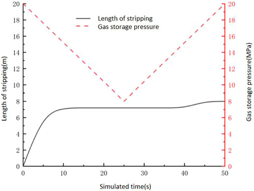
FIGURE 8. Stripping failure length vs. pressure.
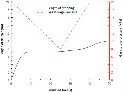
FIGURE 9. Stripping failure length vs. pressure.
By comparing Figures 7, 8, it can be seen that the peel failure length (8 m) under pressure is smaller than that under constant pressure (18.4 m).
In Figure 8, the gas storage pressure first decreases to 8 MPa with the simulation time, increases after 25 s, and gradually increases to 20 MPa. After the simulation time (50 s) is over, the stripping failure length is 8 m. In Figure 9, the gas storage pressure decreases to 8 MPa with the simulation time at first, then increases to 20 MPa gradually after 25 s, and then becomes stable after 40 s. After the simulation time (50 s) is over, the stripping failure length is 10 m. The failure length (10 m) under decrease-augment-stable condition is greater than that under decrease-augmentation condition (8 m).
The dynamic change mode of the gas storage pressure during operation can be optimized and adjusted according to the needs.
4.2 Stripping main control factors of failure
4.2.1 Operating pressure
As shown in Figure 10, no stripping occurred at the cement-stop-formation bonding interface when the gas reservoir pressure was low (8 MPa). When the pressure reached about 11 Mpa, the interface began to peel (0.8 m) and rapidly increased. When it increased to 20 MPa, the stripping failure length reached the limit value (18.4 m). The cement plug - formation interface did not peel and fail under lower pressure conditions because the gas reservoir pressure did not reach the failure strength of the bond surface.
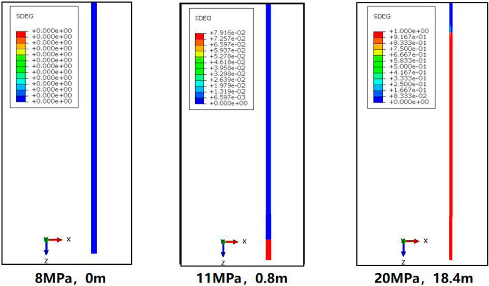
FIGURE 10. The stripping length varies with the gas storage pressure.
It can be clearly seen from Figure 11 that the stripping failure length increases with the increase of gas storage pressure.
FIGURE 11. The stripping length varies with the gas storage pressure.
It can be concluded that reducing the maximum operating pressure of gas storage is beneficial to ensure the safe and long-term operation of gas storage.
4.2.2 Length of cement plug
As can be seen from Figure 12, under the same gas storage pressure, complete stripping will occur at the end of simulation when the length of cement plug is 10 and 20 m. When the cement plug length is 30 m, the stripping failure length is 21.4 m. When the cement plug length is 40 m, the stripping failure length is 18.4 m. When the length of cement plug is 50 m, the stripping failure length is 17 m. The change curve of the peeling failure length of the cement plug-formation interface with the length of the cement plug is shown in Figure 13.
FIGURE 12. The stripping length varies with the length of the cement plug.
FIGURE 13. Line diagram of strip length changing with cement plug length.
In summary, the peel length of cement stop-formation interface decreases with the increase of cement stopper length, because the longer the cement stopper length is, the larger the equivalent cementing area is, and the smaller the peel failure length is under the same gas storage pressure. Therefore, the length of cement plug should not be too short during the section milling operation. According to different underground engineering geological conditions, it is suggested to optimize the length of section milling plugging operation, reduce the engineering operation cost as much as possible and shorten the construction cycle of gas storage.
4.2.3 Diameter of cement plug
As can be seen from Figure 14, when the diameter of cement plug is 118.6 mm, the cement plug does not peel. When the diameter of the cement plug is 157.1 mm, the stripping starts to occur and the stripping length of the cement plug is 8 m. When the cement plug diameter is 220.5 mm, the cement plug stripping length increases to 12 m. When the diameter of cement plug is 290 mm, the stripping length of cement plug reaches the ultimate stripping length of 18.4 m.
FIGURE 14. The strip length varies with the cement plug diameter.
In conclusion, the peel length of cement stop-formation bond interface will increase with the increase of cement plug diameter. This is because the larger the diameter of cement plug is, the greater the equivalent thrust acting on the bottom of cement plug under the same gas storage pressure, resulting in the increase of the peel length. Therefore, when the hole size is small, the length of the section milling plug can be reduced appropriately.
4.2.4 Elastic modulus, Poisson’s ratio
Boukhelifa et al. (2004) conducted large-scale annulus seal tests that showed that cement mechanical properties (such as elasticity, strength, and expansion) and rock properties were key parameters for maintaining the integrity of the cement ring over the life of the well. However, the relationship between specific properties (such as elastic modulus, Poisson’s ratio) and the length of cement plug stripping failure was not simulated. Therefore, this section mainly focuses on the influence of elastic modulus and Poisson’s ratio of cement plug on stripping failure length.
As can be seen from Figure 15, with the increase of elastic modulus of cement plug, the peel failure length of cement plug-casing interface gradually decreases. When the elastic modulus increases from 6 GPa to 14 GPa, the stripping failure length decreases from 39.4 m to 2.4 m, which indicates that the elastic modulus of cement plug has a great influence on the crack stripping failure of cement plug-casing interface. This is because with the increase of elastic modulus, the deformation of cement plug becomes smaller, leading to the decrease of cumulative fracture energy. As a result, the use of a higher elastic modulus cement plug in well abandonment operations can improve the integrity of the cement-casing interface.
FIGURE 15. Influence of elastic modulus of cement plug on stripping length.
As can be seen from Figure 16, with the increase of cement Poisson’s ratio, the peel failure length of cement plug-casing interface gradually decreases. When Poisson’s ratio increases from 0.1 to 0.3, the stripping failure length decreases from 19.8 to 14.2 m, indicating that the cement plug Poisson’s ratio has an effect on the cement-casing interface, but the effect is not as obvious as the elastic modulus of cement plug. The separation failure length of cement plug-casing interface will change with the change of Poisson’s ratio, because the increase of Poisson’s ratio will increase the transverse deformation of cement plug and lead to the increase of slip friction. As a result, high Poisson’s ratio is more friendly to seal integrity at the cement stop-casing interface.

FIGURE 16. Influence of cement Poisson’s ratio on the length of stripping.
5 Conclusion
A total of 25 sets of simulation studies on cement stop-formation interface stripping failure under different cement plug lengths, diameters, gas storage pressure, pressure change modes and cement plug performance were carried out. The interface stripping failure rule under constant/dynamic pressure conditions was defined, the influence rule of different factors on stripping failure length was revealed, and the calculation method of effective cement plug bonding length for milling and plugging old wells in gas storage section was determined. Some meaningful conclusions are presented as follows.
(1) A 3D finite element model of the cement plug-formation system based on Cohesive element method in this research can accurately simulate the cement plug-formation interface bonding failure process, which is helpful to judge whether the milling and plugging length of the old well section is sufficient, and provide theoretical guidance for ensuring the long-term and safe operation of gas storage.
(2) Under the condition of constant pressure in gas storage tank, the bottom of cement plug will undergo a certain degree of minor deformation after compression, resulting in shear deformation of cement-stopper cement-formation bond interface. When accumulated to a certain degree, the cement-stopper cement-formation bond interface will be stripped. The stripping failure length increases gradually with time, and finally tends to be stable, reaching the ultimate stripping failure length.
(3) The ultimate peel length under dynamic pressure is smaller than that under constant pressure, and the peel length under “decrease-augmentation—stabilization” is larger than that under “decrease-augmentation.”
(4) The operating pressure, cement plug length, cement plug diameter, elastic modulus of cement plug, Poisson’s ratio and other factors of gas storage will also affect the stripping length of cement plug formation cementation interface. Therefore, it is recommended to use a cement slurry system with high elastic modulus and high Poisson’s ratio, appropriately reduce the length of forging and milling plugging, reduce the maximum operating pressure of the gas storage, and optimize and adjust the dynamic change mode of the gas storage pressure during operation to reduce the length of interface failure and ensure the safe and long-term operation of the gas storage.
Data availability statement
The original contributions presented in the study are included in the article/supplementary material, further inquiries can be directed to the corresponding author.
Author contributions
JW: Conceptualization, Methodology, Writing—Review and Editing. CC: Software, Writing—Original Draft. PF: Resources, Formal analysis, Data Curation. SD: Project administration, Supervision. ZT: Investigation, Validation.
Funding
This research is supported by the Project of China National Petroleum Corporation (CNPC) (2021DJ5402), the Research Foundation of Changzhou University (ZMF22020060), and the Basic Science (Natural Science) Research Project of Jiangsu Higher Education (22KJD430001).
Conflict of interest
Author PF was employed by CNPC Research Institute of Engineering Technology Co., Ltd.
The remaining authors declare that the research was conducted in the absence of any commercial or financial relationships that could be construed as a potential conflict of interest.
Publisher’s note
All claims expressed in this article are solely those of the authors and do not necessarily represent those of their affiliated organizations, or those of the publisher, the editors and the reviewers. Any product that may be evaluated in this article, or claim that may be made by its manufacturer, is not guaranteed or endorsed by the publisher.
References
Akgün, H., and Daemen, J. J. (1999). Design implications of analytical and laboratory studies of permanent abandonment plugs. Can. Geotechnical J. 36 (1), 21–38. doi:10.1139/t98-089
Asala, H. I., and Gupta, I. (2019). “Numerical modeling aspects of fluid-driven interface debonding after wellbore plugging and abandonment,” in 53rd US rock mechanics/geomechanics symposium (OnePetro). New York, NY, USA.
Bai, S., Ding, G., Wanyan, Q., Li, K., and Li, H. (2022). “Feasibility study on transformation of abandoned salt caverns into underground gas storage in China,” in 56th US rock mechanics/geomechanics symposium (OnePetro). Santa Fe, New Mexico, USA.
Benge, G. (2009). Improving wellbore seal integrity in CO2 injection wells. Energy Procedia 1 (1), 3523–3529. doi:10.2118/119267-MS
Bérest, P., and Brouard, B. (2003). Safety of salt caverns used for underground storage blow out; mechanical instability; seepage; cavern abandonment. Oil Gas Sci. Technol. 58 (3), 361–384.
Bois, A. P., Vu, M. H., Noël, K., Badalamenti, A., Delabroy, L., Therond, E., et al. (2019). Evaluating cement-plug mechanical and hydraulic integrity. SPE Drill. Complet. 34 (02), 92–102. doi:10.2118/191335-PA
Bosma, M., Ravi, K., van Driel, W., and Schreppers, G. J. (1999). “Design approach to sealant selection for the life of the well. Society of Petroleum Engineers,” in Presented at the SPE annual technical conference and exhibition OnePetro (Houston, TX, USA: October 1999), 3–6. doi:10.2118/56536-MS
Boukhelifa, L., Moroni, N., James, S. G., Roy-Delage, L., Thiercelin, M. J., and Lemaire, G. (2004). “Evaluation of cement systems for oil and gas well zonal isolation in a full-scale annular geometry,” in IADC/SPE drilling conference (OnePetro). Dallas, TX, USA. March, 2004. doi:10.2118/87195-MS
Carter, L. G., and Evans, G. W. (1964). A study of cement-pipe bonding. J. Petroleum Technol. 16 (02), 157–160. doi:10.2118/764-PA
Cornet, J. S., Dabrowski, M., and Schmid, D. W. (2018). Long term creep closure of salt cavities. Int. J. Rock Mech. Min. Sci. 103, 96–106. doi:10.1016/j.ijrmms.2018.01.025
De Simone, M., Pereira, F. L., and Roehl, D. M. (2017). Analytical methodology for wellbore integrity assessment considering casing-cementformation interaction. Int. J. Rock Mech. Min. Sci. 94, 112–122. doi:10.1016/j.ijrmms.2016.12.002
Dian, W., Jun, L., Xianbo, L., Tuo, L., Penglin, L., and Wei, L. (2022). Analysis of cement plug bonding surface integrity in CO2 geological storage. In 56th US rock mechanics/geomechanics symposium. OnePetro. doi:10.56952/ARMA-2022-0213
Dong, J., Li, G., Liu, T., Li, J., and Zhang, Y. (2021). “Stability analysis of underground-gas-storage salt cavern based on similarity criterion,” in 55th US rock mechanics/geomechanics symposium (OnePetro). Richardson, TX, USA.
Feng, Y., Li, X., and Gray, K. E. (2017). Development of a 3D numerical model for quantifying fluid-driven interface debonding of an injector well. Int. J. Greenh. Gas Control 62, 76–90. doi:10.1016/j.ijggc.2017.04.008
Fleckenstein, W. W., Eustes, A. W., and Miller, M. G. (2001). Burst-induced stresses in cemented wellbores. SPE Drill. Complet. 16, 74–82. doi:10.2118/72059-PA
Fourmaintraux, D. M., Bois, A. P., and Fraboulet, B. (2005). “Efficient wellbore cement sheath design using the SRC (System Response Curve) method,” in SPE europec/EAGE annual conference (OnePetro). Madrid, Spain, June 2005. doi:10.2118/94176-ms
Gray, K. E., Podnos, E., and Becker, E. (2009). Finite-element studies of near-wellbore region during cementing operations: Part I. SPE Drill. Complet. 24 (01), 127–136. doi:10.2118/106998-PA
He, H., and Arson, C. (2022). “Numerical implementation of a cohesive zone element coupled with continuum damage mechanics volume elements,” in 56th US rock mechanics/geomechanics symposium. OnePetro. Richardson, TX, USA. doi:10.56952/ARMA-2022-0324
Jing, W. J., Yang, C. H., and Chen, F. (2011). Risk assessment of salt cavern oil/gas storage based on accident statistical analysis. Rock Soil Mech. 32 (6), 1787–1793. doi:10.1631/jzus.B1000185
Kiran, R., Teodoriu, C., Dadmohammadi, Y., Nygaard, R., Wood, D., Mokhtari, M., et al. (2017). Identification and evaluation of well integrity and causes of failure of well integrity barriers (a review). J. Nat. Gas. Sci. Eng. 45, 511–526. doi:10.1016/j.jngse.2017.05.009
Lecampion, B., Bunger, A., Kear, J., and Quesada, D. (2013). Interface debonding driven by fluid injection in a cased and cemented wellbore: Modeling and experiments. Int. J. Greenh. Gas. Control. 18, 208–223. doi:10.1016/j.ijggc.2013.07.012
Loizzo, M., Bois, A. P., Etcheverry, P., and Lunn, M. G. (2015). An evidence-based approach to well-integrity risk management. SPE Econ. Manag. 7 (03), 100–111. doi:10.2118/170867-PA
Lu, Y. H., Wei, S. M., Xia, Y., and Jin, Y. (2020). Modeling of geomechanics and fluid flow in fractured shale reservoirs with deformable multi-continuum matrix. J. Petroleum Sci. Eng. 196, 107576. doi:10.1016/j.petrol.2020.107576
Pamucar, D., Deveci, M., Schitea, D., Eriskin, L., Iordache, M., and Iordache, I. (2020). Developing a novel fuzzy neutrosophic numbers based decision making analysis for prioritizing the energy storage technologies. Int. J. Hydrog. Energy. 45 (43), 23027–23047. doi:10.1016/j.ijhydene.2020.06.016
Pinto, J. S. R., Bachaud, P., Fargetton, T., Ferrando, N., Jeannin, L., and Louvet, F. (2021). Modeling phase equilibrium of hydrogen and natural gas in brines: Application to storage in salt caverns. Int. J. Hydrogen Energy 46 (5), 4229–4240. doi:10.1016/j.ijhydene.2020.10.242
Qiu, K. X., and Li, H. (2018). A new analytical solution of the triple-porosity model for history matching and performance forecasting in unconventional oil reservoirs. SPE J. 23, 2060–2079. doi:10.2118/191361-PA
Shi, X. L., Yang, C. H., Li, Y. P., Li, J. L., Ma, H. L., Wang, T. T., et al. (2017). “Development prospect of salt cavern gas storage and new research progress of salt cavern leaching in China,” in 51st US rock mechanics/geomechanics symposium (OnePetro). San Francisco, CA, USA.
Sovacool, B. K. (1907–20072008). The costs of failure: A preliminary assessment of major energy accidents. Energy Policy 36 (5), 1802–1820. doi:10.1016/j.enpol.2008.01.040
Wang, W., and Taleghani, A. D. (2014). Three-dimensional analysis of cement sheath integrity around Wellbores. J. Petroleum Sci. Eng. 121, 38–51. doi:10.1016/j.petrol.2014.05.024
Yan, Y., Guan, Z., Xu, Y., Yan, W., and Chen, W. (2020). Study on debonding issue of cementing interfaces caused by perforation with numerical simulation and experimental measures. SPE Drill. Complet. 35 (04), 684–695. doi:10.2118/201208-PA
Yao, Y., Gosavi, S. V., Searles, K. H., and Ellison, T. K. (2010). “Cohesive fracture mechanics based analysis to model ductile rock fracture,” in 44th US rock mechanics symposium and 5th US-Canada rock mechanics symposium (OnePetro). Salt Lake City, Utah.
Keywords: salt cavern gas storage, stripping failure length, cohesive element method, integrity of seal, cement plug-formation interface
Citation: Wang J, Cai C, Fu P, Deng S and Tang Z (2023) Study on simulation of cement plug—formation interface stripping failure and main influencing factors. Front. Earth Sci. 11:1123620. doi: 10.3389/feart.2023.1123620
Received: 14 December 2022; Accepted: 09 January 2023;
Published: 20 January 2023.
Edited by:
Shiming Wei, China University of Petroleum, Beijing, ChinaReviewed by:
Kaixuan Qiu, Jiangmen Laboratory of Carbon Science and Technology, ChinaCan Shi, China University of Petroleum, China
Copyright © 2023 Wang, Cai, Fu, Deng and Tang. This is an open-access article distributed under the terms of the Creative Commons Attribution License (CC BY). The use, distribution or reproduction in other forums is permitted, provided the original author(s) and the copyright owner(s) are credited and that the original publication in this journal is cited, in accordance with accepted academic practice. No use, distribution or reproduction is permitted which does not comply with these terms.
*Correspondence: Chuchu Cai, ODQyNjk3OTc5QHFxLmNvbQ==