 Li Hongru
 Yang Min
 Li Jiaqi
- 1Institute of Geotechnical Engineering, Xi’an University of Technology, Xi’an, China
- 2Loess Soil Mechanics and Engineering Key Laboratory of Shaanxi Province, Xi’an, China
During construction of concrete faced rockfill dam (CFRD), the extrusion-sidewall will be protruding or deficiency under normal. Before panel construction, local slope cutting should be taken for the squeezed side wall or supplementary filling measures should be taken after excavating the squeezed side wall, which will affect the mechanical deformation of the panel. According to the monitoring data of concrete-faced rockfill dams of some hydro-electric station in Hubei Province, the three-dimensional finite element analysis method is used to simulate the original filling sequence process of the concrete face rockfill dam. By comparing the difference between the monitoring data and the calculation results, the deformation law of the extrusion side wall and the dam is obtained, which verifies the rationality of the three-dimensional simulation analysis of the dam. The characteristic values of settlement and horizontal displacement obtained from dam monitoring and numerical calculation are compared with those of other high concrete faced rockfill dams. The characteristic values of this dam are close to those of general concrete faced rockfill dams. The deformation law of extrusion side wall and dam under two optimization schemes with different filling sequence is studied. It is found that if conditions permit, the upstream should be filled first and then the downstream to reduce the deformation of extrusion side wall to the upstream.
1 Introduction
The construction technology of extruding side wall (abbreviated as extruded-sidewall) is a new construction method of concrete faced rockfill dam (CFRD), which especially reduces the over-filling repair process of cushion material, reduces labor intensity and saves labor. No need for traditional construction techniques in slope leveling, slope rolling, sand blasting slurry to stabilize slope. Because of the advantages of improving the rolling quality of cushion materials, speeding up the construction progress, and protecting the surface of cushion materials from rain erosion during construction, this technology has been adopted in high face rockfill dam projects such as Shuibuya, Gongbo Gorge, Jishi Gorge, and Bakun, Malaysia (Jiang 1997; Galvao et al., 1999; Li 2011). Although the construction of the extrusion-sidewall has many advantages and has been widely used (Luo et al., 2005), the application of the extrusion-sidewall in the panel dam is still very short, and people are not very clear about many aspects of its problems. For example, because the elastic modulus of the side wall material is much larger than that of the rockfill material, a certain degree of stress concentration may occur on the extrusion-sidewall. The sidewall concrete is different from the conventional concrete and rockfill. It is a special structural material with rapid setting, low elastic modulus, and plastic damage. As a semi-elastic layer sandwiched between the concrete panel and the rockfill, how about its stress and strain, which is not clear at present. At the same time, since the extrusion-sidewall is constructed layer by layer along the dam axis, there will be more or less staggered layers. From the perspective of contact friction, the staggered layers of the upper and lower extrusion-sidewalls will increase the deformation of the extrusion-sidewall towards the upstream, and also increase the constraint effect on the panel (Peng et al., 2008; Zhou et al., 2008). In the past, the first thing people pay attention to is the stress deformation and stability of the CFRD (Sun et al., 2006; Deng et al., 2008; Liu et al., 2010; Li and Yang. 2012; Liu and Liu. 2013; Yang et al., 2014; Zhang et al., 2022), followed by the contact between the face slab and the extrusion-sidewall (Zhang et al., 2005; Hou et al., 2008; Zou et al., 2009) and the stress and strain of the concrete face slab (Cheng et al., 2011; Deng et al., 2015; Zhou et al., 2015; Liu et al., 2022), and little attention is paid to the factors affecting the extrusion-sidewall and the deformation law (Pan et al., 2014; Hu et al., 2016).
The extrusion-sidewall is constructed at the same time with the dam. Due to the influence of dam deformation and the discontinuity between layers caused by the layered construction of the extrusion-sidewall, many concrete faced rockfill dams have to cut and fill the extrusion-sidewall before the construction of the dam is completed and the panel is not constructed, resulting in a large difference between the actual size of the extrusion-sidewall and the design size, which affects the stress and deformation of the panel. In order to reduce the cutting and filling of the extrusion-sidewall, it is generally necessary to reserve a certain amount of space for extruding sidewall to deform upstream during dam construction to meet the design requirements of the extrusion-sidewall. In the case of the dam type and filler are determined, it is worth paying attention to the study of the influence of the construction sequence on the deformation of the layered discontinuous extrusion-sidewall.
This paper strictly simulates the actual construction process through the FEM calculation method based on the actual construction of the CFRD of a hydropower station in Hubei Province. It compares the horizontal displacement and settlement deformation monitored during the actual filling process of the dam with the numerical simulation results, which verifies the scientific nature of the numerical simulation method, the rationality of material parameter selection, and the correctness of the results. On this basis, the deformation law of the extrusion side wall of the CFRD of the hydropower station under different construction schemes is studied, which provides a reference for the construction scheme design of the same type of dam.
2 Project overview
The dam of a hydropower station in Hubei is a reinforced the CFRD. The length of the dam crest axis is 465.00 m, the width of the dam crest is 10 m, the elevation of the dam crest is 524.30 m, the foundation surface elevation of the riverbed toe slab is 366.00 m, and the maximum dam height is 158.3 m. The upstream slope ratio of the dam is 1:1.4, and the downstream comprehensive slope ratio is 1:1.44. The thickness of the upper part of the reinforced concrete panel is 30 cm, and the thickness of the bottom is 84 cm. The dam is divided into primary and secondary rockfill areas, and the downstream dam toe is equipped with a filter rockfill prism. The dam under construction is shown in Figure 1, and the material partition is shown in Figure 2.

FIGURE 1. The construction of concrete face rockfill dam.
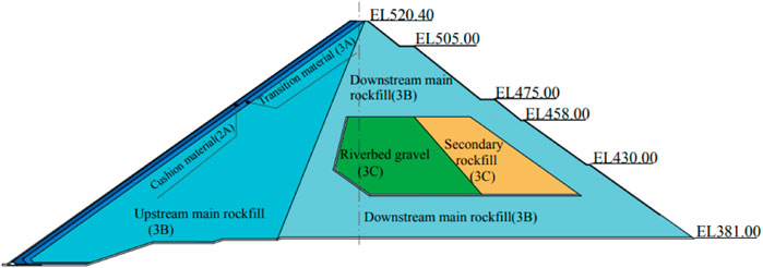
FIGURE 2. Dam material partition drawing.
The total filling amount of the dam is about 7 million m3, of which more than 600,000 m3 is weakly weathered sand shale excavated from the spillway, and 400,000 m3 is natural gravel of riverbed sand field. The rock material for constructing dam in the main rockfill area is mainly gray thick strip limestone and gray thick dolomite.
3 Deformation monitoring of dam and extrusion-sidewall during construction
In order to evaluate the construction quality, the deformation of the concrete face rockfill dam during the construction period is monitored to prevent accidents such as uncompacted rolling or excessive deformation of the dam. According to the characteristics of concrete face rockfill dam, a comprehensive safety monitoring system is set up to carry out real-time monitoring according to the requirements of relevant regulations and specifications during construction. Figure 3 shows that the sequence and time of dam filling.
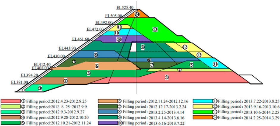
FIGURE 3. Dam filling sequence diagram.
3.1 Monitoring instrument layout scheme
In order to obtain the deformation of the dam and the extrusion-sidewall during the construction period, deformation measuring instruments are specially set at the section of the riverbed centerline perpendicular to the dam and the extrusion side wall. The vertical displacement is measured by water tube type settlement meter in Figure 4. The horizontal displacement is measured by tension wire type horizontal displacement meter in Figure 5.
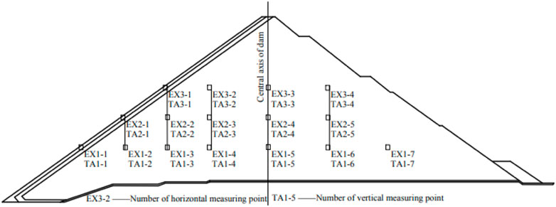
FIGURE 4. Layout of deformation monitoring instrument at riverbed cross section.
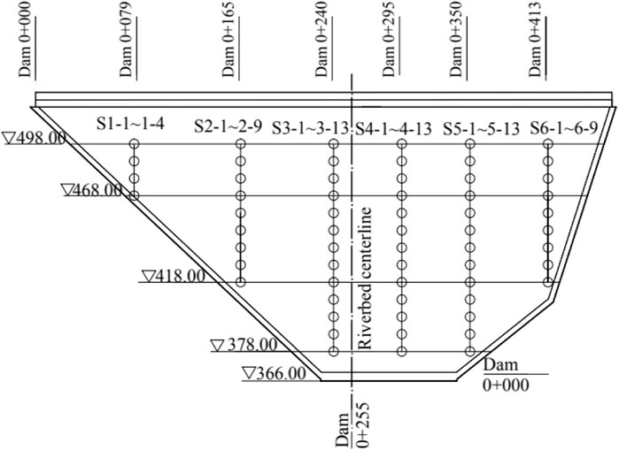
FIGURE 5. Layout of squeezed sidewall deformation monitoring instrument.
3.2 Arrangement and analysis of monitoring data
When the dam was completed in March 2014, the maximum upstream deformation at the dam elevation of 412.00 was 33.0 cm, and the deformation at the downstream measuring point was 32.5 cm. At the dam elevations of 437.00 and 462.00, the upstream horizontal displacement decreases slightly and the downstream horizontal displacement increases slightly, as shown in Figure 6. The vertical displacement occurs at the elevation of 437.00, with the maximum value of 134.1 cm. It is located near the upper of one-third of the dam height, and the settlement decreases gradually along the dam towards the upstream and downstream areas, as shown in Figure 7. The maximum position of horizontal and vertical deformation is not at the same height, but it conforms to the general deformation law of dam.
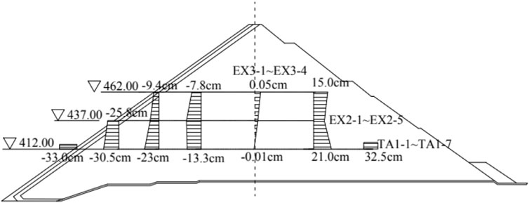
FIGURE 6. Horizontal deformation of dam In March 2014.
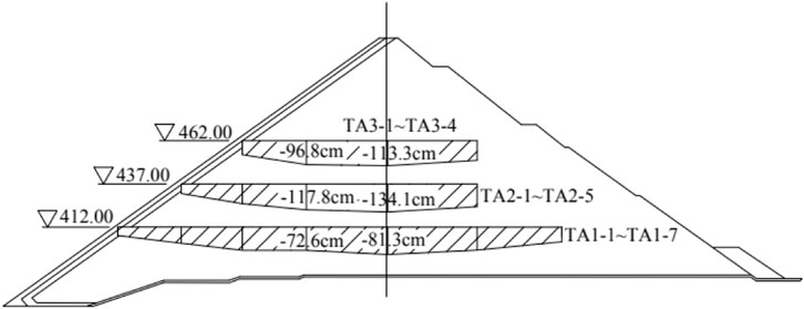
FIGURE 7. Vertical deformation of dam In March 2014.
The deformation of the extruded side wall along the river occurs at the dam height of 418 m, and the maximum deformation upstream is 33.4 cm, which occurs on the left side of the dam, 40 m from the centerline of the riverbed, and is one-third of the dam height. As the right side of dam abutment is steeper than the left side, the upstream displacement along the river on the left side of the dam is smaller than the right side, and the displacement near the dam abutment on both sides is reduced, which is mainly restricted by the dam abutment on both sides, as shown in Figure 8. The maximum vertical displacement of the extrusion-sidewall is 34.7 cm, which occurs at the dam height of 450 m, and is near two-thirds of the dam height. It occurs on the left side of the dam and is 40 m away from the riverbed centerline in Figure 9. Although the maximum horizontal displacement and vertical displacement do not occur at the same dam height, they are consistent with the laws of horizontal and vertical deformation of the dam.
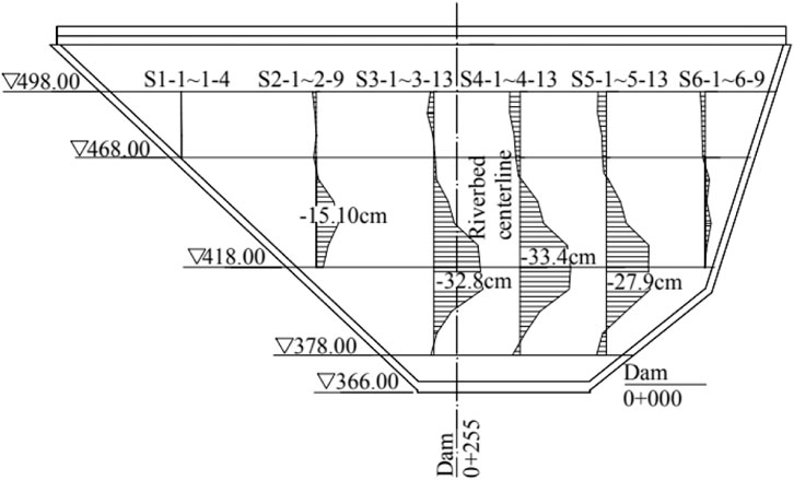
FIGURE 8. Displacement of wall extrusion along the river in March 2014.
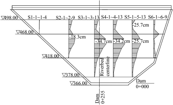
FIGURE 9. Vertical displacement of extrusion-sidewall in March 2014.
4 Numerical simulation method
4.1 Calculation principle
The midpoint increment method is used in this calculation. For the first load increment
4.2 Computational model
Three-dimensional solid modeling and finite element meshing are carried out according to dam material partition and filling scheme, as shown in Figure 10. The rockfill, dam and foundation are modeled mainly by three-dimensional eight-node hexahedron element. It is proposed that four-node quadrilateral element are used in the local areas. The number of elements is 18,920 and the number of nodes is 21,241. The boundary is constrained by displacement, and the left and right sides and bottom of the dam are fully constrained. For the treatment of extrusion-sidewall, refer to the method in reference (Zhang et al., 2005), and the extrusion-sidewall is equivalent to a whole concrete continuous thin plate, with the thickness of the side wall equivalent to 24 cm. A thin layer unit is set between the extrusion-sidewall and the cushion material as the equivalent contact surface (Popp et al., 2010). The thickness of the thin layer unit is 10 cm, and its modulus is the modulus of the cushion.
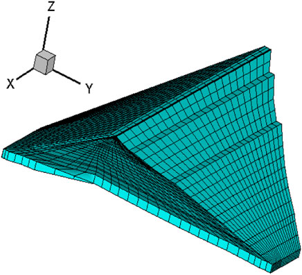
FIGURE 10. FEM mesh of the dam.
4.3 Material constitutive model and parameters
Linear elastic constitutive model is adopted for extrusion-sidewall in this calculation. The elastoplastic “Nanshui” constitutive model is adopted for rockfill, because the elastic-plastic model can well reflect the shear shrinkage of rockfill (Luo and Xiu-run. 2008). Calculation model parameters are shown in Table 1.
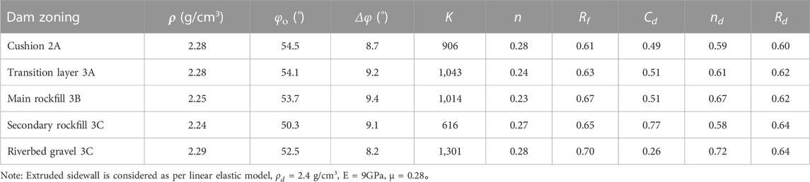
TABLE 1. The Nanshui model’s parameters of the dam’s material.
4.4 Load and application method
During the construction period of the dam, the load is the weight of the rockfill, and there is no water in the upstream and downstream of the dam. The simulated construction process is to calculate the stress-strain process of the squeezed side wall from the foundation to the dam crest elevation during construction. The load is applied to a total of 14 levels. The extrusion side wall is constructed from the third level of the dam when it is filled with the dam, as shown in Figure 3.
4.5 Comparison and analysis of calculation results and monitoring data
According to the calculation, the maximum displacement of dam settlement on the section of riverbed centerline during the completion period is 1.2 m. Compared with the monitoring results, the location is similar, and the value is smaller than the monitoring value, with a difference of 0.14 m. At the same time, the three-dimensional calculation results show that due to the asymmetric “V” shape of the river valley, the dam settlement has obvious arch effect, and two large deformation and settlement areas are formed along the dam height, as shown in Figure 11. However, due to the limitation of the layout scope of monitoring instruments, this feature was not found in the monitoring results. Compared with the displacement and deformation in the horizontal direction of the dam, Figure 12 shows that the range of the horizontal displacement in the vertical direction along the river of the upstream face of the dam is basically close to the monitoring results, and the range of the downstream displacement along the river greater than 0.42 m is relatively small, which is in the shape of a long strip close to the slope. Compared with the monitoring results, the calculated values at the same location are smaller. Due to the limitation of the layout of monitoring points, the monitoring values cannot reflect the overall horizontal displacement of the downstream dam.

FIGURE 11. Settlement of the section of the river center line in Completion period (unit: m).
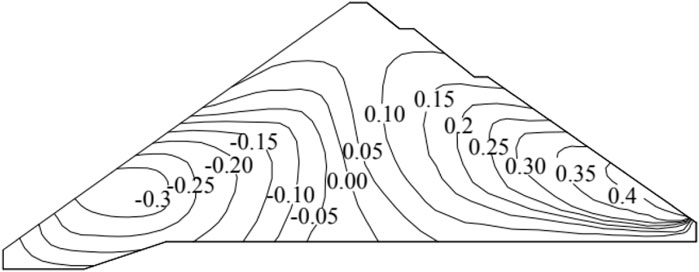
FIGURE 12. Horizontal deformation of the section of river center line in Completion period (unit: m).
Comparing the calculated and monitored horizontal displacement and deformation of the extrusion-sidewall along the river, it is found that the calculated value of 30 cm is less than the monitored value of 34.7 cm, and the range of calculated displacement of more than 30 cm is also less than the monitored value of more than 30 cm. However, the results of calculation and monitoring are in good agreement with each other. The maximum horizontal displacement occurs slightly less than one-half of the dam height, and deformation towards the downstream of the river occurs at the top of the dam, as shown in Figure 13. Figure 14 shows that it reflects the calculated vertical displacement diagram of the extrusion-sidewall during the completion period of the dam. The maximum calculated value is 28 cm, which is 6.7 cm smaller than the monitored vertical displacement 34.7 of the side wall. However, the maximum vertical displacement is located at two-thirds of the dam height, which is similar to the monitoring data and has the same rule, and also conforms to the general rule of the deformation of the extrusion-sidewall.
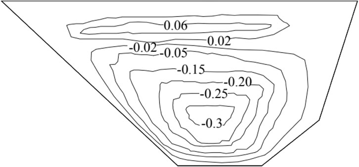
FIGURE 13. Horizontal deformation of the extruding side-wall in Completion period (unit: m).
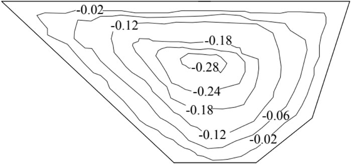
FIGURE 14. Vertical deformation of the extruding side-wall in Completion period (unit: m).
Comparing the monitoring and calculation results, the deformation laws of the two are the same. The calculated data is less than the monitoring data, and the error is about 10%. It shows that the numerical calculation method is more scientific and reasonable, which can better reflect the deformation law of the dam and the extruded side wall.
It is appropriate to use the settlement characteristic value
Where
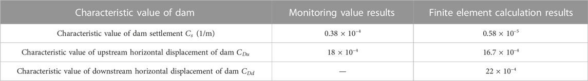
TABLE 2. Settlement and horizontal displacement’s characteristic value of numerical calculation and monitoring.
The
5 Influence of filling sequence on deformation of extrusion-sidewall and dam
5.1 Optimization of dam filling sequence
The extrusion-sidewall is generally trapezoidal, the upper thickness is generally 10 cm, and the lower thickness is about 70 cm. After the completion of dam filling, the extrusion-sidewall may have some slope loss or surplus. In order to lay the panel to reach the design coordinates, the method of partial slope cutting or filling after excavating the extrusion-sidewall is generally adopted. The other method is to predict the possible settlement and horizontal displacement of the extrusion-sidewall at a certain elevation of the dam surface through certain calculation and analysis, leaving a certain space for compensation during the dam filling process. On the basis of verifying the correctness of the numerical simulation method, this paper optimizes and selects two kinds of dam filling sequence schemes are shown in Figures 15, 16. In order to minimize the upstream deformation of dam, influence of the filling sequence on the horizontal displacement and settlement deformation of the extrusion-sidewall is studied. The correlation between the horizontal displacement of the extrusion side wall and the settlement deformation of the dam is compared and analyzed, and the dam filling sequence to reduce the deformation of the extrusion side wall is analyzed.
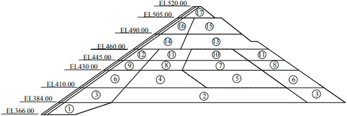
FIGURE 15. Plan Ⅰ of optimize the filling sequence.
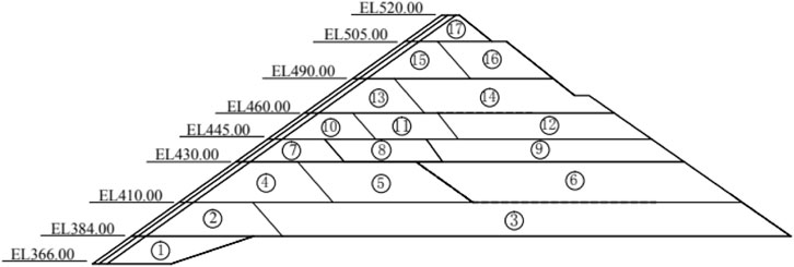
FIGURE 16. Plan Ⅱ of optimize the filling sequence.
5.2 Analysis of calculation results of optimization scheme
The deformation of the dam is mainly caused by the weight of the rockfill. When filling by stages, the deformation sequence of the upstream and downstream sections of the dam is different. Analyzing the upstream displacement along the river of the extrusion-sidewall after changing the filling sequence of the dam, it is found that the downstream first small block filling in the optimized schemeⅠreduces the horizontal displacement along the river to the upstream compared with the original actual large block filling, and the maximum value decreases by 4.2 cm. The position where the maximum value occurs rises slightly, the area decreases, and the deformation is gentle. At the same time, the deformation from the dam top to the downstream also decreases. When the upstream is filled first and the downstream is filled later, the upstream section has been filled and tends to be stable, and the later filling has little impact on its deformation, while the newly filled dam has large deformation, so the optimization scheme Ⅱ of the upstream early filling is better. As the filling is divided into small blocks, the deformation of the extrusion-sidewall towards the upstream decreases by 6.8 cm compared with the actual filling, and the maximum deformation is −26.6 cm, as shown in Figure 17.
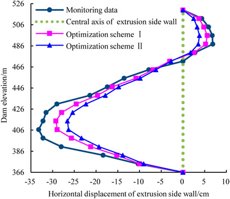
FIGURE 17. Displacement of Squeezing sidewall along the elevation along the river.
In order to compare the deformation of the side wall and dam under different filling schemes better and more intuitively, the calculation results are summarized as follows. From Table 3, it can be clearly seen that the maximum deformation of the side wall under the two filling schemes and the change rate between the monitoring value of the original filling scheme and the optimized scheme Ⅱ.
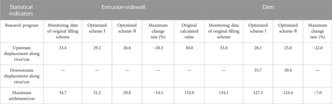
TABLE 3. Compare results of different filling the order.
It is reflected that when the optimum scheme Ⅱ is used for stage filling, the upstream section is filled first, then the downstream section in Table 3. The downstream section filling causes a small increment of settlement and horizontal displacement of the filled part of the dam. The final settlement and horizontal displacement of the dam are mainly affected by the upstream section filling body and the lower filling body. In scheme Ⅱ, the displacement of the extrusion-sidewall along the river to the upstream is reduced by 20.3%, the maximum settlement is reduced by 14.1%, the displacement of the dam to the upstream is reduced by 22%, and the maximum settlement is reduced by 7%. It also reflects that the filling sequence has more influence on the horizontal displacement of dam and extrusion-sidewall than the settlement deformation.
6 Conclusion
According to the monitoring data of concrete faced rockfill dams of some hydro-electric station in Hubei Province, the three-dimensional finite element analysis method is used to simulate the original filling sequence process of the concrete face rockfill dam. The conclusions are as follows.
(1) According to the deformation monitoring results of the extrusion side wall and the dam, the displacement of the extrusion side wall along the river to the upstream occurs at 1/4 of the dam height at the lower part of the dam body, and the maximum settlement occurs at 2/3 of the dam height at the middle of the side wall. The maximum horizontal displacement and vertical displacement occur in different locations, and the upper part of the side wall produces a smaller area of downstream shrinkage deformation.
(2) Comparing the monitoring and three-dimensional calculation results of the dam and the extrusion side wall, the deformation laws of the two are the same. The calculated data is less than the monitoring data, and the error is about 10%. It shows that the finite element calculation method is more scientific and reasonable, which can better reflect the deformation law of the dam and the extruded side wall. It is found that the eigenvalue of the dam is close to that of general concrete face rockfill dam.
(3) Through the optimization of the original filling sequence of the dam, it is found that the scientific and reasonable zoning filling sequence can reduce the horizontal displacement along the river of the extrusion-sidewall, especially the displacement and deformation towards the upstream of the dam. But its influence on vertical displacement is less obvious than that on horizontal displacement.
Data availability statement
The original contributions presented in the study are included in the article/Supplementary Material, further inquiries can be directed to the corresponding author.
Author contributions
LH provided overall guidance on the article as well as wrote this paper. YM and LJ modified the article language.
Funding
This work was supported by Loess Soil Mechanics and Engineering Key Laboratory of Shaanxi Province Foundation (13JS073), Natural Science Foundation of Shaanxi Province (2017JM5059).
Conflict of interest
The authors declare that the research was conducted in the absence of any commercial or financial relationships that could be construed as a potential conflict of interest.
Publisher’s note
All claims expressed in this article are solely those of the authors and do not necessarily represent those of their affiliated organizations, or those of the publisher, the editors and the reviewers. Any product that may be evaluated in this article, or claim that may be made by its manufacturer, is not guaranteed or endorsed by the publisher.
References
Cheng, S., Zhang, G., and Zhang, J-M. (2011). The analysis and amendatory measures of temperature stress of face slab of a concrete-faced rockfill dam with extrusion wall. Chin. J. Eng. Mech. 28 (4), 76–81.
Deng, G., Wang, X., and Wen, Y. (2015). Study on conceptualization method of deformation pattern and horizontal breakage of face slab of concrete faced rockfill dam. J. Hydraulic Eng. 46 (4), 396–404.
Deng, G., Xu, Z., and Lu, S. (2008). Analysis on long term stress and deformation of high concrete face rockfill dam in narrow valley. J. Hydraulic Eng. 39 (6), 639–646.
Galvao, D., Materon, B., and Resende, F. (1999). Itá update: A new technology for CFRDs. Int. Water Power & Dam Constr. 51 (3), 28–31.
Hou, W., Zhang, G., and Zhang, J. (2008). Behavior of interface between extrusion-sidewall and slab face of CFRD. Chin. J. Geotechnical Eng. 30 (9), 1356–1360.
Hu, Z., Lan, G., and Miao, Y. (2016). Deformation law of upstream slope during construction of high concrete-faced rock-fill dam. Chin. J. Geotechnical Eng. 38 (2), 293–298.
Li, N. (2011b). Performance of high concrete face rockfill dams in China and its inspiration. Chin. J. Geotechnical Eng. 33 (2), 165–173.
Li, N. (2011). Performance of high concrete face rockfill dams in China and its inspiration. Chin. J. Geotechnical Eng. 13 (3), 12–18+28.
Li, N., and Yang, Z. (2012). Technical advances in concrete face rockfill dams in China. Chin. J. Geotechnical Eng. 34 (8), 1361–1368.
Liu, M., Gao, Y., and Liu, H. (2010). Finite element analysis of long-term stress-deformation behavior for concrete-faced rockfill dam. Rock Soil Mech. 31 (1), 412–418.
Liu, N., Li, L., Wang, S., Li, G., and Song, Z. (2023). A fully coupled thermo-hydro-mechanical model for fractured rock masses in cold regions. Cold Regions Sci. Technol. 205, 103707. doi:10.1016/j.coldregions.2022.103707
Liu, S., and Liu, X. (2013). Stress and deformation analysis of extruded side wall concrete faced gravel dam. J. Water Resour. Water Eng. 24 (02), 192–195.
Luo, Q., and Xiu-run, G. (2008). Stress-strain method study of concrete face rockfill dam. Beijing: Water Resources and Electric Power Press.
Luo, X., Wu, X., and Tong, F. (2005). Research on the stress-strain of ShuiBuYa concrete face rockfill dam based on the concrete crushing-type side wall technology. Chin. J. Rock Mech. Eng. 24 (13), 2342–2349.
Pan, F., Wang, R., and Zhang, Z. (2014). Research on staged filling section optimization of high concrete-faced rock-fill dams. J. Hydroelectr. Eng. 33 (4), 227–234.
Peng, C., Guo, D., and Wang, Q. (2008). Application of extrusion-sidewall technology to the project of rock fill dam with face slab. Rock Soil Mech. 29 (1), 201–203.
Popp, A., Gitterle, M., Gee, M. W., and Wall, W. A. (2010). A dual mortar approach for 3D finite deformation contact with consistent linearization. Int. J. Numer. Meth. Engng. 83 (11), 1428–1465. doi:10.1002/nme.2866
Sun, T., Gao, X-Z., and Yang, J. (2006). Stress-strain anlaysis of Zipingpu concrete faced rockfill dam. Rock Soil Mech. 27 (2), 247–251.
Yang, J., Guoying, L., and Shen, T. (2014). Stress-deformation properties of super-high CFRDs under complex terrain conditions. Chin. J. Geotechnical Eng. 36 (4), 775–781.
Zhang, J., Zhang, G., and Liu, F. (2005). A simplified equivalent numerical model of extrusion-sidewall for CFRD and its application. Chin. J. Geotechnical Eng. 27 (3), 249–253.
Zhang, Y., Song, Z., and Weng, X. (2022). A constitutive model for loess considering the characteristics of structurality and anisotropy. Soil Mech. Found. Eng. 59 (1), 32–43DOI. doi:10.1007/s11204-022-09781-z
Zhou, M., Zhang, B., and Zhang, Z. (2015). Mechanisms and simulation methods for extrusion damage of concrete faces of high concrete-faced rockfill dams. Chin. J. Geotechnical Eng. 37 (8), 1426–1432.
Zhou, W., Hua, J., Chang, X., and Yanhui, C. (2008). Cause analysis of cracking of concrete slab for high CFRD based on concrete crushing-type side wall technology. Rock Soil Mech. 29 (8), 2037–2042.
Keywords: extruded wall, monitoring data, numerical simulation, deformation law, filling sequence
Citation: Hongru L, Min Y and Jiaqi L (2023) Influence of filling sequence of concrete faced rockfill dam on deformation of squeezed sidewall and dam. Front. Earth Sci. 11:1122153. doi: 10.3389/feart.2023.1122153
Received: 12 December 2022; Accepted: 16 January 2023;
Published: 01 February 2023.
Edited by:
Zhanping Song, Xi’an University of Architecture and Technology, ChinaCopyright © 2023 Hongru, Min and Jiaqi. This is an open-access article distributed under the terms of the Creative Commons Attribution License (CC BY). The use, distribution or reproduction in other forums is permitted, provided the original author(s) and the copyright owner(s) are credited and that the original publication in this journal is cited, in accordance with accepted academic practice. No use, distribution or reproduction is permitted which does not comply with these terms.
*Correspondence: Yang Min, eWFuZ21pbjAwNjlAMTI2LmNvbQ==