 Jianming Wang1,2
 Zihan Zhou
- 1Ansteel Beijing Research Institute, Beijing, China
- 2School of Mechanics and Civil Engineering, China University of Mining and Technology, Beijing, China
- 3Department of Civil Engineering, Tsinghua University, Beijing, China
Excavation unloading significantly contributes to rock slope failure in an open-pit mine. At present, there is no relevant theoretical study on the failure mechanism of the rock slope under excavation unloading. Therefore, in this study, based on the theory of fracture mechanics, the expression of the stress intensity factor at the crack tip on the rock mass at the vertical distance, h, from the slope top under excavation unloading is derived, the calculation method of the crack initiation angle is given, the expression of the ultimate safe height of the slope under unloading is obtained, and the ratio of the fracture toughness of the slope rock mass to the composite stress intensity factor at the crack tip on the rock mass is defined as the slope stability factor, which is verified by an engineering example. The results show that the crack initiation angle decreased when crack inclination was increased, and the crack initiation angle increased when the side-pressure coefficient, slope angle, and friction coefficient were increased. The ultimate safety height of the slope decreased first and then increased with the increase in the crack angle, and it was approximately linear with the crack length and inversely proportional with the slope angle. The stability coefficient calculated by this method is the same as that calculated by the limit equilibrium method and is small, which indicates the accuracy and rationality of this method. Results in this study can provide a theoretical basis for understanding and controlling the slope collapse disaster induced by excavation unloading.
1 Introduction
Open-pit mining plays an important role in the mining of solid mineral deposits. Iron ore from open-pit mining accounts for 80% of China’s, 96% of Canada’s, and 94% of the United States’ outputs of this ore. Coal from open-pit mining accounts for 15% of China’s, 60% of Russia’s, 61% of Australia’s, and 60% of the United States’ outputs of this ore. Mining in high slopes and ultra-high slopes have become the trend of open-pit mine slopes with the deepening of open-pit mining in the future, too (Duan et al., 2011; Zhu et al., 2021; Su et al., 2022). The high slope of the open-pit mine is different from the general mine slope landslide mechanism. The high slope of the open-pit mine has high stress and a strong unloading effect, which is very likely to lead to the occurrence of landslide accidents during the excavation and unloading process of the slope with which difficulty in mining and landslide probability increase. Frequent mining disturbance has become one of the most important disaster sources in open-pit mining, and thus it is of great theoretical significance and practical value to study the damage mechanism and stability state of excavation and unloading (instability) of slopes in open-pit mines.
There have been several studies which have evaluated the unloading of rock mass, and some of the initial studies were conducted to investigate the mechanical properties of the intact rock specimens through indoor mechanical tests. For example, Zhao et al. (2014) analyzed the acoustic emission (AE) characteristics and crack evolution of the It granite under different unloading rates. Bing et al. (Dai et al., 2018) investigated the stress–strain characteristics and fracture modes of granite specimens under different envelope pressures by conventional triaxial tests and numerical simulations. Huang et al. (2017) investigated the unloading rate effect and rock damage evolution for sandy mudstone specimens. Feng et al. (2020) investigated the strength, deformation, and damage mechanisms of Jinping marble under true triaxial loading and unloading conditions. Later studies investigated the mechanical properties and damage modes of fractured rock specimens by creating cracks with different geometric distributions on rock specimens of different shapes. Zhong et al. (2020) conducted constant shear and normal unloading tests on red sandstone specimens with parallel cracks. Zhou et al. (2022) investigated the cracking development process and damage characteristics of pre-drilled granite under the action of loading and unloading by discrete element software and indoor tests. Huang et al. (Huang and Huang, 2014) further investigated the effect of crack geometry on the mechanical properties of rock specimens by creating single and double cracks on rock specimens. Chen et al. (2019) simulated the mechanical properties of intact and pre-cut cracked rock specimens under unloading conditions by the discrete element method (DEM). Wang et al. (2020a) investigated the mechanical properties and damage laws of concrete specimens containing a pair of parallel cracks. Zhou et al. (Zhou, 2005; Zhou et al., 2018; Zhou et al., 2019; Zhou et al., 2020) explored the mechanical properties and fracture characteristics of fractured rock samples by making fractures in rock samples with different rock properties. Zhang et al. (2018) carried out a coupled experimental–numerical investigation on double-flawed rock-like specimens at different quasi-static strain rates. Similar studies include those by Li et al. (2019), Zhou et al. (Zhou et al., 2021a; Zhou et al., 2021b), and Bi et al. (Bi et al., 2020; Bi et al., 2022).
The aforementioned studies on unloading mainly focused on rock samples, and there have been several attempts to study unloading combined with real slopes, too. For instance, Zhao and Zhang (2020) simulated the progressive damage process of slopes on different bedrocks under excavation conditions by a series of centrifugal model tests. Chen et al. (2007) developed a finite element model (FEM) for non-linear elastoplastic materials and analyzed the stress and displacement fields under excavation and non-excavation conditions. Kong et al. (2011) used a FE method to simulate landslides and concluded that excavation had a significant induced effect on slope deformation and damage, leading to an increase in displacement, stress, and interlayer sliding distance and a decrease in interlayer friction stress. Li et al. (2021) used discrete elements (UDEC) to simulate the progressive damage process of the slope during unloading excavation, and the results were in good agreement with the field measurements. Qu and Dang (2022) developed a refined FEM for the internal structure of the slope to explain the damage mechanism of the slope under excavation, unloading, and heavy rainfall conditions. Fayou et al. (2012) analyzed the deformation and damage law of slopes under seismic loads with the help of indoor physical model tests and concluded that excavation aggravated the deformation and damage of slopes under seismic loads. Song et al. (2018) analyzed the deformation characteristics of rock slopes containing soft structural surfaces under tunnel excavation disturbance. Yang et al. (2019) modified the numerical manifold method (NMM) to investigate the stability of soil–stone mixture slopes under different sequential excavations. Similar studies include those by Zhang et al. (2020), Jiao et al. (2022), Sasahara et al. (2021), Gao et al. (2011), and Chen et al. (Ma et al., 2020; Zhao et al., 2020; Chen et al., 2022a; Chen et al., 2022b).
The propagation and coalescence of numerous discontinuous joints significantly contribute to landslide instability during excavation unloading, and for this reason, several studies have attempted to analyze the fracture mechanism of rock masses from the perspective of fracture mechanics. Chen et al. (2010) presented a method for calculating the stress intensity factor at the tip of unloaded cracks on one side of a rocking mass for a ‘‘three-stage’’ landslide model. Zhang et al. (2016) analyzed a fracture mechanics-based method for calculating the instability of critical rocks. Chang et al. (Wang et al., 2020b) studied the fracture behavior of slope rock under the unloading effect. Wang et al. (Chang et al., 2019) analyzed the instability mechanism of slopes containing trailing edge cracks and provided a slope stability calculation method. Although the aforementioned studies focused on relatively homogeneous materials such as rock or concrete, they all lacked the analysis (theoretical, for example) of specific macrostructural characteristics of slope rock, which made it difficult to analyze the mechanism of crack initiation and propagation and coalescence of slope rock under unloading conditions.
In summary, the various studies on rock unloading have focused on rock specimens at the beginning and analyzed real slopes employing numerical simulations and model tests, but there is a lack of theoretical discussion. Therefore, in this study, the expression of stress intensity factors at the tip of the cracks on the rock mass under excavation unloading is derived, the calculation method of the crack initiation angle is given, the expression of the ultimate safety height of the slope under unloading is derived, and the stability coefficient of the slope is redefined and verified by engineering examples, by using fracture mechanics theory, and results can, in principle, provide theoretical support for the stability evaluation of slope excavation.
2 Mechanical model of rock mass crack propagation for the excavation unloading slope
After excavation and unloading, the slope of the open-pit mine breaks the original mechanical equilibrium of the slope, and a new mechanical equilibrium system gets established after constant adjustment of stress and displacement. During the excavation of the slope rock mass, a horizontal outward tensile stress is produced due to the rebound deformation of the rock mass, and it gradually decreases from outward to inward (Huang et al., 2007; Wang et al., 2022). Slope mass can generally be divided into three areas according to the adjustment and variation of the stress and displacement in the mass failure, as shown in Figure 1: ① the strong unloading area (broken area, Ⅰ); ② the weak unloading area (plastic area, II); and ③ the original rock stress zone (III); the original rock stress zone (III) is not affected by slope excavation disturbance.
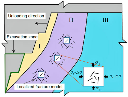
FIGURE 1. Stress-state model of the slope crack under the conditions of excavation and unloading.
During slope excavation of an open-pit mine, the strong unloading area (I) is a discontinuous surface in the rock mass where the rock mass is more broken than in the other areas and hence is called the strong unloading area (broken area). This broken area will not cause large landslides and is significant often for the local steps of the small-scale rock slide. The weak unloading area (II) is where the slope rock mass is not completely unloaded, and the dominant crack groups in the rock mass are under continuous propagation and coalescence under the unloading effect. Under this broken area of classification, the occurrence of large landslides is caused by the crack on the rock mass in this area. Therefore, this study mainly takes the weak unloading area as the main object to discuss the slope instability mechanism.
The rock mass of the slope in the weak unloading area (II) is not fully unloaded, and the stress state is shown in Figure 1. It is difficult to determine which plays the leading role in the horizontal stress and tensile stress generated by rock mass deformation during unloading, and it is impossible to directly calculate the stress intensity factor at the crack tip. Therefore, according to the stress superposition principle, the unloading stress state can be decomposed into a model in which the initial stress and the mining unloading stress act together, as shown in Figure 2. Here, σz is the maximum principal stress (vertical stress of the slope), σx is the minimum principal stress (horizontal stress of the slope), and Δσ is the mining unloading stress.
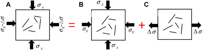
FIGURE 2. Unloading equivalent mechanical model: (A) unloading stress state, (B) biaxial loading stress state, and (C) uniaxial tensile stress state.
2.1 Analysis of crack propagation under initial stress
In this study, the slope model was simplified to a plane, two-dimensional model, and the initial stress of the sloping rock was generated by the tectonic stress and self-weight stress. It was assumed that the horizontal stress during unloading of slope excavation met the requirements, σx = K0γz[z∈(0, H)], during vertical excavation σx = 0, and the initial stress corresponding to different slope excavation angles can be expressed as follows (Huang and Huang, 2010) (Eq. 1):
where σz is the initial vertical stress of the rock unit, σx is the horizontal stress, γ is the rock mass capacity, K0 is the side-pressure coefficient, z is the distance of the unit from the upper surface of the slope, and β is the slope angle.
Figure 3 shows the schematic of the stress on the rock unit within the slope under the initial stress, where the axial stress is σz, the horizontal stress is σx, and the angle between the inclined crack and the largest main plane is α. The axial and horizontal stresses are decomposed into the tangential stress, τn, and the normal stress, σn, at the crack surface (specified as positive for tension and negative for compression), which can be expressed as follows (Eq. 2):
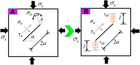
FIGURE 3. Schematic of the initiation and propagation of secondary cracks under the initial stress state: (A) secondary crack initiation and (B) secondary crack propagation.
The rock is generally controlled by the compressive stress in the initial ground stress field, the cracks within the sloping rock are closed by the normal compressive stress, and the cracks slide relatively under the action of the effective shear stress, τeff, at which point in the rock, only the type II stress intensity factor exists at the crack tip, which can be expressed as follows (Eq. 3):
where f is the sliding friction coefficient of the crack surface, τeff is the effective shear stress acting on the crack surface, a is the crack half-length, and
2.2 Analysis of crack propagation under mining stress
Figure 4 shows the schematic of the stress on the rock unit within the slope under the mining stress, where the horizontal stress is △σ and the angle between the inclined crack and the largest main plane is 90-α. The axial stress is decomposed into the tangential stress,
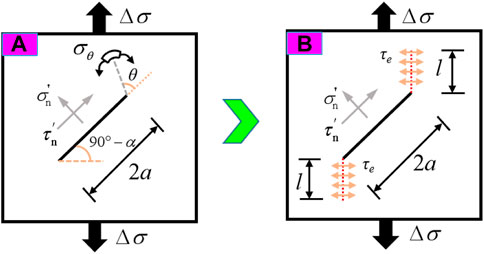
FIGURE 4. Schematic of the initiation and propagation of secondary cracks under the mining stress state: (A) secondary crack initiation and (B) secondary crack propagation.
When the crack is subjected to unidirectional tension, the crack undergoes shear sliding under the influence of shear stress along the crack surface, while the normal tensile extension is generated under normal tensile stress. According to the definition of the stress intensity factor, in the tensile–shear stress state, when the crack is subjected to the joint action of tangential shear stress, τn, and normal tensile stress, σn, I–II composite damage occurs, following which the stress intensity factor at the tip of the initial crack can be obtained as follows (Eq. 5):
where
2.3 Crack initiation conditions and propagation direction of an excavation slope
According to the principle of stress superposition, the tip stress intensity factor of a crack under a complex load is equal to the sum of the stress intensity factors of a crack tip under a simple load, and by combining Eqs 1–5, the stress intensity factor at the tip of the initial crack at distance H from the upper surface of the slope under the action of excavation and unloading can be calculated as follows (Eq. 6):
According to the maximum circumferential tensile stress criterion, the I–II composite crack will expand in the direction of the maximum tensile stress, and the starting angle x satisfies the following expression (Wang et al., 2015) (Eq. 7):
The conditions for crack initiation and propagation can be obtained as follows (Eq. 8):
where
With this, let the unloading factor
Let the left-hand side of Eq. 9 be equal to R, then the crack initiation angle
The aforementioned equation is the expression of the crack cracking angle under the unloading condition, and it can be seen that the cracking angle is related to the friction coefficient, side-pressure coefficient, unloading coefficient, and slope angle.
According to the previous analysis on the distribution of stress in the rock mass of the slope, it is known that the unloading stress is equivalent to a reverse tensile stress applied under the action of the initial ground stress in the rock mass, and this tensile stress will gradually decrease to 0. Therefore, the expression that can be obtained after taking the great value
From Eq. 11, it can be seen that the factors affecting the initiation angle include the side-pressure coefficient, friction coefficient, slope angle, and crack angle, and the specific relationship is shown in Figure 5. When the slope excavation unloads, the horizontal stress is instantly released; at this time, the crack propagation is mainly affected by the vertical stress; under the action of vertical stress, the initiation angle decreases with the increase in the crack inclination and gradually tends to the crack direction.
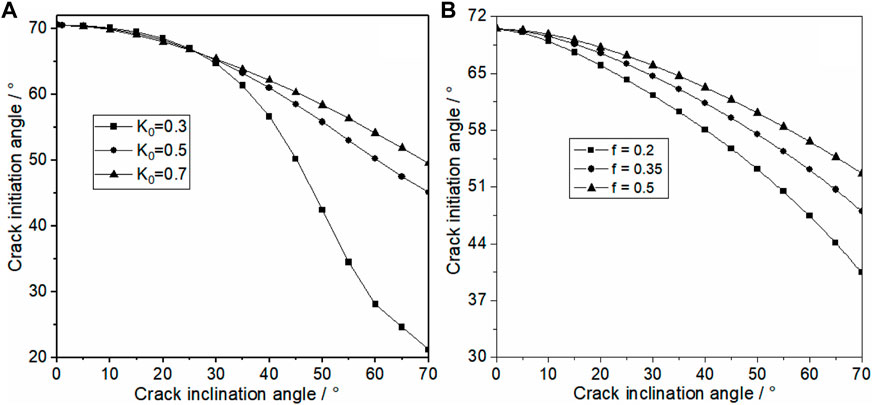
FIGURE 5. Variation in the crack initiation angle with the crack dip angle: (A) influence side of the side-pressure coefficient and (B) influence of the side-friction coefficient.
As shown in Figure 6, the initiation angle increases with the increase in the slope angle, and when the slope angle is less than 50°, the change in the initiation crack angle depends greatly on the change in the dip angle of the crack, which is because when the slope angle is less than 50°, the horizontal stress is larger and the horizontal unloading has more influence on the crack propagation. When the slope angle is greater than 50°, the horizontal stress is smaller and the horizontal unloading has little effect on the crack propagation; at this time, the fracture is equivalent to the vertical stress only under the action of crack propagation, and the cracking angle tends to the direction of the maximum main stress, which corresponds to the uniaxial compression splitting damage form of rock samples.
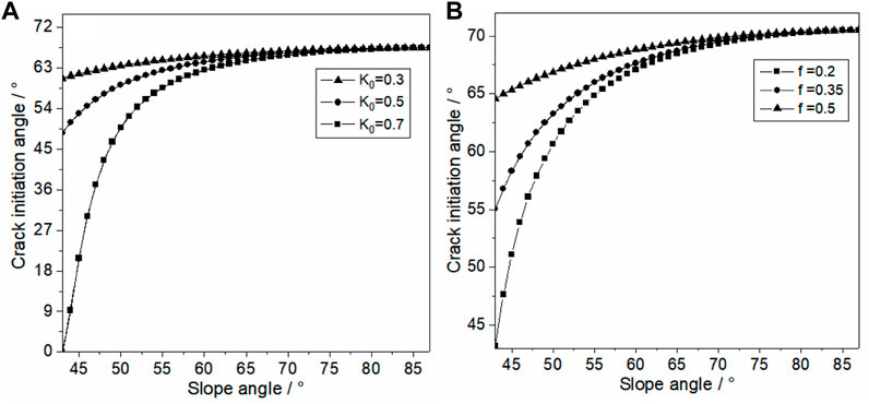
FIGURE 6. Variation in the crack initiation angle with the slope angle: (A) influence of the side-pressure coefficient and (B) influence of the side-friction coefficient.
3 Model of unloading dynamic safety height of a slope
Substituting the stress intensity factor of the crack tip under the unloading condition into Eq. 8, the ultimate safety height of the slope under the unloading action can be obtained as follows (Eq. 12):
It can be seen from Eq. 12 that if the initial crack length, crack angle, slope angle, side-pressure coefficient, rock mass unit weight, initiation angle, and rock mass crack toughness are known, the safety height of the slope when the rock mass crack initiates during unloading can be obtained. The factors affecting the ultimate safety height of the slope include the crack length, crack angle, initiation angle (initiation angle is mainly obtained by Eq. 10, where the side-pressure coefficient and friction coefficient are included), rock capacity, side-pressure coefficient, slope angle, and fracture toughness. The rock capacity and slope angle affect the same law, which is grouped with the fracture toughness and is a fixed factor independent of the crack size and shape. The ultimate safety height of the slope is linearly related to the slope angle, rock mass capacity, and fracture toughness. The greater the fracture toughness, the stronger the ability of the rock mass to resist external disturbance. The larger the slope angle and rock mass capacity, the greater the normal stress acting on the crack surface by the slip body, which is not conducive to cracking of the rock mass.
The distribution of the original crack length and crack dip angle within the rock mass of the slope has an important influence on the strength of the rock mass, which is directly related to the stability state of the slope. According to the geological survey results of the collapsed profile at the site, the distribution of the crack pattern is drawn as shown in Figure 7. The stratigraphic structure of this mine is simple, and the rock mass is more developed under the action of geological and tectonic movements and external environmental loads. The crack length is mainly concentrated between 0.11 and 0.21, and a small number of short-spaced cracks are randomly and irregularly scattered in the middle. The crack dip angle is mainly concentrated between 38° and 78°, and the remaining angle cracks are randomly and irregularly scattered between clusters. The rock weight density is 23 kN/m3, the rock fracture toughness is 1.8 MPa m1/2, and the overall angle of the slope is 46°.
(1) The evolution of the dynamic safety height of the slope with the crack dip angle
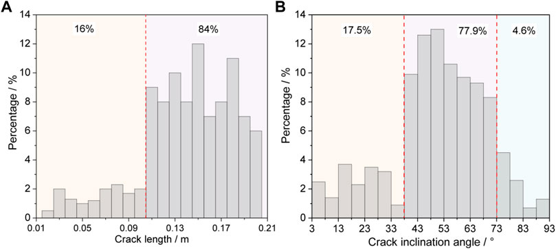
FIGURE 7. Distribution of cracks in the rock mass: (A) crack length and (B) crack inclination angle.
The variation in the ultimate safety height of the slope under different crack dip angles is shown in Figure 8. From the shape of the curve, it can be seen that under the conditions of different side-pressure coefficients and friction coefficients, the change law of the safety height of the slope with the crack dip angle is the same, showing the trend of decreasing first and then increasing. When the slit inclination angle is 52°, the safety limit height of the slope reaches the minimum, which is because the crack dip is close to the step excavation angle; meanwhile, the stress component perpendicular to the crack decreases, which is conducive to cracking and propagation of the crack under the role of unloading, and the role of unloading tensile stress is played to the maximum. When the crack dip angle is fixed, the limit height of the slope increases with the increase in the side-pressure coefficient and friction coefficient of the slope.
(2) The evolution of the dynamic safety height of the slope with the crack length
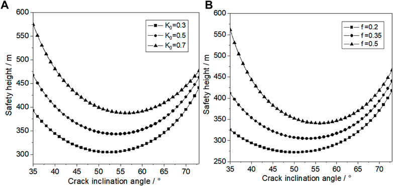
FIGURE 8. Variation in the slope safety height with the crack dip angle: (A) influence of the side-pressure coefficient and (B) influence of the side-friction coefficient.
The initial crack length within the sloping rock is an important indicator to characterize the degree and distribution of crack development. It can be seen from the curve shape in Figure 9 that the limit safety height of the slope is approximately linear with the crack length; that is, the increase of the crack length increases the risk of fracture of the cracked rock mass under unloading. Combining Figures 8, 9, it can be seen that the side-pressure coefficient has a more significant effect on the ultimate safety height of the slope than the friction coefficient. It can be seen from Figure 10 that the safety height of the slope is inversely proportional to the angle of the slope; that is, the safety height of the slope decreases with the increase in the slope angle, and the curvature of its decrease gradually decreases. When the slope angle is small, the horizontal stress is larger, the horizontal unloading has a large disturbing effect on the rock, and the slope is prone to instability damage, so the curve declines with a larger curvature.
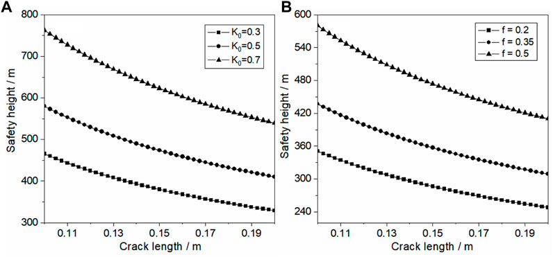
FIGURE 9. Variation in the slope safety height with the crack length: (A) influence of the side-pressure coefficient and (B) influence of the side-friction coefficient.
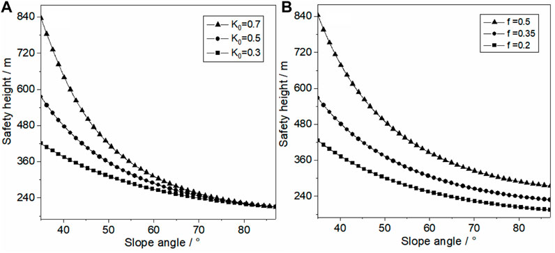
FIGURE 10. Variation in the slope safety height with the slope dip angle: (A) influence of the side-pressure coefficient and (B) influence of the side-friction coefficient.
In summary, a high degree of stress concentration will occur inside the slope of the open-pit mine with the gradual increase in the slope excavation depth; the sensitivity of the slope to the excavation unloading disturbance increases with the increase in the slope excavation depth; the unloading effect increases with the decrease in the distance from the slope surface, and the load on the rock mass of the slope increases with the decrease in the distance from the foot of the slope. When the slope height satisfies Eq. 12, the cracks on the rock mass of the slope will initiate propagation under the disturbance of unloading, and even coalescence will occur to form the macroscopic rupture surface on the rock mass and then cause the slope instability landslide.
4 Stability analysis of slope unloading
In Figure 3, under the initial stress, the initial cracks of the slope rock mass propagation are in compression and shear, and the secondary crack propagation is approximately parallel to the direction of the maximum principal stress, σz. The stress intensity factor,
where l is the secondary crack length.
In Figure 4, under the mining stress, the initial cracks of the slope rock mass propagation are in the tension–shear stress state, and the secondary crack propagation is approximately parallel to the direction of the tensile stress, △σ. The secondary crack tip stress intensity factor,
Furthermore, the secondary crack tip stress intensity factor of the slope rock mass under the unloading can be obtained as follows (Eq. 15):
Under the effect of excavation unloading, when the stress intensity factor at the tip of the secondary crack reaches the fracture toughness of the slope rock mass,
The composite stress intensity factor of the crack tip within the rock mass of the slope under the action of excavation and unloading can be calculated by Eqs 1, 6, 8 as follows (Eq. 16):
Based on the concept of fracture mechanics, the ratio of the fracture toughness of the rock mass of the slope to the composite stress intensity factor of the crack tip in the rock mass is defined as the slope stability factor, and the expression can be expressed as follows (Eq. 17):
When
5 The engineering case
In this study, a regional slope of the Dagushan open-pit iron ore mine is used as the engineering background to verify the rationality of the aforementioned model (Figure 11A). The mining level of the existing mining area of the Dagushan iron ore mine has reached −300 m, the final pit bottom elevation level of the second-phase design realm is −450 m, the slope top elevation level of the slope is between ∼70 and 190 m, and the final design height of the slope is about 650 m; the iron ore mine plans to end open-pit mining in 2026. The rock mass of the slope of the northwest gang is mainly composed of mixed rocks (titanic granite), with mud-quartz schist veins in between and stripes of iron-bearing quartzite at the bottom of the slope. The mixed rocks are widely exposed in the northwest gang of the slope, the overall strength of the rock mass is high, and the rock mass in the mining area is subjected to multiple tectonic movements, making the cracks more developed and the physical and mechanical properties of the rock layer vary greatly.
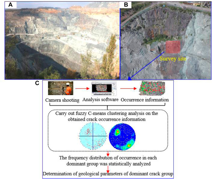
FIGURE 11. (A) Stope of Dagushan mine, (B) results of crack measurements on the slope rock mass, and (C) flow chart of fracture parameter determination.
The local rock mass in this area is more cracked under the action of initial mining, and a group of dominant cracks with nearly uniform orientation and scale in the rock mass is obtained by the non-contact 3D photogrammetry technique, with a length of about .83 m and an inclination of 40.2° (Figure 11B). The determination method of dominant crack group parameters is shown in Figure 11C. The value of the unloading tensile stress is approximated by a real triaxial unloading test, specifically by loading the field crack specimen to the original rock stress state and then starting lateral unloading; the horizontal tensile stress, σ3, changes continuously with the continuous unloading, which can be obtained by the equation,
Substituting the aforementioned parameters into Eq. 11, one can obtain the crack initiation angle; by substituting the crack initiation angle and known parameters into Eq. 12, one can obtain the dynamic safety height of the slope; the secondary crack propagation length can be found by substituting the crack initiation angle into Eq. 15; and the safety coefficient of the slope after each step of excavation can be further found by substituting crack initiation angle into Eq. 17, as shown in Figure 12. It can be seen from Figure 12 that the safety factor and dynamic safety height decreased when unloading times were increased; the safety factor and dynamic safety height decreased rapidly when unloading times were increased, which indicates that they are more prone to sudden slope instability with more unloading disturbance times. The safety factor obtained by the method proposed in this study is smaller than that obtained by the limit equilibrium method, which shows the rationality and accuracy of the method proposed in this study.
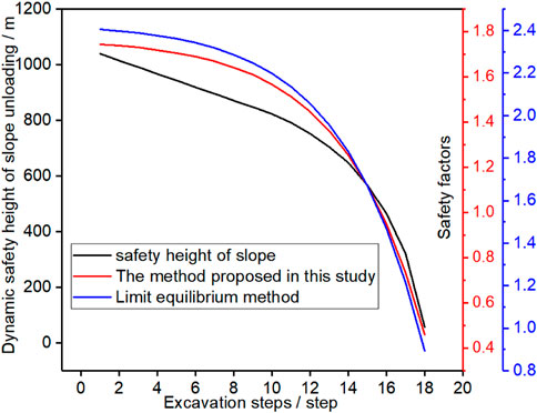
FIGURE 12. Diagram of the calculation result.
To further determine the correctness and rationality of the proposed method, continuous displacement monitoring was used to verify the method. Continuous displacement monitoring can clarify whether the slope rock mass has been displaced abruptly, and the relevant monitoring settings are shown in Figure 13A, and the displacement monitoring results are shown in Figure 13B. The displacement monitoring results in Figure 13B show that after the 17th excavation, the vertical displacement changes abruptly and the slope has already slipped at this time, while the theoretical calculation results show that after the 16th excavation, the safety coefficient of the slope is less than 1. The calculation results are conservative, which shows that the method proposed in this study is reliable.
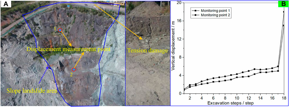
FIGURE 13. (A) Layout of the on-site measuring points and (B) displacement monitoring results.
6 Conclusion
(1) According to the principle of stress superposition, the expression of the tip stress intensity factor of the crack in the rock mass at the vertical distance H from the top of the slope under the action of excavation and unloading is derived, and the calculation method of the crack initiation angle is given. The results show a decreased crack initiation angle with an increased crack angle and an increased crack initiation angle with an increased side-pressure coefficient, friction coefficient, and slope angle.
(2) An expression for the ultimate safe height of the slope under the unloading action is derived. The ultimate safety height of the slope with the increase in crack inclination shows the change rule of decreasing first and then increasing, with the length of the crack being approximately linear and with the slope angle being an inversely proportional function.
(3) Based on fracture mechanics, the ratio of the fracture toughness of the rock mass of the slope to the composite stress intensity factor of the crack tip in the rock mass is defined as the stability coefficient of the slope. The stability coefficient calculated by the method proposed in this study is consistent with the calculation results of the limit equilibrium method and is small, which shows the accuracy and reasonableness of the method.
Data availability statement
The original contributions presented in the study are included in the article/Supplementary Material; further inquiries can be directed to the corresponding author.
Author contributions
Conceptualization, JW and ZZ; funding acquisition, ZC; methodology, JW and CC; writing—original draft, JW and ZZ; writing—review and editing, CC and HW. All authors were informed about each step of the manuscript process, including submission, revision, and revision reminder, via emails from our system or by the assigned assistant editor. All authors have read and agreed to the published version of the manuscript.
Funding
This research was funded by the National Natural Science Foundation of China (No. 52074292) and the National Key R&D Program of China (No. 2017YFC1503103).
Conflict of interest
The authors declare that the research was conducted in the absence of any commercial or financial relationships that could be construed as a potential conflict of interest.
Publisher’s note
All claims expressed in this article are solely those of the authors and do not necessarily represent those of their affiliated organizations, or those of the publisher, the editors, and the reviewers. Any product that may be evaluated in this article, or claim that may be made by its manufacturer, is not guaranteed or endorsed by the publisher.
References
Bi, J., Liu, P., and Gan, F. (2020). Effects of the cooling treatment on the dynamic behavior of ordinary concrete exposed to high temperatures. Construction and Building Materials. 248, 118688. doi:10.1016/j.conbuildmat.2020.118688
Bi, J., Tang, J. C., Wang, C. L., Quan, D. G., and Teng, M. Y. (2022). Crack coalescence behavior of rock-like specimens containing two circular embedded flaws. Lithosphere 2022 (11), 9498148. doi:10.2113/2022/9498148
Chang, Z., Cai, Q., Zhou, W., Jiskani, I. M., and Wang, R. (2019). Effects of the loading and unloading conditions on crack propagation in high composite slope of deep open-pit mine. Advances in Civil Engineering. 2019, 1–11. doi:10.1155/2019/3168481
Chen, G. Q., Liu, D., Xu, Pe., and Qin, C. A. (2010). True-triaxial test on unloading failure of jointed rock bridge. Chinese Journal of Rock Mechanics and Engineering. 29, 502–512.
Chen, J., Kang, L., and Yang, S. (2007). “Analysis of open-pit slope under excavation unloading,” in The 2007 International Conference on Mine Hazards Prevention and Control.
Chen, S. J., Zhao, Z. H., Feng, F., and Zhang, M. (2022). Stress evolution of deep surrounding rock under characteristics of bi-modulus and strength drop. Journal of Central South University. 29, 680–692. doi:10.1007/s11771-022-4945-5
Chen, S., Zhao, Z., Feng, F., and Zhang, M. (2022). Stress Evolution of deep surrounding rock under characteristics of Bi-Modulus and strength drop. Journal of Central South University. 29, 680–692. doi:10.1007/s11771-022-4945-5
Chen, Z., Li, X., Weng, L., Wang, S., Dong, L., and Perera, M. S. A. (2019). Influence of flaw inclination angle on unloading responses of brittle rock in deep underground. Geofluids 2019, 1–16. doi:10.1155/2019/4657645
Dai, B., Zhao, G., Konietzky, H., and Wasantha, P. L. P. (2018). Experimental and numerical study on the damage evolution behaviour of granitic rock during loading and unloading. KSCE Journal of Civil Engineering. 22, 3278–3291. doi:10.1007/s12205-018-1653-7
Duan, B., Zhang, M., Lv, Y., Zhai, C., and Weng, X. (2011). Stability evaluation on high rock slope of open-pit for ash storage. Applied Mechanics and Materials. 90–93, 342–346. doi:10.4028/www.scientific.net/AMM.90-93.342
Fayou, A., Kong, J. M., and Ni, Z. Q. (2012). Model test on deformation and failure of excavated anti-dip slope under seismic loading. Disaster Advances. 5, 41–47.
Feng, X. T., Xu, H., Yang, C., Zhang, X., and Gao, Y. (2020). Influence of loading and unloading stress paths on the deformation and failure features of Jinping marble under true triaxial compression. Rock Mechanics and Rock Engineering. 53, 3287–3301. doi:10.1007/s00603-020-02104-4
Gao, W., Zhuo, Z., Hou, B., and Chen, N. (2011). Road high cutting slope stability analysis under the influence of blasting for excavation. Advanced Materials Research. 250–253, 3163–3167. doi:10.4028/www.scientific.net/AMR.250-253.3163
Huang, D., and Huang, R. Q. (2010). The physical model test of deformation failure and crack propagation evolution of fractured rock mass under unloading conditions. Chinese Journal of Rock Mechanics and Engineering. 29, 502–512.
Huang, R. Q., and Huang, D. (2014). Evolution of rock cracks under unloading condition. Rock Mechanics and Rock Engineering. 47, 453–466. doi:10.1007/s00603-013-0429-0
Huang, R., Xiao, H., Ju, N., and Zhao, J. (2007). Deformation mechanism and stability of a rocky slope. Journal of China University of Geosciences. 18, 77–84. doi:10.1016/S1002-0705(07)60021-1
Huang, X., Liu, Q., Liu, B., Liu, X., Pan, Y., and Liu, J. (2017). Experimental study on the dilatancy and fracturing behavior of soft rock under unloading conditions. International Journal of Civil Engineering. 15, 921–948. doi:10.1007/s40999-016-0144-9
Jiao, Q., Wang, Y., and Jiang, W. (2022). The progressive failure mechanism of the tunnel-slope system under rainfall: An experimental investigation. Geofluids 2022, 20221–20316. doi:10.1155/2022/1775049
Kong, J., Fayou, A., Ni, Z., and Cui, Y. (2011). Effects of excavation on deformation and failure of anti-dip slopes under the action of seismic load. Applied Mechanics and Materials. 94–96, 1864–1869. doi:10.4028/www.scientific.net/AMM.94-96.1864
Li, B., Zhu, Y., Qi, F., and Yuan, Z., (2021). Failure of an under-dip shale slope and its response under excavation conditions. Journal of Engineering Research. 9, 63–72. School of Civil Engineering and Architecture, Zhongyuan University of Technology, Zhengzhou, 450007, China. doi:10.36909/JER.V9I1.8111
Li, X. B., Chen, Z. H., Wang, L., and Li, C. J. (2019). Unloading responses of pre-flawed rock specimens under different unloading rates. Transactions of Nonferrous Metals Society of China (English Edition). 29, 1516–1526. doi:10.1016/S1003-6326(19)65059-4
Ma, Q., Tan, Y., Liu, X., Gu, Q., and Li, X. (2020). Effect of coal thicknesses on energy evolution characteristics of roof rock-coal-floor rock sandwich composite structure and its damage constitutive model. Composites Part B: Engineering. 198, 108086. doi:10.1016/j.compositesb.2020.108086
Qu, M., and Dang, F. (2022). Numerical analysis of instability mechanism of a high slope under excavation unloading and rainfall. Applied Sciences. 12, 7990. doi:10.3390/app12167990
Sasahara, K., Hiraoka, N., Kikkawa, N., and Itoh, K. (2021). Development of the surface displacement velocity in a full-scale loamy model slope under multistep excavation. Bulletin of Engineering Geology and the Environment. 80, 4389–4403. doi:10.1007/s10064-021-02226-1
Song, D., Chen, J., and Cai, J. (2018). Deformation monitoring of rock slope with weak bedding structural plane subject to tunnel excavation. Arabian Journal of Geosciences. 11, 251. doi:10.1007/s12517-018-3602-7
Su, P., Qiu, P., Liu, B., Chen, W., and Su, S. (2022). Stability prediction and optimal angle of high slope in open-pit mine based on two-dimension limit equilibrium method and three-dimension numerical simulation. Physics and Chemistry of the Earth. 127, 103151. doi:10.1016/j.pce.2022.103151
Wang, D., Chen, G., Mi, G., and Zhang, G. (2020). The stability analysis of rock slide in the unloading crack zone based on fracture mechanics. Journal of Railway Engineering Society. 37, 24–30.
Wang, J., Chen, Z., and Zhang, L. (2020). Unloading-induced crack propagation of two collinear unequal length flaws in brittle rocks. Geofluids 2020, 1–18. doi:10.1155/2020/9385749
Wang, J. M., Cui, X. N., Chen, Z. H., and Chen, C. (2022). Study on the mechanism and stability of unloading fracture in rock slopes containing trailing edge cracks in an open-pit mine. Chinese Journal of Geotechnical Engineering, 1–10.
Wang, L. G., Xi, Y. H., and Liu, X. F. (2015). Analysis on stress state adjustment and collapse of rock slope subject to seismic loads. China Civil Engineering Journal. 48, 109–115.
Yang, Y., Sun, G., Zheng, H., and Qi, Y. (2019). Investigation of the sequential excavation of a soil-rock-mixture slope using the numerical manifold method. Engineering Geology. 256, 93–109. doi:10.1016/j.enggeo.2019.05.005
Zhang, J. Z., Zhou, X. P., Zhu, J. Y., Xian, C., and Wang, Y. T. (2018). Quasi-static fracturing in double-flawed specimens under uniaxial loading: The role of strain rate. International Journal of Fracture. 211, 75–102. doi:10.1007/s10704-018-0277-8
Zhang, K., Tan, P., Ma, G., and Cao, P. (2016). Modeling of the progressive failure of an overhang slope subject to differential weathering in Three Gorges Reservoir, China. Landslides 13, 1303–1313. doi:10.1007/s10346-015-0672-4
Zhang, S., Pei, X., Wang, S., Huang, R., and Zhang, X. (2020). Centrifuge model testing of loess landslides induced by excavation in northwest China. International Journal of Geomechanics. 20, 1–18. doi:10.1061/(asce)gm.1943-5622.0001619
Zhao, X. G., Wang, J., Cai, M., Cheng, C., Ma, L. K., Su, R., et al. (2014). Influence of unloading rate on the strain burst characteristics of Beishan granite under true-triaxial unloading conditions. Rock Mechanics and Rock Engineering. 47, 467–483. doi:10.1007/s00603-013-0443-2
Zhao, Y., and Zhang, G. (2020). Centrifuge modeling of soil slopes overlying bedrock under excavation conditions. Soils Found. 60, 886–897. doi:10.1016/j.sandf.2020.06.009
Zhao, Z., Sun, W., Chen, S., Feng, Y., and Wang, W. (2020). Displacement of surrounding rock in a deep circular hole considering double moduli and strength-stiffness degradation. Applied Mathematics and Mechanics (English Edition). 41, 1847–1860. doi:10.1007/s10483-020-2665-9
Zhong, Z., Huang, D., Zhang, Y., and Ma, G. (2020). Experimental study on the effects of unloading normal stress on shear mechanical behaviour of sandstone containing a parallel fissure pair. Rock Mechanics and Rock Engineering. 53, 1647–1663. doi:10.1007/s00603-019-01997-0
Zhou, X.-P., Zhang, J.-Z., and Berto, F. (2020). Fracture analysis in brittle sandstone by digital imaging and AE techniques: Role of flaw length ratio. Journal of Materials in Civil Engineering. 32, 1–17. doi:10.1061/(asce)mt.1943-5533.0003151
Zhou, X. P. (2005). Localization of deformation and stress-strain relation for mesoscopic heterogeneous brittle rock materials under unloading. Theoretical and Applied Fracture Mechanics. 44, 27–43. doi:10.1016/j.tafmec.2005.05.003
Zhou, X. P., Zhang, J. Z., Qian, Q. H., and Niu, Y. (2019). Experimental investigation of progressive cracking processes in granite under uniaxial loading using digital imaging and AE techniques. Journal of Structural Geology. 126, 129–145. doi:10.1016/j.jsg.2019.06.003
Zhou, X. P., Zhang, J. Z., and Wong, L. N. Y. (2018). Experimental study on the growth, coalescence and wrapping behaviors of 3D cross-embedded flaws under uniaxial compression. Rock Mechanics and Rock Engineering. 51, 1379–1400. doi:10.1007/s00603-018-1406-4
Zhou, Z., Chen, Z., Shen, Y., Bao, M., Nian, G., Zhang, L., et al. (2021). Failure of rock slopes with intermittent joints: Failure process and stability calculation models. Lithosphere 2021, 8923718. doi:10.2113/2022/8923718
Zhou, Z., Pi, Z., Jing, Y., and Wang, S. (2022). Responses of pre-holed granite under coupled biaxial loading and unloading stress condition. Minerals 12, 372. doi:10.3390/min12030372
Zhou, Z., Shen, Y., Zhang, H., Wang, Y., Yang, H., Pan, J., et al. (2021). Sandstone-concrete interface debonding mechanism under freeze-thaw actions: Fracture process and fracture criterion. Construction and Building Materials 294, 123526. doi:10.1016/j.conbuildmat.2021.123526
Keywords: excavation unloading, crack initiation angle, stress intensity factor, safety factor, rock mass
Citation: Wang J, Zhou Z, Chen C, Wang H and Chen Z (2023) Failure mechanism and stability analysis of an open-pit slope under excavation unloading conditions. Front. Earth Sci. 11:1109316. doi: 10.3389/feart.2023.1109316
Received: 27 November 2022; Accepted: 02 January 2023;
Published: 19 January 2023.
Edited by:
Xiaoping Zhou, Chongqing University, ChinaReviewed by:
Hao Cheng, Wuhan University, ChinaHaijia Wen, Chongqing University, China
Jing Bi, Guizhou University, China
Copyright © 2023 Wang, Zhou, Chen, Wang and Chen. This is an open-access article distributed under the terms of the Creative Commons Attribution License (CC BY). The use, distribution or reproduction in other forums is permitted, provided the original author(s) and the copyright owner(s) are credited and that the original publication in this journal is cited, in accordance with accepted academic practice. No use, distribution or reproduction is permitted which does not comply with these terms.
*Correspondence: Zihan Zhou, MTg4MTMwMjczNjlAMTYzLmNvbQ==