 Shi Wei
 Hong Zenglin1*
 Yang Min
94% of researchers rate our articles as excellent or good
Learn more about the work of our research integrity team to safeguard the quality of each article we publish.
Find out more
ORIGINAL RESEARCH article
Front. Earth Sci., 15 February 2023
Sec. Environmental Informatics and Remote Sensing
Volume 11 - 2023 | https://doi.org/10.3389/feart.2023.1104865
This article is part of the Research TopicAdvances in Development and Utilization of Underground SpaceView all 17 articles
In recent years, the development of urban underground space in China, especially the construction and operation of subway tunnels, has greatly relieved the pressure of urban traffic. Due to the imperfect planning of urban facility, many subway tunnels have to be built under the existing utility tunnels (pipe galleries). Nevertheless, shield construction of subway tunnel has a great adverse impact on the deformation and safety of the existing pipe gallery. Therefore, this paper takes Xi’an Metro Line 2 as an example, and studies the safety depth for subway tunnel shield construction under different regional conditions in Xi’an through numerical simulation. The results show that the deformation of the existing pipe gallery and its influence range decrease with the rising buried depth of the double-line subway tunnel when the soil properties are good. For example, in the loess tableland area, when the buried depth of the subway tunnel is greater than 12 m, the settlement deformation of the pipe gallery basically meets the control standard. When the soil properties are poor or the soil properties vary greatly, the subway tunnel excavation has a great impact on the safety of the pipe gallery. For example, in the first-level alluvial fan area with sand layer, when the buried depth of the subway tunnel is less than 24 m and more than 12 m, the deformation standard cannot be satisfied. In addition, in the first-level alluvial fan area with sand layer, the lower soil layer should be treated or the construction parameters should be optimized before the excavation of subway tunnel. The research results can provide reference for similar engineering construction.
In cities, utility tunnels are underground structures commonly used to transport water, sewage, oil, gas, etc. Utility tunnels have been constructed throughout the world since their first appearance in Paris in 1851. With the rapid expansion of underground space, the construction of underground structures will inevitably lead to the change of the surrounding stress field and displacement field, which will greatly affect the stability of the existing underground structures around them (Chen et al., 2011a; 2011b; Ma et al., 2017). How to reduce the mutual influence between tunnel lines is an urgent problem to be solved in the construction of underground buildings in the future.
Most of the previous studies focus on the seismic response of underground pipe galleries (Li et al., 2009; Shi et al., 2010; Tang et al., 2009; You. 2011; Luo. 2013; Ye. 2014; Shamsabadi et al., 2001; 2002; Dashti et al., 2016; Kimura et al., 2005; Qin et al., 2022; Li et al., 2023; Liu et al., 2022a). But with the rapid growth of underground pipe galleries in recent years, ground fracture, a special geological disaster, has brought great challenges to the construction of underground pipe galleries. Therefore, many scholars have shifted their research focus to the impact of ground factures on underground pipe galleries (Zhu. 2018; Hu et al., 2019; Ma et al., 2019; Yang et al., 2019; Yan et al., 2018; Yan 2019). Some have also studied the mechanical characteristics of underground utility tunnel during its construction. For example, Hu and Xue (2010) studied the mechanical characteristics of prefabricated prestressed utility tunnel through monotone static test. Duan et al. (2020), based on the actual monitoring data of post-construction settlement of a high loess filling site in Shaanxi province, investigated the stress deformation state of the underground utility tunnel at the combined position of excavation and filling through physical tests.
With the increase of the number of underground pipe galleries, various problems have emerged one after another, especially when they are close to or crossing under existing buildings (structures) (You 2017). Some achievements have been made in the research on the joint construction of underground utility tunnel and urban subway. For example, Zhao et al. (2018) conducted a numerical simulation analysis on the impact of the explosion in the natural gas compartment of the utility tunnel on the adjacent subway tunnel. Gao and Haifeng (2018) analyzed the tunneling conditions with and without reinforcement measures during the excavation of underground utility tunnel that crosses existing subway tunnel. Feng et al. (2018) simulated the open-cut construction process of underground utility tunnel of Metro Line 1 in Baotou through finite element software Midas-GTX, and analyzed the influence of the open-cut construction on the structure of nearby subways. Peng (2017) studied the technical feasibility of simultaneous construction of utility tunnel and subway. Wu (2017) used ABAQUS to conduct finite element modeling on the excavation process of the underground utility tunnel in Tongzhou, Beijing, and analyzed the impact of the excavation process on the tunnel structure and surrounding soil. Yang et al. (2019) studied the reinforcement measures that should be taken when the underground utility tunnel in the soft soil area of Kunming is close to the existing subway. Wang and Jiang (2019) took the project of an underground utility tunnel in Beijing as an example to analyze and optimize the construction scheme of comprehensive utility tunnel passing through the existing subway. Yang et al. (2020, 2021) studied the interaction between subway and comprehensive tunnel in loess area. The existing research mainly focuses on the construction technology, the mechanical effect of underground utility tunnel, and the influence of utility tunnel construction on the existing subway, but there are few reports on the influence of subway construction on the deformation of the existing utility tunnel. More in-depth research and analysis should be carried out on the large-scale construction of underground pipe galleries and subways in the future. It is therefore of great practical significance to investigate the interaction between underground utility tunnel and existing subway under different regional conditions.
Based on a Metro shield tunnel project in Xi’an, this paper numerically simulates and analyzes the influence of three-dimensional dynamic construction of shield tunnel on the displacement of existing underground utility tunnel under different regional conditions and subway buried depths, so as to provide reference for similar projects.
According to the hydrogeological survey data, Xi’an is mainly divided into seven regions: the first-level alluvial fan, the second-level alluvial fan, the third-level alluvial fan, the first-level terrace of Weihe River, the second-level terrace of Weihe River, the third-level terrace of Weihe River, and the loess tableland. These regions have different soil layer distribution as well as soil parameters. According to regional soil characteristics, this paper selects the loess tableland, first-level terrace of Weihe River, and first-level alluvial fan as the research objects.
Because the soil layer distribution in each area is quite different, three typical areas are selected for numerical simulation in this paper. The soil layer in the loess tableland area is mainly loess alternating with paleosol, and the soil quality is relatively stable. In the first-level terrace of Weihe River, the overburden layer is plain fill and loess-like soil, and the bottom layer is alternately medium sand and silty clay, and the soil property parameters are poor. The soil layer of the first-level alluvial fan is composed of plain fill and loess in the upper part, and silty clay and coarse sand in the lower part.
The subway shield tunnel of Xi’an Metro Line 2 is the research object of this paper. It is a double-line tunnel with parallel right and left lines and circular cross section. The panel-meter earth pressure balance shield machine is adopted for tunneling. Prefabricated C50 reinforced concrete pipes are used for supporting, and they are connected by bending bolts. The outer diameter of pipes is 6.0 m, the ring width is 1.5 m, and the thickness is generally 300 mm.
The subway tunnel will be built under an existing utility tunnel (to distinct it from subway tunnel, it will be referred to as pipe gallery hereinafter) in Xi’an. The axes of the subway tunnel and the pipe gallery are on the same vertical line. The relative position relationship between a tunnel section and the underground pipe gallery is shown in Figure 1. The pipe gallery is a typical asymmetric three-cabin project consisting of a natural gas cabin, an integrated cabin and a power cabin from left to right. Their specific dimensions are shown in Figure 2.
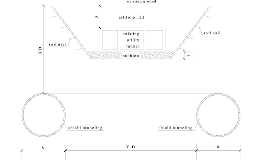
FIGURE 1. Relative position of tunnel and pipe gallery (unit: m).
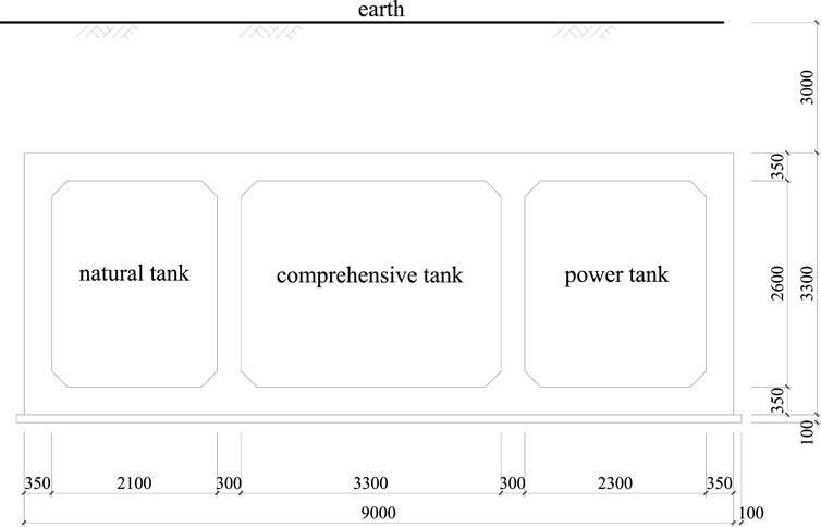
FIGURE 2. Dimensions of the underground pipe gallery (unit: mm).
The underground pipe gallery adopts the economical open-cut method, and its buried depth is 3 m. The pipe gallery structure is cast with C35 concrete. After the excavation, the reinforcement method of sloping and soil nailing was adopted. The slope was 1:0.75. After the soil nails was applied, wire mesh was fixed on the slope surface, which was then sprayed with C20 concrete. The soil nails are HRB400 steel bars with a diameter of 14 mm, and their vertical spacing and longitudinal spacing are 1.5 m and 1.0 m respectively. The thickness of the shotcrete support is 60 mm. After the foundation pit is excavated to the bottom, the cushion with a thickness of 1.0 m is poured with C15 concrete in time. The left and right sides of the pipe gallery foundation pit are the same, so only the schematic diagram of the left half of the foundation pit is shown in Figure 3.
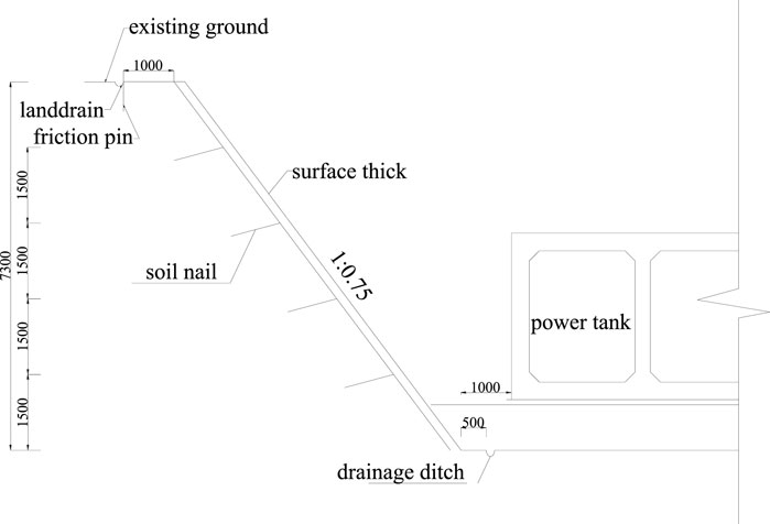
FIGURE 3. Schematic diagram of the left half of the pipe gallery (unit: mm).
With strong pre-processing ability, the finite element software ANSYS can provide a variety of subdivision methods according to user requirements, and can control the mesh size. The finite difference software FLAC3D can provide constitutive models of 11 kinds of materials, which are divided into three groups: cavitation, elasticity and plasticity. Each model represents the physical model of constitutive relations of some specific rock and soil. Therefore, this paper uses ANSYS to establish the numerical model, and then inputs it into FLAC3D for numerical simulation calculation.
In order to investigate the influence of soil properties and subway tunnel burial depth on the deformation of the existing pipe gallery, this paper designs the following calculation conditions, as shown in Table 1.
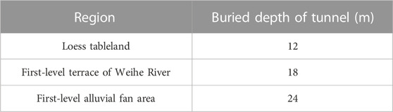
TABLE 1. Calculation conditions.
The construction footage of the shield tunnel simulated in this paper is 1.5 m, that is, the tunneling distance of each excavation is the ring width of one pipe pieces, and the simplified treatment is as follows.
(1) The longitudinal length of the model is 60 m, that is, the length of 40 pipe pieces. Herein, the shell of the shield machine and the pipe are discretionally divided according to the ring width. In order to better simulate the size of the shield machine, the total length of the shield machine is set to 9.0 m, that is, the length of 6 pipe pieces.
(2) The tunnel structure and pipe gallery structure both adopt linear elastic constitutive relationship.
(3) The pipe pieces are regarded as a whole, regardless of the pipe connection.
Given that the influence range of tunnel excavation is about 2–3 times the hole diameter, the model size is set to 90 × 60 × 50 m, as shown in Figure 4. Solid elements are used for soil layer, backfill soil, cushion and pipes, among which, soil layer adopts Moore Coulomb model, and cushion and pipes adopts elastic model. The shell of shield machine is simulated by shell element, while the grouting layer, soil nail wall layer and main structure of pipe gallery are calculated by solid element and elastic model. The soil nail is embedded into the soil and surface layer with cable structural unit. Displacement boundary conditions of the model: horizontal constraints are imposed on the vertical boundary, free constraints on the top, and vertical and horizontal constraints on the bottom. A vertical downward force of gravity is applied to the entire model.
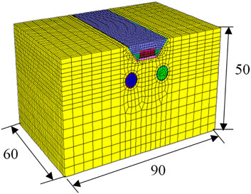
FIGURE 4. Diagram of model (unit: m).
The open-cut method is used to excavate the utility tunnel. The excavation depth of the foundation pit is divided into two excavations. The first excavation is 4 m and the second excavation depth is 3.3 m. In addition, the slope of the foundation pit will be sprayed and soil nailed immediately after excavation in the project. Pit bottom immediately after the cushion construction to prevent excessive exposure of the pit bottom soil.
The simulation process is divided into three stages: (1) the geostress equilibrium of the model under the action of gravity only, (2) excavation of the existing underground pipe gallery, that is, simulation of the deformation and settlement caused by open excavation and casting of the pipe gallery tunnel, and (3) excavation of a double-line subway tunnel beneath the existing pipe gallery. This paper mainly studies the calculation results of the third stage, so after the calculation of the first and second stages, the displacement of soil and structure is reset to zero. Thus, the deformation of the existing pipe gallery is essentially the displacement increment of the pipe gallery caused by the excavation of the new double-line subway tunnel.
In this paper, the physical and mechanical parameters of the soil layers in the three study areas are from the survey data provided by Shaanxi Hydrogeology, Engineering Geology and Environment Geology Survey Center, and the experimental values of the mechanical parameters of loess (Zhu et al., 2010a; Zhang et al., 2022a; 2022b; Liu et al., 2022b). Table 2∼ Table 4 present the soil properties of the soil layers in the three regions and the thickness of each layer determined according to the survey data.
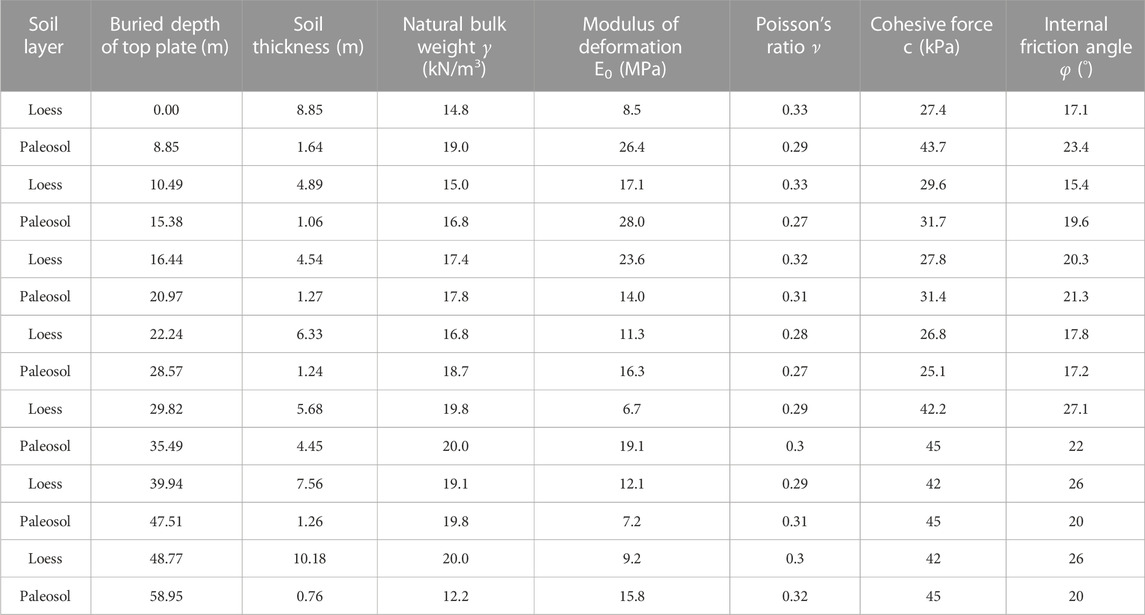
TABLE 2. Soil properties of loess tableland.
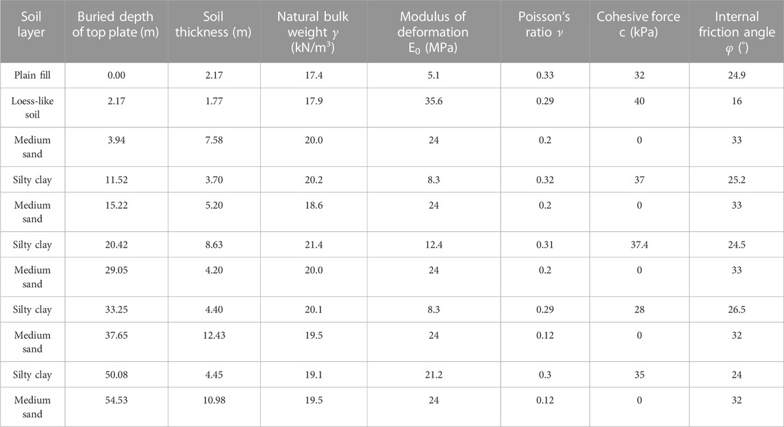
TABLE 3. Soil properties of first-level terrace of Weihe River.
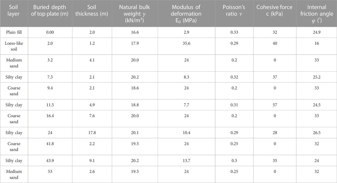
TABLE 4. Soil properties of the first-level alluvial fan.
The pipes of shield tunnel are made of C50 reinforced concrete. Considering the influence of the stiffness reduction of the spliced pipes, the elastic modulus of the pipe is reduced by 20%, and the elastic modulus of the grouting slurry is determined according to the initial strength and late strength (Zhu et al., 2010b; 2011). During excavation of shield tunnel, the surrounding rock and soil cannot directly contact the pipes (lining), so the gap is filled with grout. To simplify the calculation in the simulation analysis, the mixture of the grouting slurry and the surrounding rock and soil is simplified into a homogeneous equivalent layer, with a thickness of 30 cm. The early and late stages in Table 4 are the early and late stages after grouting between the pipe and the surrounding rock. The weighting method is used to determine the modulus of the soil nail wall of the pipe gallery, and the corresponding structures are simplified into elastic models. The parameters are determined according to Ministry of Housing and Urban-Development of the People's Republic of China (2011) and Ministry of Housing and Urban-Development of the People's Republic of China (2015), as shown in Table 5.
TABLE 5. Structural parameters of subway tunnel and pipe gallery.
The monitoring time is the time when the right and left tunnel lines are excavated to the middle of the pipe gallery. Monitoring points are arranged at the midpoint of each chamber in the longitudinal central section of the pipe gallery, as shown in Figure 5.
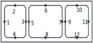
FIGURE 5. Layout of monitoring points.
The utility tunnel is a gallery for carrying multiple pipelines, and its deformation control standard is stricter than the general pipeline control standard. However, due to the imperfect regulations on the pipe gallery, according to specification (Ministry of Housing and Urban-Rural Development of the People's Republic of China, 2013), the relevant deformation standard with importance level I is taken as the benchmark, that is, the maximum settlement is −10 mm. In addition, the maximum uplift herein is set to 5 mm according to the control standard of subway. Since the maximum horizontal displacement of the existing pipe gallery caused by subway tunnel excavation is only 0.3 mm, the vertical deformation of the pipe gallery is mainly analyzed in this paper.
According to the distribution of soil layers in the loess tableland, the corresponding mechanical parameters are assigned to the model. After the excavation of shield tunnel is completed, the deformation at the monitoring point 30 m away from the portal of the pipe gallery is analyzed. The vertical displacement of pipe gallery and subway tunnel under different buried depths is illustrated in Figure 6, and the vertical displacement curves of the monitoring points are shown in Figure 7.
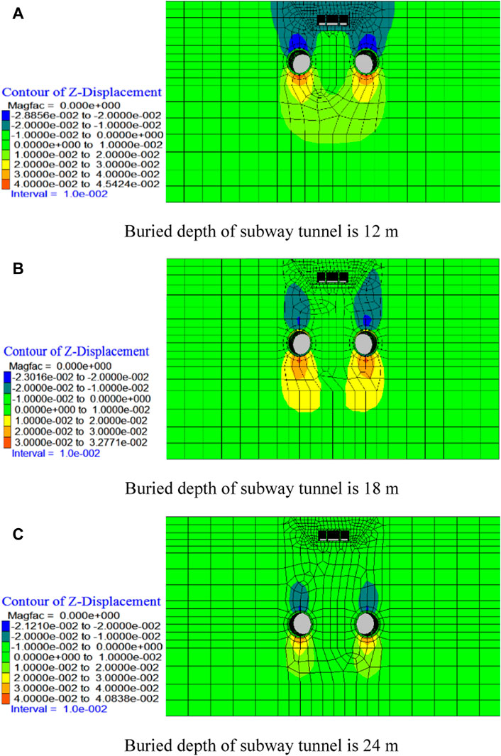
FIGURE 6. Vertical displacement diagram under different tunnel burial depths (unit: m).
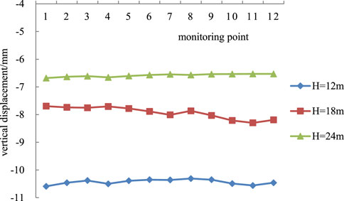
FIGURE 7. Vertical displacement curves of monitoring points in the pipe gallery.
As shown in Figure 6, the excavation of the new tunnel causes the disturbance of the soil mass, which leads to the displacement of the surrounding rock and soil of the existing pipe gallery. It can be seen that the excavation of the tunnel mainly causes deformation of the soil beneath the pipe gallery—settlement of the soil towards the tunnel. With the increase of tunnel depth, that is, the spacing between the two increases, the influence of tunnel excavation on the stability of the existing pipe gallery decreases.
It can be seen from Figure 7 that as the tunnel buried depth rises, that is, the distance between the tunnel and the pipe gallery increases, the settlement and deformation of the existing pipe gallery decreases. In other words, the influence of soil disturbance on the pipe gallery is reduced, which is clearly shown in the displacement diagram. The maximum settlement of pipe gallery occurs when the tunnel depth is 12 m, and the maximum vertical displacement is 10.5 mm. When the tunnel depth is 24 m, the settlement deformation of pipe gallery reaches its minimum of 7 mm. The settlement curve is roughly a straight line, that is, the pipe gallery is disturbed and produces uniform settlement. This is because the double-line subway is excavated in the same direction at the same time. According to the standard for deformation control of utility tunnel (the allowable maximum settlement is −10 mm, and the maximum uplift is 5 mm), when the tunnel buried depth is greater than 12 m, the deformation criterion is met. Therefore, it is recommended to excavate the right and left lines of the shield tunnel in the same direction at the same time, which can not only ensure the safety of the existing pipe gallery, but also speed up the construction progress of the project.
According to the distribution of soil layer in Weihe first-level terrace, the corresponding mechanical parameters of each soil layer are assigned to the model. The deformation at the monitoring points 30 m away from the front portal of pipe gallery is analyzed after tunnel excavation. The vertical displacement diagrams of pipe gallery and subway tunnel are shown in Figure 8, and the vertical displacement curves of monitoring points are shown in Figure 9.
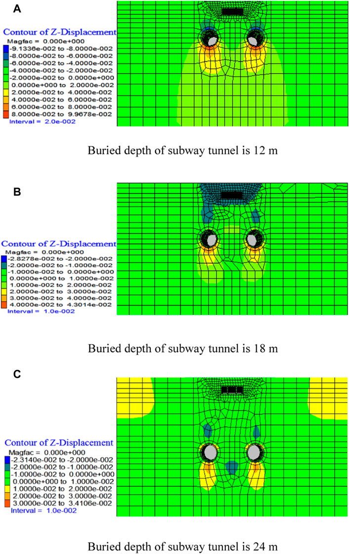
FIGURE 8. Vertical displacement diagram under different tunnel burial depths (unit: m).

FIGURE 9. Vertical displacement curves of monitoring points in the pipe gallery.
As shown in Figure 8, the excavation of subway tunnel mainly causes the deformation of the soil below the pipe gallery, that is, the settlement of the soil towards the subway tunnel. When the tunnel depth is 12 m, the tunnel excavation has the greatest impact on the pipe gallery, while when the tunnel depth is 18 m, this impact is the smallest.
As shown in Figure 9, in the first-level terrace area of Weihe River, the vertical displacement of the pipe gallery does not decrease with the rising tunnel buried depth. When the tunnel depth is 12 m, the vertical displacement of the pipe gallery is the largest, and when the tunnel depth is 18 m, its vertical displacement is the smallest. This is because the strata of 20–30 m in the first class terrace area of Weihe River are alternately distributed with medium-fine sand and silty clay, and the soil condition is poor. Therefore, when the tunnel depth is 24 m, the disturbance to the pipe gallery is greater than that when the tunnel depth is 18 m. But such disturbance is smaller in the case of an 18 m buried depth than a 12 m buried depth due to the increasing spacing, which is clearly shown on the displacement diagram. The maximum settlement of pipe gallery occurs when the tunnel buried depth is 12 m, in which case the maximum vertical displacement is 22.7 mm. Under the same spacing, the deformation curve can be roughly seen as a straight line, that is, the pipe gallery has uniform settlement. This is caused by the excavation of the double-line subway tunnel in the same direction at the same time. According to the standard for deformation control of utility tunnel (i.e., the allowable maximum settlement is −10 mm, and the maximum uplift is 5 mm), when the tunnel buried depth is smaller than or equals 24 m, the deformation criterion cannot be satisfied. In that case, reinforcement measures should be taken for the existing pipe gallery.
According to the distribution of the soil layer in the first-level alluvial fan area, the corresponding mechanical parameters are assigned to each soil layer of the model. Similarly, the deformation at the monitoring points 30 m away from the front portal of pipe gallery is analyzed after tunnel excavation. Figure 10 shows the vertical displacement diagram of the pipe gallery under different buried depths. Figure 11 shows the vertical displacement curves of different monitoring points.
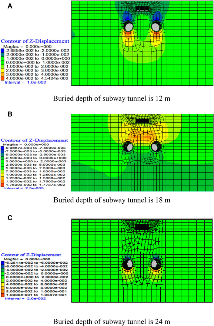
FIGURE 10. Vertical displacement diagram under different tunnel burial depths (unit: m).
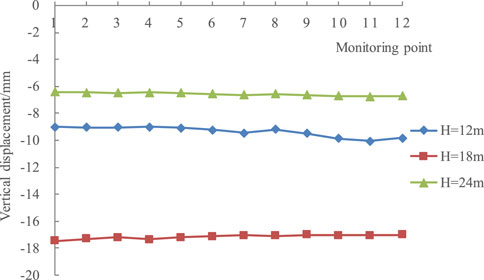
FIGURE 11. Vertical displacement curves of monitoring points in the pipe gallery.
It can be observed from Figure 10 that the excavation of subway tunnel mainly causes the deformation of the soil beneath the pipe gallery, i.e., the settlement of soil towards the subway tunnel. When the tunnel depth is 18 m, the excavation has the greatest influence on the pipe gallery, while when the tunnel depth is 24 m, this impact is the smallest.
As shown in Figure 11, in the first-level alluvial fan area, the vertical displacement of the pipe gallery does not decrease with the rising tunnel buried depth. The vertical displacement of the pipe gallery is the largest under an 18 m tunnel buried depth, but the smallest under a 24 m tunnel buried depth. The reason is that the lower soil layer of the first-level alluvial fan area is alternately distributed with coarse sand and silty clay. When the tunnel buried depth is 18 m, the corresponding stratum is composed of coarse sand, and the soil condition is poor, so the excavation has the greatest impact on the upper area. Therefore, the disturbance to the pipe gallery under an 18 m buried depth is larger than that under a 12 m buried depth, in which case the settlement of the pipe gallery is larger, as shown in the displacement diagram. The maximum settlement of pipe gallery occurs when the tunnel buried depth is 18 m, and the maximum vertical displacement is 18 mm. In addition, under the same buried depth, the deformation curve can be roughly seen as a straight line. That indicates that the existing pipe gallery is disturbed and produces uniform settlement, which is caused by the excavation of double-line subway tunnel in the same direction at the same time. When the tunnel depth is 24 m, the settlement deformation of the pipe gallery is the minimum, with a value of 6.2 mm. According to the standard for deformation control of utility tunnel (i.e., the allowable maximum settlement is −10 mm, and the maximum uplift is 5 mm), when the tunnel buried depth is 12 m and 24 m, the deformation criterion can be satisfied. Therefore, it is suggested to excavate the two lines of the shield tunnel in the same direction at the same time, which not only ensures the safety of the existing pipe gallery, but also speeds up the construction progress of the project. By contrast, when the tunnel buried depth is 18 m, the deformation criterion cannot be met. In this case, it is necessary to take measures to reinforce the existing pipe gallery.
The subsection compares the influence of tunnel excavation on the stability of existing pipe gallery under different soil properties when the tunnel depth is constant. Figure 12 and Figure 14 show that the vertical displacement curves of monitoring points in the existing pipe gallery under different tunnel buried depths.
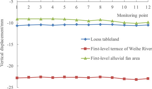
FIGURE 12. Vertical displacement curves under a 12 m tunnel buried depth.
It can be seen from Figure 12 that the excavation of subway tunnel in the first-level alluvium fan area has the smallest impact on the existing pipe gallery, with a vertical displacement of pipe gallery of about 9.5 mm, followed by that in the loess tableland, with a vertical displacement of about 10.5 mm. According to the standard for deformation control of utility tunnel, the stability of pipe gallery in these two areas can satisfy the deformation criterion. The excavation of the subway tunnel on the first-level terrace of Weihe River has the greatest impact on the pipe gallery, and the maximum vertical displacement of pipe gallery is 23 mm. According to the standard for deformation control of utility tunnel, the pipe gallery stability in this case cannot meet the deformation criterion. This is because the soil in the lower part of the Weihe first-level terrace is alternately distributed with silty clay and medium sand, and the tunnel is basically in the medium sand layer with poor soil conditions. Thus, the excavation has the greatest impact on the structure above.
As shown in Figure 13, the excavation of subway tunnel in the Loess tableland area has the smallest impact on the existing pipe gallery, and the vertical displacement of pipe gallery is basically 8 mm. According to the standard for deformation control of utility tunnel, the stability of the pipe gallery can roughly satisfy the deformation criterion. The subway tunnel excavation in the fist-level alluvial fan area has the second smallest impact on the pipe gallery stability, with a vertical displacement of 17 mm. In this case, the stability of the pipe gallery cannot meet the deformation criterion. This is because when the buried depth is 18 m, the tunnel is in the layer consisting of silty clay and coarse sand, and the soil property is poor. As a result, the excavation has a great impact on the structure above. The excavation of the subway tunnel in the first-level terrace of Weihe River has the greatest impact on the existing pipe gallery, and the maximum vertical displacement of pipe gallery is 20.1 mm. According to the standard for deformation control of utility tunnel, the stability of the pipe gallery cannot satisfy the deformation criterion. This is because the lower soil layer of the first-level terrace of Weihe River is alternatively distributed with silty clay and medium sand, and the tunnel is basically located in the silty clay layer. Additionally, the overall soil property of the first-level terrace of Weihe River is poor, and the upper and lower layers are medium sand, so the excavation has the greatest impact on the structure above.
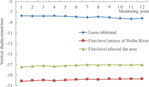
FIGURE 13. Vertical displacement curves under an 18 m tunnel buried depth.
It can be seen from Figure 14 that the excavation of subway tunnel in the loess tableland and the first-level alluvial fan area has almost the same impact on the existing pipe gallery, with a vertical displacement of pipe gallery of about 6.5 mm. According to the standard for deformation control of utility tunnel, the stability of the pipe gallery in these two areas can satisfy the deformation criterion. The lower soil layer in the first-level alluvial fan area is alternatively distributed with silty clay and coarse sand, but the subway tunnel is in the thick layer of silty clay. Thus, tunnel excavation has a small influence on the existing pipe gallery. The tunnel excavation in the first-level terrace of Weihe River has the greatest impact on the pipe gallery, and the maximum vertical displacement of pipe gallery is 21 mm. The pipe gallery stability in this case does not meet the deformation criterion. This is because the lower soil layer of the Weihe first-level terrace is alternatively distributed with silty clay and medium sand, and the tunnel is located between the two soil layers of silty clay and medium sand. Moreover, the overall soil quality of the Weihe first-level terrace is poor, so the excavation has the greatest impact on the structure above.
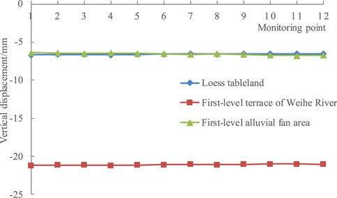
FIGURE 14. Vertical displacement curves under a 24 m tunnel buried depth.
According to the simulation analysis in different regions of Xi’an, the supporting measures such as cushion and bolt play a crucial role in reinforcing the existing pipe gallery when it is subjected to the influence of the excavation of subway tunnel beneath it. For this reason, the lateral displacement of the pipe gallery is quite small, and thus can be ignored. And the pipe gallery is mainly affected by settlement deformation. The major conclusions of this paper are as follows.
(1) When the regional soil quality is relatively stable and the difference of soil parameters is small, the settlement of pipe gallery declines with the rising spacing (buried depth of subway tunnel), such as the loess tableland. When the regional soil quality is unstable and the soil parameters differ significantly, the settlement of pipe gallery is greatly affected by the soil layer where the tunnel is located, such as the first-level terrace of Weihe River and the first-level alluvial fan area.
(2) In the loess tableland area, when the buried depth of subway tunnel is greater than 12 m, the settlement deformation of the existing pipe gallery does not exceed the allowable limit of 10 mm, which meets the deformation criterion. In the first-level terrace of Weihe River, when the tunnel depth is less than or equal to 24 m, the deformation criterion is not met. In the first-level alluvial fan area, when the tunnel burial depth is 12 m and 24 m, the deformation criterion is met; whereas when the tunnel burial depth is 18 m, the settlement deformation of the existing pipe gallery exceeds the allowable limit of 10 mm, so the deformation criterion is not met.
Therefore, to reduce the disturbance of tunnel excavation to the existing pipe gallery, the influence of soil parameters and the spacing between the tunnel and the pipe gallery should be considered first. In addition, various supporting methods such as soil layer grouting (to improve the soil properties) and cushion can also be considered.
The original contributions presented in the study are included in the article/Supplementary Material, further inquiries can be directed to the corresponding author.
SW: Project administration, methodology, modeling, formal analysis, visualization, writing - original draft; HZ: Project administration, methodology, formal analysis, writing—review and Editing; YM: Methodology, formal analysis, writing—original draft; LN: Methodology, formal analysis, writing—original draft; TT: Modeling, visualization, writing—original draft.
This work was supported by Shaanxi Provincial Key Research and Development Project (2021SF2-02), the Public Welfare Geology Special Project of Shaanxi Province (202109, 20180303).
The authors declare that the research was conducted in the absence of any commercial or financial relationships that could be construed as a potential conflict of interest.
All claims expressed in this article are solely those of the authors and do not necessarily represent those of their affiliated organizations, or those of the publisher, the editors and the reviewers. Any product that may be evaluated in this article, or claim that may be made by its manufacturer, is not guaranteed or endorsed by the publisher.
Chen, R. P., Tang, L. J., Ling, D. S., and Chen, Y. M. (2011b). Face stability analysis of shallow shield tunnels in dry sandy ground using the discrete element method. Geotech. 38 (2), 187–195. doi:10.1016/j.compgeo.2010.11.003
Chen, R. P., Zhu, J., Liu, W., and Tang, X. W. (2011a). Ground movement induced by parallel epb tunnels in silty soils. Tunn. Undergr. Space Technol. 1 (26), 163–171. doi:10.1016/j.tust.2010.09.004
Dashti, S., Hashash, Y., Gillis, K., Musgrove, M., and Walker, M. (2016). Development of dynamic centrifuge models of underground structures near tall buildings. Soil Dyn. Earthq. Eng. 86, 89–105. doi:10.1016/j.soildyn.2016.04.014
Duan, Xu, Dong, Qi, Ye, Wanjun, Men, Yuming, and Zhang, Chang yi (2020). Study on utility tunnel’s strained condition crossing the transition zone of loess high embankment. Chin. J. Undergr. Space Eng. (5): 1529–1537 + 1579.
Feng, Tianwei, Lü, Baowei, Li, Jingmei, and Li, Dechang (2018). Study on the influence of open-cut construction of utility tunnels on adjacent subway tunnel. Mod. Tunn. Technol. 55 (S2), 1116–1121. doi:10.13807/j.cnki.mtt.2018.S2.143
Gao, Kai, and Haifeng, S. I. (2018). The impact of utility pipe tunnel on the overhead existing subway tunnel. Cuangzhou Archit. (4), 32–36.
Hu, Xiang, and Xue, Weichen (2010). Experimental study on mechanical performance of prefabricated prestressed composite pipe rack. J. Civ. Eng. 43 (5), 29–37. doi:10.15951/j.tmgcxb.2010.05.017
Hu, Zhiping, Zhang, Dan, and Zhang, Yaguo (2019). Test study on deformation and failure mechanisms of utility tunnels obliquely crossing ground fissures. Chin. J. Rock Mech. Eng. 38 (12), 2550–2560. doi:10.13722/j.cnki.jrme.2019.0308
Kimura, H., Itoh, T., Iwata, M., and Fujimato, K. (2005). Application of new urban tunneling method in baikoh tunnel excavation. Tunneling Undergr. Space Technol. 20 (20), 151–158. doi:10.1016/j.tust.2003.11.007
Li, Jie, Yue, Qingxia, and Chen, Juan (2009). Research on shaking-table test and finite element numerical simulation of utility tunnel. Earthq. Eng. Eng. Dyn. 29 (4), 41–45. doi:10.13197/j.eeev.2009.04.016
Li, Z. Q., Lai, J. X., Ren, Z. D., Shi, Y., and Kong, X. (2023). Failure mechanical behaviors and prevention methods of shaft lining in China. Eng. Fail. Anal. Vol. 143, 106904. Article ID 106904. doi:10.1016/j.engfailanal.2022.106904
Liu, Naifei, Ning, Li, Li, Guofeng, Song, Zhanping, and Wang, Shuangjie (2022a). Method for evaluating the equivalent thermal conductivity of a freezing rock mass containing systematic fractures. Rock Mech. Rock Eng. 2022, 7333. doi:10.1007/s00603-022-03038-9
Liu, Naifei, Ning, Li, Wang, Shuangjie, Li, Guofeng, and Song, Zhanping (2022b2023). A fully coupled thermo-hydro-mechanical model for fractured rock masses in cold regions. Cold Regions Sci. Technol. 205, 103707. doi:10.1016/j.coldregions.2022.103707
Luo, Tao (2013). Rayleigh wave research based on wavelet transform and response of the utility tunnel. Shandong: Shandong Jianzhu University.
Ma, Huiyong, Zhang, Liang, Zhang, Yutong, Mei, Yuan, and Zhao, Jiabing (2019). Ground cracking impact on utility tunnel stress properties under multiple working conditions. J. Munic. Technol. 37 (05), 206–209.
Ma, S., Shao, Y., Liu, Y., Jiang, J., and Fan, X. L. (2017). Responses of pipeline to side-by-side twin tunnelling at different depths: 3d centrifuge tests and numerical modelling. Tunn. Undergr. Space Technol. 66, 157–173. doi:10.1016/j.tust.2017.04.006
Ministry of Housing and Urban-Rural Development of the People's Republic of China (2011). GB50007-2011 Code for design of building foundation. Beijing: China Architecture and Building Press.
Ministry of Housing and Urban-Rural Development of the People's Republic of China (2015). GB50010-2010 Code for design of concrete structures. Beijing: China Architecture and Building Press.
Ministry of Housing and Urban-Rural Development of the People's Republic of China (2013). GB50911-2013 Urban rail transit engineering monitoring technical specification. Beijing: China Architecture and Building Press.
Peng, Shixing. (2017). Consideration on the technical feasibility of the simultaneous construction of the utility tunnel and subway. Fujian Archit. Constr. (7), 164–166.
Qin, Y. W., Lai, J. X., Yang, T., Zan, W. B., Feng, Z. H., Liu, T., et al. (2022). Failure analysis and countermeasures of a tunnel constructed in loose granular stratum by shallow tunnelling method. Eng. Fail. Anal. 141, 106667. doi:10.1016/j.engfailanal.2022.106667
Shamsabadi, A., Law, H., and Amini, M. (2002). “Seismic rock-tunnel-structure interaction analysis,” in Elsevier Science Ltd:12th European Conference on Earthquake Engineering, Oxford, 9-13 September 2002 (Oxford: Elsevier), 1–8.
Shamsabadi, A., Sedarat, H., and Kozak, A. (2001). Seismic soil tunnel structure interaction analysis of the posey webster street tunnels. Oxford: Ustapan Soil-Structure-Interaction Workshop, 1–21.
Shi, Xiaojun, Chen, Juan, and Li, Jie (2010). Shaking table test on utility tunnel under non-uniform seismic excitations(Ⅰ): Experimental setup. Earthq. Eng. Eng. Dyn. 30 (1), 45–52.
Tang, Aiping, Li, Zhiqiang, Feng, Ruicheng, and Zhou, Xiyuan (2009). Model experiment and analysis on seismic response of utility tunnel systems using a shaking table. J. Harbin Inst. Technol. (6), 1–5.
Wang, Li, and Jiang, Shichao (2019). Research on the construction scheme of utility tunnel above-crossing existing subway. Chin. J. Undergr. Space Eng. 15 (S2), 717–723.
Wu, Yuhai (2017). Numerical simulation of influence of the underground construction of the utility tunnel to underneath shield tunnel. Constr. Technol. (17), 105–109. doi:10.7672/sgjs2017170105
Yang, Min, Li, Hongru, Ning, Li, and Yang, Shun (2020). Effect of subway excavation with different support pressures on existing utility tunnel in xi’an loess. Adv. Civ. Eng. 2020, 1–14. doi:10.1155/2020/8818949
Yang, Min, Li, Hongru, Ning, Li, and Yang, Shun (2021). Influence of utility tunnel on the lower part of the existing double-track shield tunnel in loess soil. Adv. Mater. Sci. Eng. 2021, 1–13. doi:10.1155/2021/9927245
Yang, Youbin, Li, Huapei, and Tong, Lin (2019). Study on the influence of adjacent construction of integrated pipe gallery foundation pits on existing subway tunnels. Chin. J. Undergr. Space Eng. 15 (S1), 188–194.
Ye, Fei. (2014). Seismic response analysis of pipe-utility tunnel structural system. China: Institute of Engineering Mechanics.
You, Haoyu. (2011). Seismic isolation analysis on pipeline in utility tunnel. China: Harbin Institute of Technology.
You, Xinhua. (2017). Present status and future development trend of urban utility tunnel construction. Urban Archit. Space 24 (3), 6–9.
Zhang, Yuwei, Fan, Shengyuan, Yang, Donghui, and Zhou, Fei (2022b). Investigation about variation law of frost heave force of seasonal cold region tunnels: A case study. Front. Earth Sci. 9, 806843. doi:10.3389/feart.2021.806843
Zhang, Yuwei, Song, Zhanping, and Weng, Xiaolin (2022a). A constitutive model for loess considering the characteristics of structurality and anisotropy. Soil Mech. Found. Eng. 59 (1), 32. doi:10.1007/s11204-022-09781-z
Zhao, Yongjian, Gong, Yi, Ding, Yong, and Dong, Xuehua (2018). Effect of explosion in a gas pipeline compartment of a utility tunnel on neighboring Metro tunnels. Mod. Tunn. Technol. 55 (06), 139–143. doi:10.13807/j.cnki.mtt.2018.06.019
Zhu, Caihui, Li, Ning, Liu, Houxiang, and Zhang, Zhiqiang (2011). Analysis of ground settlement induced by workmanship of shield tunnelling. Rock Soil Mech. 32 (01), 158–164. doi:10.16285/j.rsm.2011.01.019
Zhu, Caihui, Ning, Li, and Zhang, Zhiqiang (2010a). Analysis and prediction of land subsidence induced by shield construction in loess strata in Xi'an. Chin. J. Geotechnical Eng. 32 (07), 1087–1095.
Zhu, Caihui, Ning, Li, and Zhang, Zhiqiang (2010b). Analysis and prediction of land subsidence induced by shield construction in loess strata in Xi'an. Chin. J. Geotechnical Eng. 32 (07), 1087–1095.
Keywords: geological characteristics, shield tunnel, construction disturbance, utility tunnel, deformation
Citation: Wei S, Zenglin H, Min Y, Ning L and Tianxiang T (2023) Impact of subway shield tunnel construction on deformation of existing utility tunnel. Front. Earth Sci. 11:1104865. doi: 10.3389/feart.2023.1104865
Received: 22 November 2022; Accepted: 24 January 2023;
Published: 15 February 2023.
Edited by:
Yuwei Zhang, Xi’an University of Architecture and Technology, ChinaCopyright © 2023 Wei, Zenglin, Min, Ning and Tianxiang. This is an open-access article distributed under the terms of the Creative Commons Attribution License (CC BY). The use, distribution or reproduction in other forums is permitted, provided the original author(s) and the copyright owner(s) are credited and that the original publication in this journal is cited, in accordance with accepted academic practice. No use, distribution or reproduction is permitted which does not comply with these terms.
*Correspondence: Hong Zenglin, bGhxaHpsQDE2My5jb20=
Disclaimer: All claims expressed in this article are solely those of the authors and do not necessarily represent those of their affiliated organizations, or those of the publisher, the editors and the reviewers. Any product that may be evaluated in this article or claim that may be made by its manufacturer is not guaranteed or endorsed by the publisher.
Research integrity at Frontiers
Learn more about the work of our research integrity team to safeguard the quality of each article we publish.