 Shupeng Chai
 Liujun Fan1
- 1Zhengzhou Key Laboratory of Geocomposite Materials, Department of Civil Engineering and Architecture, Zhengzhou University of Science and Technology, Zhengzhou, China
- 2Henan Province Information Consultation Designing Research Co., LTD., Zhengzhou, China
Light poles or transmission towers may become tilted over the design life, which needs rectifying considering safety and continued use. The jacking pushing method is an efficient way to rectify deviations of these inclined structures supported with rigid piles, but there is a lack of relevant engineering standards and research in this aspect. In this study, a numerical method using FLAC3D is proposed to estimate the required jacking force at the pile top to plumb inclined piles in cohesive soils. Good agreements between the results obtained from the present numerical models and those taken from published experimental and numerical results suggest the reliability of the conclusion. Besides, elaborate parameter analyses including pile geometry, soil properties, and properties of the soil-pile interface are conducted to investigate their influences on the required jacking force. The results can contribute to a safer and more cost-efficient design for rectifying deviations of rigid inclined piles, especially in terms of the required jacking force.
Introduction
Inclined structures or buildings are prone to instability problems, which have brought great challenges for civil engineers and researchers. The most straightforward and safest way is to demolish those inclined structures and rebuild them, but sometimes it may be inappropriate for historical and cultural architecture such as the Leaning Tower of Pisa (Burland, 2002; Wen et al., 2020; Zhou et al., 2020). Moreover, it is also unrealistic to rebuild all the inclination structures, especially those induced by human activities like neighboring excavation or filling (Shi et al., 2013; Peng et al., 2021). In these conditions, deviation rectification becomes an alternative option.
The inclination of structures is mainly caused by the differential settlement of nearby soil, which may be related to groundwater movement, soft soil, improper design, or human activities (Zhang et al., 2015; Zhang et al., 2018; Soomro et al., 2020; Wen et al., 2020). For deviation rectification, foundations in the less deformed areas can be lowered by soil excavation (Ovando-Shelley and Santoyo, 2001; Burland, 2002; Liu, 2006), water treatment (Li, 2015), or applying additional pressure (Yang, 2020). While foundations in the areas with a larger displacement can be uplifted by foundation underpinning (Wen et al., 2020), compaction grouting (Wang et al., 2011; Peng et al., 2021), jacking methods (Zhang et al., 2018), etc. For inclined structures like transmission towers or light poles supported with single rigid piles, a horizontal force can also be applied by anchor pulling or jack pushing in opposition to the inclined direction for deviation rectification (Peng, 2017). Among the abovementioned methods, the jacking pushing method is the most efficient way of rectifying inclined piles. Nevertheless, there is still no standard procedure for deviation rectification of inclined structures supported with piles. Results published on this topic are also rare.
Relevant studies on the lateral responses of batter piles can serve as a reference for deviation rectification (Zhang et al., 1999; Hazzar et al., 2017; Kim et al., 2021; Liang et al., 2022). Zhang et al. (1999) conducted centrifuge tests for square batter piles laterally loaded in sandy soils. They reported that the lateral load decreased with increasing pile inclination angle when the load was applied in the opposite direction to pile inclination. The same conclusion have also been drawn by several researchers based on numerical or theoretical analyses of batter piles in sandy soils (Rajashree and Sitharam, 2001; Hazzar et al., 2017; Ashour et al., 2020). Whereas Hazzar et al. (2017) presented a different phenomenon obtained from FLAC3D that the lateral load would increase with increasing pile inclination angle in cohesive soils when the load was applied against the inclined direction of piles. Besides, the machine learning technique (Bai et al., 2021) has also been widely applied to predict lateral pile bearing capacity (Das and Basudhar, 2006; Muduli et al., 2013).
However, none of the existing publications has concentrated on deviation rectification of those batter piles, as those piles are built inclined from the beginning for a large lateral resistance. Whereas for the pile inclined during use, it is required to rectify the deviation to ensure the continued use of the building on it. Furthermore, existing studies on lateral responses of batter piles mainly focus on the evaluation of lateral bearing capacity (Zhang et al., 1999; Hazzar et al., 2017). While for the deviation rectification of inclined piles, the required jacking force at the pile top to return the inclined piles to vertical conditions is critical to guide the rectification design but has hardly been investigated in detail.
In this study, the lateral responses of rigid inclined piles in cohesive soils will be first investigated numerically with FLAC3D. Then, a method of estimating the required jacking force will be described in detail when using the jacking pushing method for deviation rectification. Finally, the required jacking force will be analyzed and discussed by considering different pile and soil parameters.
Finite-difference model
The three-dimensional (3D) finite-difference numerical software FLAC3D is employed to estimate the required jacking force P (kN) for deviation rectification of rigid batter piles (Itasca., 2013). It has been widely used in solving geotechnical and mining problems (Hazzar et al., 2017; Chai, 2020; Chai, 2022).
Model details
Figure 1A shows a cross section of a typical physical model for deviation rectification of an inclined pile. The pile is previously built to support a 20-m-high light pole. The vertical load FV (kN) and horizontal load FH (kN) at the pile top are calculated at 36 and 26.2 kN, respectively. α (°) is the inclination angle of the pile foundation. D (m) and L (m) are the diameter and the length of the inclined pile, respectively. During the rectification process, a constant velocity v (m/s) is applied at the top of the inclined pile until the pile becomes vertical.
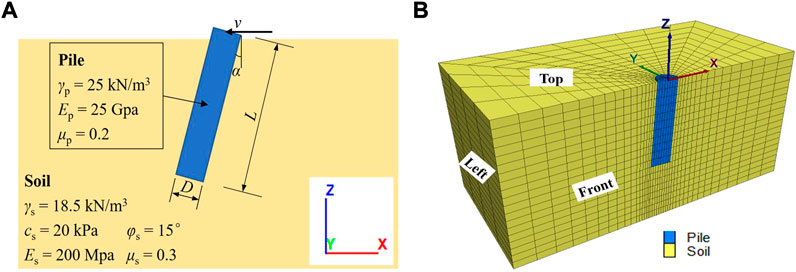
FIGURE 1. A typical model for deviation rectification of rigid inclined piles: (A) physical and (B) numerical model.
Considering the model symmetry and computing efficiency, a numerical model shown in Figure 1B with only half of the real geometry is constructed with FLAC3D. For the reference case, the pile inclination angle α is 3°. The pile diameter D is 1.4 m, and the pile length L is 6.0 m with 5.9 m embedded in the soil. A linear-elastic material is considered for the pile, which is characterized by γp = 25 kN/m3 (unit weight), Ep = 25 GPa (Young’s modulus), and μp = 0.2 (Poisson’s ratio). While the surrounding soil is considered elastoplastic obeying the Mohr-Coulomb criterion with a unit weight γs of 18.5 kN/m3, a cohesion cs of 20 kPa, an internal friction angle φs of 15°, Young’s modulus Es of 200 MPa, Poisson’s ratio μs of 0.3, and a dilation angle ψs of 0°. All the parameters used in this study are either obtained in engineering practice or taken from published results (Itasca 2013; Peng 2017; Wen et al., 2020).
The axis of symmetry (the front boundary shown in Figure 1B) is fixed in the y-direction. The other three lateral boundaries (namely, the left, the right, and the back boundary) of the model keep fixed in x and y-directions. The displacements in all directions at the base are prohibited while the top surface can move freely. The mesh size and domain geometry are both determined after detailed sensitivity analyses with numerous trial numerical simulations. A uniform element size of 0.5 m is selected in the vertical direction while a radial mesh around the pile is applied in the horizontal direction. The domain geometry, the horizontal distance from the pile edge to the model edge, is 10 m for the reference case.
Interface elements are simulated between the pile and surrounding soil. In the reference case, the cohesion (ci, kPa) and the internal friction angle (φi, °) of the interface elements are considered equal to cs and φs, respectively. The normal (kn, GPa/m) and shear (ks, GPa/m) stiffnesses of the interface elements are 5.38 GPa/m, which is calculated according to the FLAC3D manual (Itasca., 2013).
Modeling procedures
The deviation rectification of inclined piles is simulated by the following four steps:
(1) Simulation of initial equilibrium state. In this step, the pile zones are assigned the same material properties as the soil.
(2) Installation of the pile. The actual material properties are assigned to the pile zones and the model is then brought to an equilibrium state.
(3) Application of loads. The vertical load FV and horizontal load FH are added at the top of the pile foundation in the numerical model before running to equilibrium again.
(4) Deviation rectification of inclined piles. After setting the displacements to zero, a constant velocity v of -5×10⁻⁷ m/s in the x-direction is applied at the pile top, which is also determined by sensitivity analyses. The displacement at the pile top and pile bottom as well as the horizontal force at the pile top are monitored throughout the rectification process. The simulation stops once the pile becomes vertical.
Model configuration
To investigate the required jacking force P for deviation rectification of rigid inclined piles, a series of numerical simulations shown in Table 1 are conducted with FLAC3D. The reference case (Case 0 in Table 1) is used to show the modeling procedures and how to obtain the required jacking force for deviation rectification of rigid inclined piles in detail. Cases V1, V2, and V3 are taken from the literature and performed to validate the numerical results. The remaining cases (Cases 1–10 in Table 1) are conducted to investigate the factors which may influence the required jacking force, for instance, the pile geometry (Cases 1–3), soil properties (Cases 4–8), and interface properties (Cases 9–10).
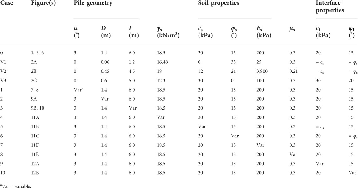
TABLE 1. A detailed program of numerical simulations (with γp = 25 kN/m3, Ep = 25 GPa, μp = 0.2, and ψs = 0°).
Validation of the numerical simulations
The numerical software FLAC3D is first verified with classic analytical solutions to solve cylindrical hole problems, showing good consistency, with detailed comparisons shown in Chai (2020). To further verify the reliability of the numerical results in the present study, numerical simulations (Cases V1, V2, and V3) are conducted to compare with experimental results carried out by Zhang et al. (2021) and Wang (2015) and numerical results given in FLAC3D Manual (Itasca., 2013).
Zhang et al. (2021) carried out model tests to investigate the horizontal bearing behavior of piles in a model box that is 1.5 m long, 1.0 m wide, and 1.5 m high. The studied pile is 1.2 m in length with 1.0 m embedded in the sand. Other parameters are the same as Case V1 in Table 1. No vertical load (or FV = 0) is applied at the pile top. The variations of the horizontal force p with different horizontal displacements s measured by Zhang et al. (2021) and obtained from numerical simulations are compared in Figure 2A. The numerical results of Case V1 are observed to agree well with the experimental results of Zhang et al. (2021).
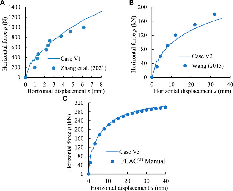
FIGURE 2. Comparisons between the numerical results obtained in the present study with experimental results of (A) Zhang et al. (2021) and (B) Wang (2015), and (C) numerical results in FLAC3D Manual.
Besides, the experiment results performed by Wang (2015) for the lateral response of a rigid pile in cohesive soil are also taken for validation. The studied pile is 4.5 m in length with 4.0 m embedded in the soil, and other parameters are given in Table 1 (Case V2). As shown in Figure 2B, the present numerical results correspond well with the experiment results, suggesting the reliability of the numerical models used in this study.
Case V3 is a numerical case taken from FLAC3D Manual for the axial and lateral loading of a vertical pile (Itasca., 2013). A vertical load of 100 kN is applied at the pile top before applying the horizontal velocity. Figure 2C illustrates the comparisons of the horizontal forces p under different horizontal displacements s obtained from the numerical simulations. The numerical results correspond well with those shown in FLAC3D Manual.
It can be concluded from Figure 2 that the numerical models and modeling procedures described in the present study are capable of investigating the pile responses. The good agreements of the numerical results in the present study with experimental and numerical results in the literature suggest the validity and reliability of numerical results.
Numerical results and discussion
Reference case (Case 0)
Figure 3 shows the contour of x-displacement for the reference case during pile deviation rectification. The top of the rigid batter pile moves left while the bottom moves right. The pile can be considered to be rectified when the relative x-displacement xr (m) between the pile top and pile bottom is equal to the offset distance xo (m) due to pile inclination. The corresponding horizontal force at the pile top is the required jacking force P for the deviation rectification of inclined piles. For instance, the offset distance xo in the x-direction in Case 0 is
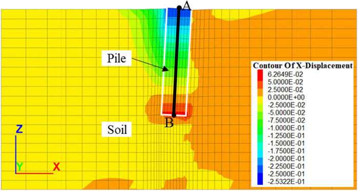
FIGURE 3. Contour of x-displacement for the reference case.
The relative x-displacement xr can be calculated by adding together the absolute value of x-displacement xt (m) at the center of pile top (Point A in Figure 3) and that xb (m) at the center of pile bottom (Point B in Figure 3). In addition, x-displacement along the pile center (Line AB) shown in Figure 3 is also monitored to analyze the pile response.
Figure 4 shows the x-displacements monitored at Points A and B and Line AB. In Figure 4A, absolute values of the x-displacements of Points A (xt) and B (xb) are used. Both xt and xb increase linearly with increasing calculation steps. The offset distance xo (= 0.314 m) and relative displacement xr between Points A and B are also calculated and plotted together, which can help judge whether the deviation rectification procedure has been completed. Figure 4B presents the x-displacements along Line AB at different stages of the deviation rectification procedure. The x-displacement is observed to vary linearly along the pile length in any stage. The x-displacement at a distance dr (m) of about 5.03 m from the pile top remains 0, suggesting that the pile rotates counterclockwise around the position. Furthermore, the zone state for the reference case after deviation rectification is presented in Figure 5. Together with the results shown in Figure 3, it suggests that no obvious pile failure occurs during the deviation rectification process.
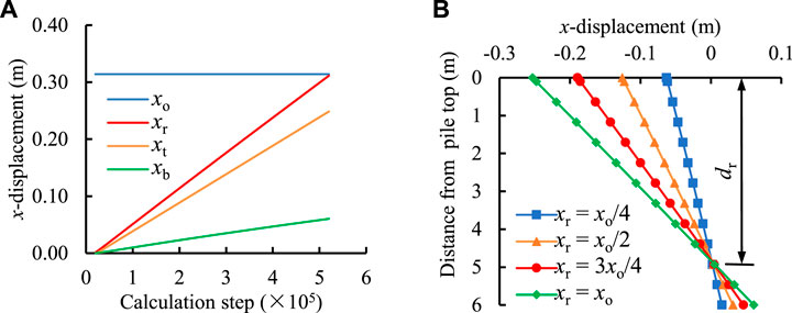
FIGURE 4. Variation of x-displacement (A) as a function of calculation steps and (B) along Line AB.
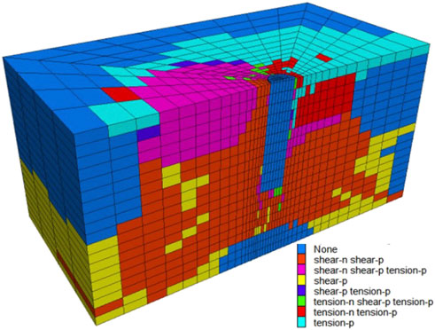
FIGURE 5. Zone state for the reference case after deviation rectification.
Figure 6 shows the variation of horizontal force p with the horizontal displacement s at the pile top for the reference case. The horizontal force has been doubled considering the symmetry of the numerical model. P increases with the increase of s, but the growth rate becomes smaller and smaller, the trend of which agrees well with previous experimental and numerical results (Hazzar et al., 2017; Li et al., 2018; Zhang et al., 2021). As shown in Figure 6, when xr = xo/4, xo/2, 3xo/4, and xo, the horizontal forces are 1,168 kN, 1,294, 1,374, and 1,441 kN, respectively. The required jacking force P is 1,441 kN for the reference case.
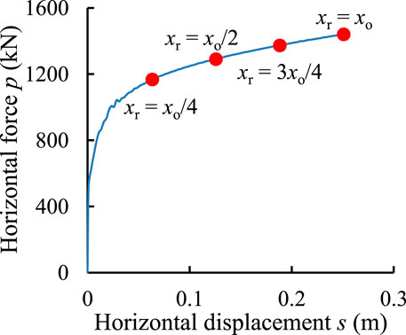
FIGURE 6. Variation of horizontal force p with horizontal displacement s at the pile top for Case 0.
Effect of pile geometry
Figure 7 shows the effect of pile inclination angle α on the required jacking force P as α increases from 1° to 5°. The variation of horizontal force p with the horizontal displacement s at the pile top is plotted in Figure 7A. It indicates that p increases with α at the same s, agreeing well with the pile responses in clayey soils reported by Hazzar et al. (2017). It may be partially due to the higher passive Earth pressure applied on the left of inclined piles caused by a larger inclination angle. The position when the pile becomes vertical is marked in Figure 7A, and the required jacking force P with the variation of pile inclination angle α is plotted in Figure 7B. It indicates that P increases by 80% from 1,180 to 2,129 kN as pile inclination angle α increases from 1° to 5°.
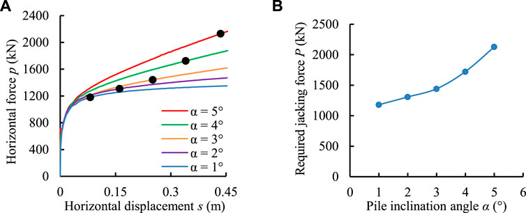
FIGURE 7. The effect of pile inclination angle α on the required horizontal force P (Case 1): (A) Variation of horizontal force p with horizontal displacement s at the pile top with different pile inclination angles α and (B) Variation of the required horizontal force P with α.
For all the five cases when pile inclination angle α varies, the pile rotates around a point throughout the rectification procedure. The variation of horizontal displacement along Line AB after deviation rectification is presented in Figure 8. It indicates a linear variation of the x-displacement along the pile. The rotating point of the pile decreases slightly from 5.13 to 4.83 m away from the pile top as α increases from 1° to 5°.
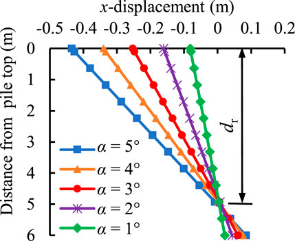
FIGURE 8. Variation of x-displacement along the pile (Line AB) after the deviation rectification of inclined piles at different values of pile inclination angle α.
The influences of other parameters regarding pile geometry including pile diameter D (Case 2) and pile length L (Case 3) on the required horizontal force P are portrayed in Figure 9. One can see from Figure 9A an increase in P from 903 to 2,186 kN as D increases from 0.8 to 2.0 m. As shown in Figure 9B, an increase in L from 4.5 to 7.5 m also causes the increase of P from 1110 to 1966 kN. The tendency is straightforward as the increasing contact area due to increasing D or L contributes to a larger P.
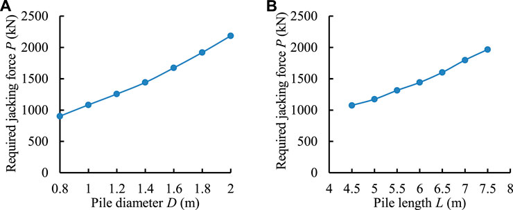
FIGURE 9. Variations of the required horizontal force P with pile geometry: (A) Pile diameter D (Case 2) and (B) pile length L (Case 3)
Besides, a linear variation of x-displacement along the pile and a rotation of the pile can also be observed for Cases 2 and 3. The position of the rotating point is nearly insensitive to the variation of pile diameter D, and the distance dr between the point and pile top remains around 5.03 m. Figure 10 illustrates the horizontal displacement along Line AB after deviation rectification for cases with different values of pile length L. With an increase of L from 4.5 to 7.5 m, the rotating point of the pile increases from 3.69 to 6.37 m away from the pile top. It is worth mentioning that the ratio of dr over L stays almost unchanged at about 0.84.
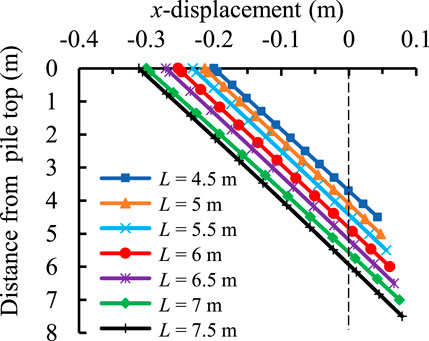
FIGURE 10. Variation of x-displacement along the pile (Line AB) after the deviation rectification of inclined piles at different values of pile length L.
Effect of soil properties
Figure 11 presents the effects of surrounding soil properties, including unit weight γs (Case 4), cohesion cs (Case 5), internal friction angle φs (Case 6), Young’s modulus Es (Case 7), and Poisson’s ratio μs (Case 8), on the required horizontal force P for deviation rectification of rigid inclined piles.
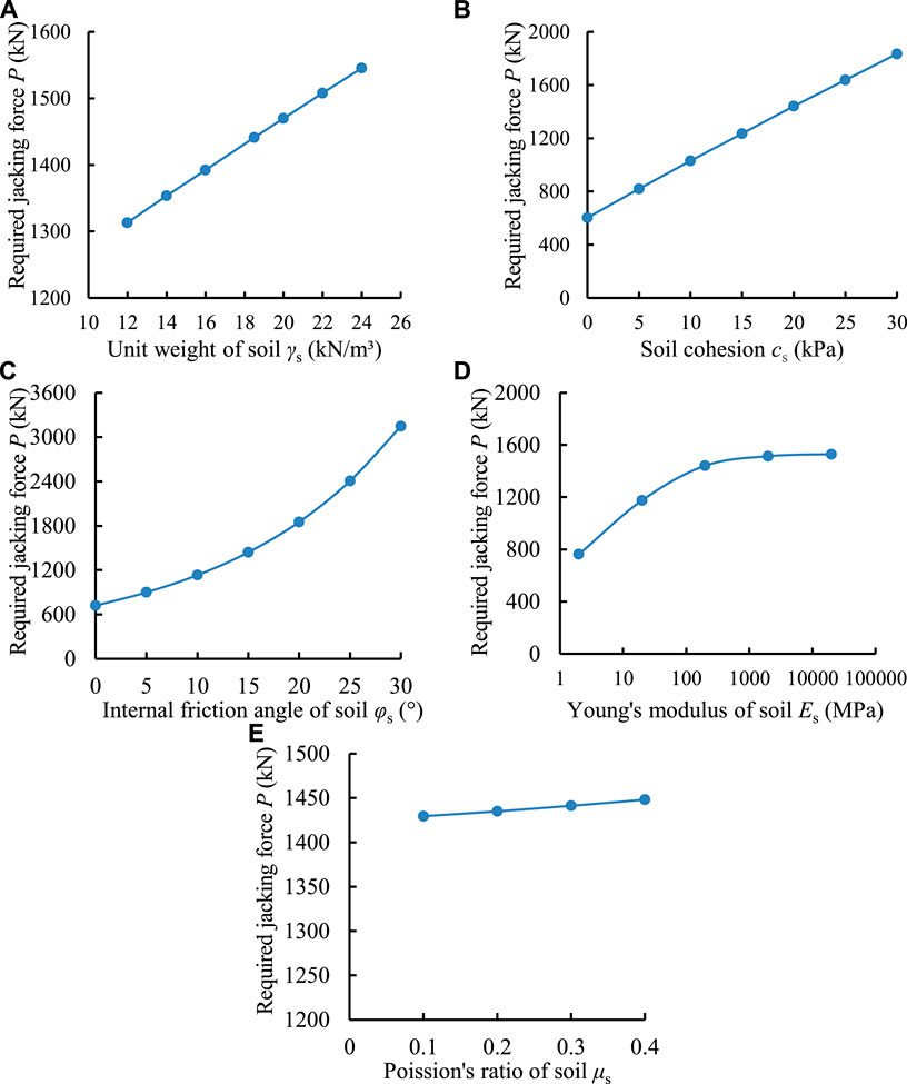
FIGURE 11. Variations of the required horizontal force P with soil properties: (A) Unit weight of soil γs (Case 4), (B) soil cohesion cs (Case 5), (C) internal friction angle of soil φs (Case 6), (D) Young’s modulus of soil Es (Case 7) and (E) Poisson’s ratio of soil μs (Case 8)
Figure 11A shows the required horizontal force P at the pile top is 1,313 kN when γs = 12 kN/m³ while it increases linearly to 1,545 kN when γs = 24 kN/m³. It can be attributed to the increased passive Earth pressure at the left of the inclined pile. Figures 11B,C illustrate the influences of shear strength parameters of the surrounding soil on the required horizontal force P for deviation rectification. P increases linearly from 603 kN for cohesionless soil to 1835 kN for cohesive soil with cs = 30 kPa. Besides, a larger internal friction angle φs of the soil will also lead to a higher jacking force required for deviation rectification. For example, P is 720 kN as φs = 0, while it increases exponentially to 3,146 kN as φs = 30°. Deformation is observed in the surrounding soils during the deviation rectification procedure, especially in the soil near the left of the inclined pile, as shown in Figure 3. It suggests the failure of soils. Therefore, the higher shear strength of the surrounding soil can contribute to a more stable soil but is unbeneficial to the deviation rectification of inclined piles.
The variation of required horizontal force P with different values of Young’s modulus Es of soil is shown in Figure 11D. When Es is relatively small ranging from 2 to 200 MPa, P increases obviously from 763 to 1,441 kN. Whereas, as Es continues to increase from 200 to 20,000 MPa, P is observed nearly insensitive to the variation of Es. It is partially because the soil with lower stiffness is prone to deformation, thus causing the stress easily released and reducing P. However, once the stiffness of the surrounding soil is large enough (e.g., Es > 200 MPa for Case 7), the shear behavior of the soil may be dominant when considering deviation rectification. Besides, Figure 11E presents the effect of Poisson’s ratio of soil μs on P. It is observed that P slightly increases from 1,429 to 1,448 kN as μs varies between 0.1 and 0.4.
Moreover, the pile is observed to rotate around a position in Cases 4–8 when the material properties vary. With the variation of soil properties, the distance dr between the rotating point and the pile top keeps almost unchanged at about 5.0 m. It is probably because of the consideration of uniform soil in this study, and more efforts are required in this aspect to consider more complex soil properties (Wen et al., 2020; Peng et al., 2021; Xue et al., 2021).
Effect of interface properties
Figure 12 shows the effects of shear properties of the soil-pile interface (Cases 9 and 10) on the required jacking force P for deviation rectification of rigid inclined piles. The variations of P with soil shear properties are also plotted together for comparison. As shown in Figure 12A, P is 1,366 kN when the interface cohesion ci = 0 and increases by 5% to 1,441 kN as ci = 20 kPa. One can also see from Figure 12B an increase of P from 1225 to 1436 kN when the internal friction angle φi of the soil-pile interface varies from 0 to 15°. It is straightforward as the increased shear resistance causes the required jacking force to increase. The trends can be partially verified by Jiang et al. (2022) who found that the horizontal bearing capacity increased with the increase of the internal friction angle of the pile-soil interface.
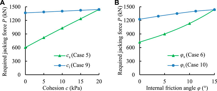
FIGURE 12. Variations of the required horizontal force P with the shear properties of soil-pile interface and soil: (A) Cohesion c (Cases 5 and 9) and (B) internal friction angle φ (Cases 6 and 10).
Figure 12A also indicates that the effect of interface cohesion on the required jacking force can be nearly regarded as negligible compared to the effect of soil cohesion. Similarly in Figure 12B, the required jacking force is observed more sensitive to the variation of internal friction angle φc of soil rather than the internal friction angle φi of the soil-pile interface. The results are valuable if the engineers intend to reduce the required jacking force, and additional work on this aspect is still ongoing.
Conclusion
The study estimates the required jacking force for deviation rectification of rigid inclined piles in cohesive soils with FLAC3D. Factors of influence including the pile geometry, soil properties, and interface shear properties are analyzed numerically.
By comparing the numerical results with previous experimental and numerical results, the proposed modeling procedure is proved to perform well in estimating the required jacking force. The numerical results indicate that the required jacking force increases with increasing pile geometry parameters including pile inclination angle α, pile diameter D, and pile length L. An increasing unit weight γs of the surrounding soil can also contribute to the increase in the required jacking force due to a higher passive Earth pressure acting on the pile. Besides, larger shear strength parameters of the soil including cohesion cs and internal friction angle φs can enhance the soil stability, thus causing the required jacking force to increase. Young’s modulus Es of the soil has a positive effect in increasing the required jacking force when Es is below a critical value (e.g., 200 MPa for Case 7 in this study) but becomes negligible once Es exceeds the value. Moreover, increasing Poisson’s ratio μs of the soil can help increase the required jacking force slightly but seems insignificant compared with the aforementioned parameters. Higher interface shear strength parameters (ci and φi) can increase the required jacking force, but their effects are not pronounced compared with soil shear strength parameters (cs and φs).
The results will be beneficial to estimate the required jacking force for deviation rectification of rigid inclined piles, which contributes to a safer and more cost-efficient design for deviation rectification.
Data availability statement
The original contributions presented in the study are included in the article/supplementary material, further inquiries can be directed to the corresponding author.
Author contributions
SC and LF conceived and designed the study; SC conducted numerical simulations, analyzed the results, and wrote the original draft. LF and HL reviewed the original draft. All authors contributed to the manuscript revision and approved the submitted version.
Funding
This study was financially supported by the Key Scientific Research Project of Higher Education Institutions of the Education Department of Henan Province (grant number 22B560018), and the Science and Technology Research Plan of Henan Province (grant number 222102320404).
Conflict of interest
Author HL is employed by Henan Province Information Consultation Designing Research Co., LTD.
The remaining authors declare that the research was conducted in the absence of any commercial or financial relationships that could be construed as a potential conflict of interest.
Publisher’s note
All claims expressed in this article are solely those of the authors and do not necessarily represent those of their affiliated organizations, or those of the publisher, the editors and the reviewers. Any product that may be evaluated in this article, or claim that may be made by its manufacturer, is not guaranteed or endorsed by the publisher.
References
Ashour, M., Alaaeldin, A., and Arab, M. G. (2020). Laterally loaded battered piles in sandy soils. J. Geotech. Geoenviron. Eng. 146, 06019017. doi:10.1061/(ASCE)GT.1943-5606.0002186
Bai, X.-D., Cheng, W.-C., and Li, G. (2021). A comparative study of different machine learning algorithms in predicting EPB shield behaviour: A case study at the xi’an metro, China. Acta Geotech. 16, 4061–4080. doi:10.1007/s11440-021-01383-7
Burland, J. B. (2002). The stabilization of the leaning tower of Pisa. J. Archit. Conservation 8, 7–23. doi:10.1080/13556207.2002.10785324
Chai, S. (2020). Analytical and numerical studies on the stresses in backfilled stopes and the stability of side-exposed backfill in inclined stopes. Master Thesis.
Chai, S. (2022). Maximum height analysis for mine waste dumps. J. South. Afr. Inst. Min. Metall. In press.
Das, S. K., and Basudhar, P. K. (2006). Undrained lateral load capacity of piles in clay using artificial neural network. Comput. Geotech. 33, 454–459. doi:10.1016/j.compgeo.2006.08.006
Hazzar, L., Hussien, M. N., and Karray, M. (2017). Numerical investigation of the lateral response of battered pile foundations. Int. J. Geotechnical Eng. 11, 376–392. doi:10.1080/19386362.2016.1224030
Itasca, (2013). FLAC3D-Fast Lagrangian analysis of continua in 3 dimensions; user’s guide. Minneapolis, MN: Itasca Consulting Group. version 5.01.
Jiang, J., Fu, C., Chai, W., Zhang, T., and Ou, X. (2022). Analytical solution of lateral bearing capacity of rigid single pile based on modified shaft resisting moment. Chin. J. Rock Mech. Eng., 1–13. doi:10.13722/j.cnki.jrme.2021.1134
Kim, J., Yun, S.-K., Kang, M., and Kang, G. (2021). Behavior characteristics of single batter pile under vertical load. Appl. Sci. (Basel). 11, 4432. doi:10.3390/app11104432
Li, Q. (2015). Research on inclined-rectifying of building with pile foundation. Jordan J. Civ. Eng. 9, 133–138.
Li, Z., Kotronis, P., Escoffier, S., and Tamagnini, C. (2018). A hypoplastic macroelement formulation for single batter piles in sand. Int. J. Numer. Anal. Methods Geomech. 42, 1346–1365. doi:10.1002/nag.2794
Liang, J.-H., Fan, Q.-Y., and Qin, K. (2022). Influence of karst caves on the pile’s bearing characteristics-A numerical study. Front. Earth Sci. (Lausanne). 9. doi:10.3389/feart.2021.754330
Liu, Z. (2006). Fifteen year experience in buildings (structures) rectification and inclination prevention (in Chinese). Soil Engineering and Foundation 20, 108–112.
Muduli, P. K., Das, S. K., and Das, M. R. (2013). Prediction of lateral load capacity of piles using extreme learning machine. Int. J. Geotechnical Eng. 7, 388–394. doi:10.1179/1938636213Z.00000000041
Ovando-Shelley, E., and Santoyo, E. (2001). Underexcavation for leveling buildings in Mexico city: Case of the metropolitan cathedral and the sagrario church. J. Archit. Eng. 7, 61–70. doi:10.1061/(asce)1076-0431(2001)7:3(61)
Peng, C. (2017). The application of dynamic replacement method in deviation rectification of support pile. IOP Conf. Ser. Earth Environ. Sci. 61, 012099. doi:10.1088/1755-1315/61/1/012099
Peng, X., Yang, N., and Zhou, M. (2021). Field tests' study of deviation correction of building near excavation. Adv. Civ. Eng. 2021, 1–10. doi:10.1155/2021/6287388
Rajashree, S. S., and Sitharam, T. G. (2001). Nonlinear finite-element modeling of batter piles under lateral load. J. Geotech. Geoenviron. Eng. 127127, 6047–6612. doi:10.1061/(asce)1090-0241(2001)127:7(604)
Shi, M. L., Zhang, H., and Zhang, R. K. (2013). The inclination of bridge pier due to neighboring embankment construction and its rectification technique. Appl. Mech. Mat. 353-356, 79–83. doi:10.4028/www.scientific.net/amm.353-356.79
Soomro, M. A., Mangi, N., Cheng, W.-C., and Mangnejo, D. A. (2020). The effects of multipropped deep excavation-induced ground movements on adjacent high-rise building founded on piled raft in sand. Adv. Civ. Eng. 2020, 1–12. doi:10.1155/2020/8897507
Wang, H. (2015). The horizontal bearing capacity and numerical simulation study of rigid short pile foundation (in Chinese). Master thesis.
Wang, Y., Wang, X. H., and Zhang, M. (2011). Research on mechanisms and ground uplifting effects by grouting taken the grouting-soil-building interaction into account. Adv. Mat. Res. 163-167, 3488–3498. doi:10.4028/www.scientific.net/amr.163-167.3488
Wen, L., Kong, G., Abuel-Naga, H., Li, Q., and Zhang, Z. (2020). Rectification of tilted transmission tower using micropile underpinning method. J. Perform. Constr. Facil. 34, 04019110. doi:10.1061/(ASCE)CF.1943-5509.0001398
Xue, Z.-F., Cheng, W.-C., Wang, L., and Song, G. (2021). Improvement of the shearing behaviour of loess using recycled straw fiber reinforcement. KSCE J. Civ. Eng. 25, 3319–3335. doi:10.1007/s12205-021-2263-3
Yang, X. (2020). Application of comprehensive rectification method in rectification of buildings. E3S Web Conf. 165, 04004. doi:10.1051/e3sconf/202016504004
Zhang, L., Mcvay, M. C., and Lai, P. W. (1999). Centrifuge modelling of laterally loaded single battered piles in sands. Can. Geotech. J. 36, 1074–1084. doi:10.1139/t99-072
Zhang, X.-L., Xue, J.-Y., Han, Y., and Chen, S.-L. (2021). Model test study on horizontal bearing behavior of pile under existing vertical load. Soil Dyn. Earthq. Eng. 147, 106820. doi:10.1016/j.soildyn.2021.106820
Zhang, X.-N., Shan, R.-L., and Lu, M. (2018). Rectification of jacking method for brick-wooden buildings in deformation analysis with CFST reinforcement. Struct. Des. Tall Spec. Build. 27, e1439. doi:10.1002/tal.1439
Zhang, X.-N., Shi, S.-Y., Wang, X.-L., and Zhao, H.-Y. (2015). Application of comprehensive landing method during the rectification for the brick-concrete buildings in soft soil area. Open Civ. Eng. J. 9, 550–556. doi:10.2174/1874149501509010550
Keywords: deviation rectification, inclined piles, required jacking force, numerical models, pile geometry, soil properties
Citation: Chai S, Fan L and Liang H (2022) Required jacking force for deviation rectification of inclined structures supported with rigid piles. Front. Earth Sci. 10:998798. doi: 10.3389/feart.2022.998798
Received: 20 July 2022; Accepted: 29 August 2022;
Published: 14 September 2022.
Edited by:
Dominic E. L. Ong, Griffith University, AustraliaReviewed by:
Wen-Chieh Cheng, Xi’an University of Architecture and Technology, ChinaDanqing Song, Tsinghua University, China
Copyright © 2022 Chai, Fan and Liang. This is an open-access article distributed under the terms of the Creative Commons Attribution License (CC BY). The use, distribution or reproduction in other forums is permitted, provided the original author(s) and the copyright owner(s) are credited and that the original publication in this journal is cited, in accordance with accepted academic practice. No use, distribution or reproduction is permitted which does not comply with these terms.
*Correspondence: Shupeng Chai, c2h1cGVuZy5jaGFpQG91dGxvb2suY29t