 Yangsheng Ye1
 Peiyong Wei
95% of researchers rate our articles as excellent or good
Learn more about the work of our research integrity team to safeguard the quality of each article we publish.
Find out more
ORIGINAL RESEARCH article
Front. Earth Sci. , 09 January 2023
Sec. Structural Geology and Tectonics
Volume 10 - 2022 | https://doi.org/10.3389/feart.2022.996876
The elastic foundation beam theory has been widely used in civil engineering, including railway, tunnel, and building foundations. With the development of fabricated structures, more elastic foundation beams need to be prestressed. In order to explore the frame foundation beam with the fabricated anchor-cable in the slope reinforcement project, in this article, prestress is applied to both ends of the beam. Then, according to the calculation method of internal force and deformation of the beam under concentrated force and the equivalent load theory of the prestressed structure, three new methods: the finite difference method (FDM) of the Euler–Bernoulli beam on the Winkler foundation, FDM of the Euler–Bernoulli beam on the Pasternak foundation, and theoretical analytical solution of the Timoshenko beam on the Winkler foundation, are deduced to calculate internal force and deformation under prestress force and concentrated force, respectively. Typical calculation parameters are selected for design and verification via the three new methods and GEO5, respectively. The results show that the calculated values of the three new methods are basically consistent with those calculated using GEO5 software, which verifies the feasibility of the three new methods.
The cast-in-suit anchor frame beam was introduced in China in the 1990s by the China Academy of Railway Sciences (CARS). Over the past decades, a relatively complete set of cast-in-suit anchor frame beams has been formed, including design and construction (Wu et al., 2011; Zhang et al., 2022). Moreover, it has been widely employed in slope reinforcement of railway, highway, and water conservancy projects and other infrastructure engineering (Song and Zhou, 2004; Xia and Zhou, 2006; Wu and Huang, 2008; Li et al., 2019) and has acquired good reinforcing effects (Cao et al., 2016; Zhao et al., 2018; Zhao et al., 2021). However, some problems have also been exposed in engineering applications: 1) longer construction periods; 2) instable construction quality and insufficient durability; 3) high labor costs and personnel security issues. Instead, prestressed precast anchor frame beams, with a higher degree of mechanization, a lower risk of steep slope operation, better molding quality, and reinforcing while excavating, become a new direction of slope reinforcement technology.
Compared with the traditional cast-in-suit anchor frame beam, the pre-tensioning method or post-tensioning method is adopted to apply prestress to the prefabricated beam body before applying anchor loads to the prestressed precast anchor frame beam. The design and construction methods of traditional cast-in-suit anchor frame beams are no longer applicable. As a new slope reinforcement technology, the first task for the design and construction of prestressed precast anchor frame beams is how to take the prestressed loads of the beam and anchor cable into consideration in the design calculation and then calculate the internal force and deformation of the beam properly. There are two main types of elastic foundation beam models regarding the elastic foundation. One is the Winkler foundation model, which is assumed to have displacement immediately in the load zone, while no displacement in the unload area. The other is the Pasternak foundation model. In this model, it is assumed that the spring elements connect with one layer that is incompressible and vertical and only appears as transverse shear deformation, resulting in the shearing effect among each spring element in the Winkler elastic foundation model. Two main theories are applied to the beam in the elastic foundation beam model. One is the Euler–Bernoulli beam theory, which ignores transverse shear deformation, and the cross-section of the beam is perpendicular to the central axis before and after deformation. The other is the Timoshenko beam theory, which takes the transverse shear deformation into account. Numerous research results have been gained on the calculation of internal force and deformation of cast-in-suit frame foundation beams with the prestressed anchor-cable under load. The main calculation methods include the upside beam method (Ma et al., 2004), the finite difference method (FDM) (Li et al., 2009) and the finite element method (FEM) (Liu et al., 2004) of the Euler–Bernoulli beam on the Winkler elastic foundation, and the finite element method of the Timoshenko beam on the Winkler elastic foundation (Xia et al., 2010). A large number of field tests (Shi et al., 2019; Ye et al., 2019; Li et al., 2020) and measurements have verified the validity of the elastic foundation beam theory on internal force and deformation of cast-in-suit frame foundation beams with the prestressed anchor-cable.
As a novel slope reinforcement technology, few studies have been conducted on the internal force and deformation of the reinforced concrete beam on an elastic foundation under the influence of anchorage force and beam prestress (Zhu et al., 2004; Qin et al., 2008). Some research institutions have carried out numerical simulation analysis of foundation beams with prefabricated prestressed anchor cables (Liu, 2011; Xiao et al., 2013; Sheng and Lu, 2021) and applied that to engineering practices. Yan et al. (2012) and Wang (2012) studied the stress behavior of precast anchor piers with ANSYS. Zhang et al. (2015) and Yang et al. (2015) successfully employed the self-developed precast anchor pier for landslide treatment. Cheng and Wang, (1997) and Wu and Sun, (1999) described the application of the prefabricated cross beam in the reinforcement of the Three Gorges and Yunnan slopes. Leng and Liao, (2007) studied the numerical analysis and engineering application of the prefabricated cross-shaped laminated plate. It can be seen that most precious studies focused on the engineering applications and complex numerical calculations of the foundation beam with the prefabricated prestressed anchor cable, and little attention has been devoted to the simple and accurate calculation formula of stress and deformation of I-beams decomposed by prefabricated cross beams, which is difficult to be applied to the engineering design.
In this article, the most basic structural unit of the prefabricated frame beam—I-beam is taken as an example. Based on the calculation method of the internal force and deformation of the beam under concentrated force and the equivalent load theory of the prestressed structure, three methods, namely, FDM of the Euler–Bernoulli beam on the Winkler foundation, FDM of the Euler–Bernoulli beam on the Pasternak foundation, and the theoretical analytical solution of the Timoshenko beam on the Winkler foundation, are deduced to calculate the internal force and deformation under prestress and concentrated force, respectively. Finally, the rationality of these three methods is verified by GEO5.
The Winkler foundation is a simple model widely used for decades to account for the surface response of elastic bodies. It assumes that the normal surface displacement on the surface and restoring force per unit area are related linearly and completely locally (Yin, 2000a; Yin, 2000b). The Timoshenko beam theory based on the rigid cross-section assumption considers the influence of shear deformation on the additional deflection of the beam. Taking the effect of double-layer reinforcement, prestressed reinforcement of prefabricated beams, and anchorage force of the anchor cable into consideration, a theoretical model of the Timoshenko beam on the Winkler foundation can be obtained to calculate the internal force and deformation of the prestressed I-beam.
The governing differential equation of the Timoshenko beam can be expressed as
If the displacement of beam
where
The pressure on the beam just presents in the form of not only a point but also an interval. Thus, the pressure on the beam
where
Substituting Eq. 4 into Eq. 1, the governing differential equation of the reinforced Timoshenko beam can be rewritten as
The solution of
When
where
According to
where
According to
where
According to
where
If the prestressed reinforcement is arranged in a straight line, the prestressed load can be equivalent to the bending moment
Combine the governing equation and boundary condition, and the results are as follows:
The aforementioned expressions can be described as follows:
Equations 20–25 can be expressed as the following matrix equation:
Stiffness matrix
The parameters
Compared with the Timoshenko beam model, the Euler–Bernoulli beam model is also based on a rigid cross-section assumption, while the transverse shear deformation is ignored. Taking the effect of double-layer reinforcement, prestressed reinforcement of prefabricated beams, and anchorage force of the anchor cable into consideration, a finite difference method of the Euler–Bernoulli beam on the Winkler foundation can be obtained to calculate the internal force and deformation of the prestressed I-beam.
The beam is discretized by equal segmentation in finite difference calculation, as shown in Figure 1.
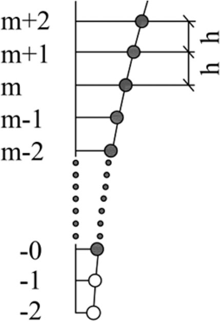
FIGURE 1. Schematic graph of beam discretization.
The subgrade reaction
Therefore, the governing differential equation of the beam on the elastic foundation becomes
where
Equation 30 can be described in terms of the differential form at the arbitrary point (m-point):
where
The difference equation of the bending moment
The difference equation of shear force
Bending moment at the start point (
When shear force at the start point (
When
Substitute Eq. 34 and Eq. 35 into Eq. 36, we get
Then, Eq. 37 can be simplified as follows:
Similarly, assume that the recursion formula at the arbitrary node is
Substituting Eq. 40 into Eq. 31, Eq. (41) can be obtained as follows:
Define
Then, Eq. 41 can be simplified as
Substituting Eq. 34 into Eq. 43, the values of
The extra point at the end point (
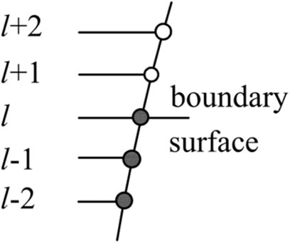
FIGURE 2. Schematic graph of the extra point.
According to the recursion formula, Eqs 47–49 can be obtained as follows:
Let
The displacement of the extra point and end point can be solved as follows:
According to the aforementioned derivation process, the expressions of displacement
The Pasternak foundation was developed on the basis of the Winkler foundation, and it is assumed that there is shear action between spring elements. Taking the effect of double-layer reinforcement, prestressed reinforcement of prefabricated beams, and anchorage force of the anchor cable into consideration, a finite difference method of the Euler-Bernoulli beam on the Pasternak foundation can be obtained to calculate the internal force and deformation of the prestressed I-beam.
The governing differential equation of the beam on the elastic foundation is shown in Eq. 54:
Equation 52 can be described in terms of the differential form, and thus the differential equation at the arbitrary point (m point) is
The derivation process in the Pasternak model is similar to that in the Winkler model, and the displacement
In order to compare and verify the reasonableness of the aforementioned three methods (theoretical model of the Timoshenko beam on the Winkler foundation, FDM of the Euler–Bernoulli beam on the Winkler foundation, and FDM of the Euler–Bernoulli beam on the Pasternak foundation), these three methods were employed to calculate the internal force and deformation of an example of the I-beam applied to an application. In the soft rock slope reinforcement in the Mengping highway project, I-beams and cross-beams were employed. The I-beam was chosen as an engineering example here, whose width was 300 mm, height was 550 mm, and length was 3000 mm under the concentrated force
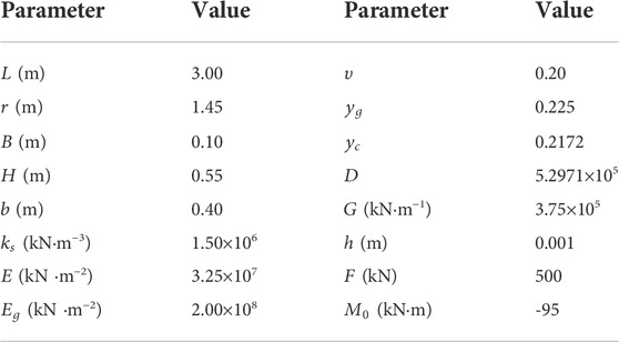
TABLE 1. Parameters of the beam.
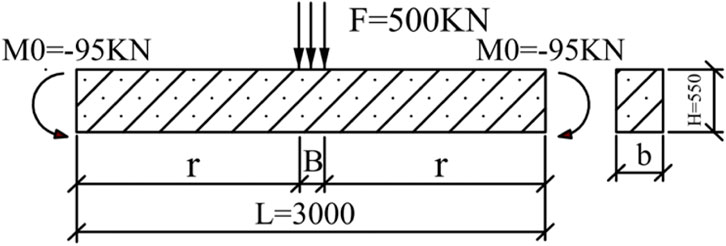
FIGURE 3. Force diagram of the I-beam.
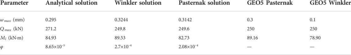
TABLE 2. Calculated results using different models.
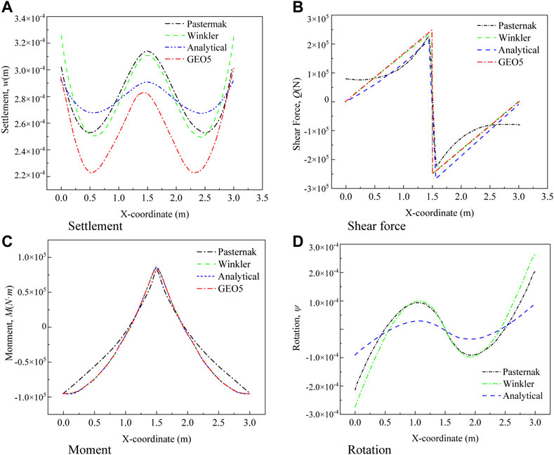
FIGURE 4. Results of the three new methods and GEO5.
It is shown that the calculated internal forces and deformations of the prestressed beam under concentrated force using the three models are quite close.
(1) The sedimentation value calculated by FDM of the Winkler model differs the most, compared with that obtained by GEO5, and the percentage difference is 8.133%. This is partly because the shear deformation was ignored in FDM of the Euler–Bernoulli beam on the Winkler foundation, and the influence of shear deformation on settlement should not be ignored. Minimum variation can be achieved by comparing the sedimentation value calculated by the theoretical analytical solution of the Timoshenko beam on the Winkler foundation with that by GEO5, and the percentage difference is 1.67%.
(2) The differences between the shear force value calculated by the theoretical analytical solution of the Timoshenko beam on the Winkler foundation and via GEO5 are the largest, and the percentage difference is 8.48%. The shear value calculated by FDM of the Winkler model is the closest to that obtained by GEO5, and the percentage difference is 0.08%. This is partly because the shear deformation was ignored in the Winkler foundation, and the value of polynomial terms in the theoretical formula affects the calculated value of the shear force.
(3) The gap in the bending moment value calculated by FDM of the Pasternak model is the largest in comparison with that obtained using GEO5, and the percentage difference is 7.21%; the shear value calculated by FDM of the Winkler model is the closest to that obtained by GEO5, and the percentage difference is 0.42%.
In this article, in order to calculate the internal force and deformation of the prestressed I-beam with prestressed anchorage loads, three theoretical or FDM methods were deduced and verified using GEO5. Main conclusions are as follows:
(1) Three methods, namely, the theoretical model of the Timoshenko beam on the Winkler foundation, the finite difference method of the Euler–Bernoulli beam on the Winkler foundation, and the finite difference method of the Euler–Bernoulli beam on the Pasternak foundation, are proposed, which can be employed to analyze the internal force and deformation of the prestressed I-beam with prestressed anchorage loads.
(2) Among the deformation calculation results of GEO5, the results of the theoretical model of the Timoshenko beam on the Winkler foundation are the closest with a difference of 1.67%, while the results of FDM of the Euler–Bernoulli beam on the Winkler foundation have the largest difference of 8.13%.
(3) Among the shear force calculation results of GEO5, the results of FDM of the Euler–Bernoulli beam on the Winkler foundation are the closest with a difference of 0.08%, while the results of the theoretical model of the Timoshenko beam on the Winkler foundation have the largest difference of 8.48%.
(4) Among the bending moment calculation results of GEO5, the results of FDM of the Euler–Bernoulli beam on the Winkler foundation are the closest with a difference of 0.42%, while the results of the finite difference method of the Euler–Bernoulli beam on the Pasternak foundation have the largest difference of 7.21%.
(5) It can be seen that the results obtained by the corresponding solutions of the three models and the GEO5 calculation results fluctuate within 10%. Whether shear deformation is considered or not, it has little influence on the bending moment. It is feasible to use the aforementioned three models to solve the internal force and deformation of the prestressed I-beam under prestressed anchorage loads.
The original contributions presented in the study are included in the article/Supplementary Material; further inquiries can be directed to the corresponding author.
YY: conceptualization. SW: methodology and writing—original draft preparation. DC: investigation. JY: data curation. PW: writing—original draft preparation. CY and SnW: writing—review and editing.
This study was supported by the Major Topics of the Scientific and Technological Research and Development Plan of China National Railway Group Co., Ltd. (K2021G018).
The authors YY, SW, DC and PW were employed by China Academy of Railway Sciences Corporation Limited, Beijing, China. The authors SW and PW were employed by Beijing Tieke Special Engineering Technological Development Corporation Limited, Beijing, China.
The remaining authors declare that the research was conducted in the absence of any commercial or financial relationships that could be construed as a potential conflict of interest.
All claims expressed in this article are solely those of the authors and do not necessarily represent those of their affiliated organizations, or those of the publisher, the editors, and the reviewers. Any product that may be evaluated in this article, or claim that may be made by its manufacturer, is not guaranteed or endorsed by the publisher.
Cao, R. H., Cao, P., Fan, X., Xiong, X., and Lin, H. (2016). An experimental and numerical study on mechanical behavior of ubiquitous-joint brittle rock-like specimens under uniaxial compression. Rock Mech. Rock Eng. 4911, 4319–4338. doi:10.1007/s00603-016-1029-6
Cheng, S. R., and Wang, D. Z. (1997). Grid anchorage technique and its application to landslide control. Yangtze River 28 (6), 26–28+47.
Leng, J. Y., and Liao, X. P. (2007). Numerical analysis and application study of cross superposition planks. J. Railw. Eng. Soc. 4, 29–33.
Li, J. B., Zhu, Y. P., Ye, S. H., and Ma, X. R. (2019). Internal force analysis and field test of lattice beam based on Winkler theory for elastic foundation beam. Math. Problems Eng. 2019, 1–13. doi:10.1155/2019/5130654
Li, N., Wang, B. Q., Yuan, L. Q., Men, Y., Li, J., and Liu, X. (2020). Seismic response of soil slope reinforced by compression anchor and frame beam based on shaking table test. Arab. J. Geosci. 13 (6), 261–313. doi:10.1007/s12517-020-5262-7
Li, Z. G., Zhao, Y. M., and Zhang, Y. F. (2009). Application of finite difference method in calculation of internal forces of anchor frame beams. J. Highw. Transp. Res. Dev. 26 (04), 7–12.
Liu, Q. Q. (2011). Application of concrete framework prestressed anchor structure for high slope project. Lanzhou University of Technol.
Liu, X. L., Zhang, Z. M., and Deng, J. H. (2004). Pole system finite element analysis for frame foundation beam with prestressed anchor-cable used in reinforced slopes. Rock Soil Mech. 25 (7), 1027–1031.
Ma, Y. J., Peng, S. Q., and Zhou, B. (2004). Comparative analysis of the methods of internal force calculation of the prestressed cable lattice beam for landslide control. J. Geomechanics 10 (4), 366–371.
Qin, X. Y., Zhu, D. P., and Shi, Z. R. (2008). Design and experimental investigation on prestressed anchor-cable lattice beam. J. Yangtze River Sci. Res. Inst. 25 (5), 148–152.
Sheng, X. J., and Lu, H. G. (2021). Numerical simulation of geotechnical prestressed anchor support based on FLAC 3D. Comput. Simul. 38 (02), 206–209+295.
Shi, K. Y., Wu, X. P., Liu, Z., and Dai, S. (2019). Coupled calculation model for anchoring force loss in a slope reinforced by a frame beam and anchor cables. Eng. Geol. 260, 105245. doi:10.1016/j.enggeo.2019.105245
Song, C. J., and Zhou, D. P. (2004). A calculation method of internal force for frame foundation beams with prestressed anchor cable. Highway 7, 76–80.
Wang, Q. C. (2012). Pre-cast high strength pre-stressed concrete lattice test and the study on numerical simulation. Explor. Eng. (Rock Soil Drill. Tunneling) 39 (12), 36–39.
Wu, F. Q., Luo, Y. H., and Chang, Z. H. (2011). Slope reinforcement for housing in Three Gorges reservoir area. J. Mt. Sci. 8 (2), 314–320. doi:10.1007/s11629-011-2109-4
Wu, L. Z., and Huang, R. Q. (2008). Calculation of the internal forces and numerical simulation of the anchor frame beam strengthening expansive soil slope. Geotech. Geol. Eng. (Dordr). 26 (5), 493–502. doi:10.1007/s10706-008-9184-5
Wu, Z. H., and Sun, N. B. (1999). Anchorage technology of concrete frame and lattice beam and its application. Chin. J. Geol. hazard control 10 (4), 91–93.
Xia, G. Y., Li, C. X., and Zeng, Q. Y. (2010). Finite element formulation of Timoshenko beam on Winkler elastic foundation. J. Central South Univ. Sci. Technol. 41 (4), 1549–1555.
Xia, X., and Zhou, D. P. (2006). Application of frame foundation beams with prestressed anchor cable to slope reinforcement. Subgr. Eng. 2, 68–70.
Xiao, J., Li, B. Q., and Wang, X. G. (2013). 3-D stress analysis on cross-beam force transmission lattice for outer fixed end of pre-stressed anchorage cable. Water Resour. Hydropower Eng. 44 (6), 77–81+84.
Yan, J. F., Wang, Q. C., and Yang, D. (2012). Design and analysis on precast high-strength prestressed concrete lattice frame anchor structure. Constr. Technol. 41, 108–110.
Yang, D., Wang, Q. C., and Yan, J. F. (2015). Two rapid set anchor piers and their application in Phoenix Rock unstable slopes. J. Lanzhou Univ. 51 (6), 549–584.
Ye, S. H., Fang, G. W., and Zhu, Y. P. (2019). Model establishment and response analysis of slope reinforced by frame with prestressed anchors under seismic considering the prestress. Soil Dyn. Earthq. Eng. 122, 228–234. doi:10.1016/j.soildyn.2019.03.034
Yin, J. H. (2000). Closed-form solution for reinforced Timoshenko beam on elastic foundation. J. Eng. Mech. 126 (8), 868–874. doi:10.1061/(asce)0733-9399(2000)126:8(868)
Yin, J. H. (2000). Comparative modeling study of reinforced beam on elastic foundation. J. Geotech. Geoenviron. Eng. 126 (3), 265–271. doi:10.1061/(asce)1090-0241(2000)126:3(265)
Zhang, J. J., Niu, J. Y., Fu, X., Cao, L. C., and Yan, S. J. (2022). Failure modes of slope stabilized by frame beam with prestressed anchors. Eur. J. Environ. Civ. Eng. 26 (6), 2120–2142. doi:10.1080/19648189.2020.1752806
Zhang, Y., Wang, Q. C., Yang, D., and Shi, S. W. (2015). The research and application of 500 kN Pre-cast high strength concrete anchorage pier products. J. Eng. Geol. 23, 793–797.
Zhao, Y. L., Liu, Q., Zhang, C. S., Liao, J., Lin, H., and Wang, Y. (2021). Coupled seepage-damage effect in fractured rock masses: Model development and a case study. Int. J. Rock Mech. Min. Sci. 144, 104822. doi:10.1016/j.ijrmms.2021.104822
Zhao, Y. L., Zhang, L. Y., Wang, W. J., Wan, W., and Ma, W. (2018). Separation of elastoviscoplastic strains of rock and a nonlinear creep model. Int. J. Geomech. 18 (1), 04017129. doi:10.1061/(asce)gm.1943-5622.0001033
Keywords: internal force and deformation, prestressed I-beam, elastic foundation, calculation method, Winkler foundation, Pasternak foundation, Timoshenko beam
Citation: Ye Y, Wei S, Cai D, Yang J, Wei P, Yue C and Wu S (2023) Calculation method for internal force and deformation of the prestressed I-beam on the elastic foundation. Front. Earth Sci. 10:996876. doi: 10.3389/feart.2022.996876
Received: 18 July 2022; Accepted: 13 September 2022;
Published: 09 January 2023.
Edited by:
Zhen-Dong Cui, China University of Mining and Technology, ChinaReviewed by:
Shuren Wang, Henan Polytechnic University, ChinaCopyright © 2023 Ye, Wei, Cai, Yang, Wei, Yue and Wu. This is an open-access article distributed under the terms of the Creative Commons Attribution License (CC BY). The use, distribution or reproduction in other forums is permitted, provided the original author(s) and the copyright owner(s) are credited and that the original publication in this journal is cited, in accordance with accepted academic practice. No use, distribution or reproduction is permitted which does not comply with these terms.
*Correspondence: Shaowei Wei, NzUyOTI5Mjc1QHFxLmNvbQ==
Disclaimer: All claims expressed in this article are solely those of the authors and do not necessarily represent those of their affiliated organizations, or those of the publisher, the editors and the reviewers. Any product that may be evaluated in this article or claim that may be made by its manufacturer is not guaranteed or endorsed by the publisher.
Research integrity at Frontiers
Learn more about the work of our research integrity team to safeguard the quality of each article we publish.