 Wenbo Zhang1
 Shaowei Pan
 Zeqin Li
94% of researchers rate our articles as excellent or good
Learn more about the work of our research integrity team to safeguard the quality of each article we publish.
Find out more
ORIGINAL RESEARCH article
Front. Earth Sci., 27 September 2022
Sec. Geochemistry
Volume 10 - 2022 | https://doi.org/10.3389/feart.2022.993876
The complex formation pressure system and diverse formation fluid components during deepwater and deep drilling make it easy for gas intrusion accidents to occur. The dissolution and suspension of the intruded gas in the drilling fluid and the difference between the gas–liquid phase distribution characteristics and the gas–water two-phase flow characteristics in the wellbore lead to errors in the calculation of wellbore pressure and overflow assessment after gas intrusion. In this article, a wellbore multiphase flow model, considering gas dissolution and suspension is established, and the influence of gas dissolution and suspension in the drilling fluid on multiphase flow in the wellbore during overflow, well shutdown, and compression is analyzed with the model calculation results. The higher the drilling fluid density and yield stress are, the higher is the gas limit suspension concentration, when free gas is present in the wellbore. After the gas intrusion shutdown, when there are suspended and transported gases in the wellbore, the rate of pressure increase in the wellbore decreases after the shutdown, and the volume fraction of free gas decreases when the shutdown time is longer, and eventually all the gases will be suspended in the drilling fluid. During the pressure process, gas dissolution leads to an increase in the peak pressure in the wellbore and a delay in its occurrence; gas suspension leads to a decrease in the peak pressure in the wellbore and a delay in its occurrence. This article establishes a multiphase flow calculation model for the wellbore, considering both gas dissolution and suspension, which is a guideline for the calculation of wellbore pressure after gas intrusion.
Accurate calculation of gas–liquid two-phase flow pressure in the wellbore is the basis for pressure-controlled drilling, overflow simulation, and pressure well design. The influence of gas suspension on the gas–liquid phase distribution pattern is not considered in the existing wellbore multiphase flow pressure calculation model, and the gas–liquid two-phase flow pattern transformation in the annulus is not accurate when the drilling fluid viscosity is high. In order to calculate the pressure of gas–liquid two-phase flow in the wellbore more accurately, it is necessary to consider the dissolution, suspension, and transport of the intruding gas in the drilling fluid, and to improve the pressure calculation method of gas–liquid two-phase flow in the drilling wellbore by combining the flow pattern transformation criteria of drilling fluid in the annular flow path and the friction calculation method.
After gas intrusion occurs during drilling of the drilling fluid, Thomas et al. (1984), O'Bryan et al. (1988), O'Bryan et al. (1990) showed that the intruded gas dissolves in the drilling fluid. After the amount of intruded gas exceeds the maximum solubility allowed in the drilling fluid, the gas in the wellbore starts to appear in the drilling fluid as its own gas. Due to the presence of yield stress in the drilling fluid phase, when the amount of free gas is small and the gas meets the suspension conditions, it will all be suspended in the drilling fluid. When the amount of suspended gas exceeds the limit suspension concentration of gas allowed in the drilling fluid, the free gas that cannot be suspended will slip off and rise in the wellbore, and the free gas in the wellbore consists of two parts: suspended gas and transport gas. As the volume fraction of transport gas increases, different flow patterns such as bubbling flow, segment plug flow, churning flow, and annular mist flow start to appear in the drilling annulus, and the gas properties also change.
Because the change mechanism of gas solubility in the drilling fluid after gas invasion is complex and difficult to predict, domestic and foreign scholars have conducted a large number of experimental studies on gas solubility in the drilling fluid and established and improved the prediction model of gas solubility in the drilling fluid based on experimental results and theoretical analysis.
Thomas et al. (1984) measured the solubility of methane in diesel oil in the temperature range of 311–589 K and pressure range of 0–68.9 MPa. Before falling to the bubble point line, the gas was all liquid (dissolved in the drilling fluid). O'Bryan et al. (1988) measured the solubility of C1, C2, and CO2 and natural gas mixture in base oil, emulsifier, and different drilling fluids in the range of 311–423 K and the same pressure. It was found that C1 was mainly dissolved in base oil, and a solubility calculation model obtained by weighted average of solubility volume integral of each component in drilling fluid was proposed.
where RSm is the solubility of gas in drilling fluid; RSo is the solubility of gas in base oil; Eo is the volume fraction of base oil; RSw is the solubility of gas in brine; Ew is the volume fraction of brine; RSe is the gas solubility in emulsifier; Ee is the volume fraction of emulsifier; RSo,i is the solubility of component i in the base oil, and i is C1, C2, CO2, etc; fi is the volume fraction of component i.
O'Bryan et al., 1988 proposed empirical equations for calculating the solubility of C1, C2, CO2, and other gases in the wellbore based on experimental data.
where ai, bi, ci, and di are empirical coefficients measured according to the dissolution experiment of each component.
In China, Xue et al. (2005) measured the solubility of methane, carbon dioxide, and nitrogen in crude oil in the temperature range of 308–348 K and pressure range of 1.2–20 MPa. Through mechanism analysis and experiments, a semiempirical model for calculating the solubility of gas in drilling fluid was established. Fu et al. (2012) combined the model of O'Bryan et al. (1988) with the gas solubility model in water to calculate the gas solubility distribution in the drilling fluid in the wellbore. Wang et al. (2008), Wang et al. (2017) found a new hydrocarbon gas solubility model in the oil phase using previous experimental data and verified the model with new experimental results.
where RSo, h is the solubility of hydrocarbon gas in the drilling fluid. The coefficients ah,bh, and nh are 11.773, 0.122, and 1.29, respectively.
Using the empirical model within the experimental temperature and pressure range can quickly obtain the results within the allowable error range, but the accuracy of the prediction results outside the experimental temperature and pressure range remains to be verified.
In addition to empirical models, the calculation method of solubility based on gas–liquid phase equilibrium is also commonly used, and the fugacity equilibrium method based on equation of state is the most widely used method. Feng et al. (2019) conducted experimental research on the solubility of gas in various drilling fluids and found that the calculation method using PR equation of state combined with two parameter mixing rules has the best accuracy, and its model has been widely adopted by Manikonda et al. (2019), Sleiti et al. (2020), and other scholars.
Sun et al. (2017) found that the dissolution process of gas in the drilling fluid is essentially the diffusion of gas molecules in the gas phase into the liquid phase under the action of fugacity difference, and the dissolution rate is related to the diffusion coefficient and gas–liquid interface area. The precipitation of dissolved gas is usually considered as a flash process, and its speed can be ignored in the calculation. Fu et al. (2019), Fu et al. (2022a), Fu et al. (2022b), Fu et al. (2022c) studied the dissolution characteristics of gases in a series of hydrate containing water-based drilling fluids, which verified the above conclusions.
Due to the existence of maximum solubility of the drilling fluid, after gas intrusion occurs during the drilling process, when the amount of intruded gas exceeds the maximum solubility allowed in the drilling fluid, the gas in the wellbore will appear in the drilling fluid as its own gas. Due to the presence of yield stress in the drilling fluid phase, when the amount of free gas is small and the gas meets the suspension conditions, it will all be suspended in the drilling fluid. The particles of other phases dispersed in the yield stress fluid will tend to move in the direction of gravity because of the presence of density difference, and the presence of yield stress will impede the flow of liquid mass around the particles. When the gravity difference between the particles and the drilling fluid is not sufficient to overcome the resistance generated by the yield stress, the dispersed phase will be bound in the drilling fluid without slippage. In this article, this non-slip state of the dispersed phase is called “suspended state.”
Beris et al. (1985) found that when studying the suspension phenomenon of solid spheres in yield stress fluid, it was found that the maximum diameter of a single sphere that can remain suspended was related to density difference and liquid phase yield stress, and proposed to use the critical value Bnc of dimensionless number Bn (dimensionless number representing the ratio of yield stress to gravity) to characterize the critical suspension condition of spheres. When Bn≥Bnc, the pellets can be suspended in the liquid phase.
where Bn is the Bingham number, dimensionless; τy is the liquid yield stress, Pa; ρL is the yield stress fluid density, kg·m−3; ρi is the density of dispersed phase, kg·m−3; g is the acceleration of gravity, m·s−2; Ri is the dispersion equivalent radius, m; s,L, and g represent solid, liquid, and gas, respectively.
Different from solid pellets, bubbles suspended in drilling fluid will deform with the increase of volume. Dubash and Frigaard (2004), Dubash and Frigaard (2007) calculated the critical suspension conditions of axisymmetric bubbles by assuming the size of the disturbed region around the bubbles and using the variational principle. However, compared with the experimental results, the suspension condition Bnc obtained by the model is much larger than the experimental value. Tsamopoulos et al. (2008) and Dimakopoulos et al. 2013 simulated the suspension conditions of a single bubble by using numerical simulation and found that the greater is the bubble deformation, the greater is the Bnc value of the critical suspension condition. It is also found that there is a finite yield region caused by buoyancy near the equatorial plane of the suspended bubble and close to the gas–liquid interface.
Sikorski et al. (2009) found that in addition to the yield stress, the liquid elastic modulus also affects the critical suspension condition of a single bubble. The gas critical suspension condition obtained from the experiment (Bnc=0.72, 1.08) is much larger than the numerical simulation result (Bnc range 0.221–0.318). Sikorski et al. (2009) also proposed to use the dimensionless number Y representing the ratio of resistance to buoyancy at the maximum width of the bubble as the critical criterion for bubble suspension, according to the experimental results. The critical suspension conditions Yc are 0.46 and 0.53, respectively, in the solution with a yield stress of 24.1 and 33.5 Pa. Samson et al. (2017) also used this method to characterize the critical suspension condition of bubbles. Yc was 0.52 in the yield stress of 40 Pa. The experimental results show that the resistance on the gas–liquid interface of bubbles is significantly less than the buoyancy, that is, Yc<1. Sikorski et al. (2009) believed that in addition to the yield stress, the liquid phase modulus of elasticity would also affect the critical suspension condition of a single bubble.
where Y is a dimensionless number; Rmax is the radius at the maximum width of the bubble, m; and Vb is the volume of suspended bubbles, m3.
After gas intrusion occurs in the drilling wellbore, the gas is usually dispersed in the drilling fluid in the form of bubble clusters. When multiple bubbles in a bubble cluster meet the single bubble suspension condition at the same time and the distance between bubbles is far enough, there will be multiple bubbles suspended in the drilling fluid at the same time. The total volume of suspended bubbles in the drilling fluid per unit volume is the gas suspension concentration. The characteristics of gas–liquid two-phase distribution in the wellbore after gas suspension are different from the traditional gas–water two-phase flow law, which leads to inaccurate calculation results of the traditional multiphase flow model in the wellbore after gas intrusion, and the greater is the well depth, the greater is the influence.
There are few studies on gas suspension concentration in the drilling fluid. Liu et al. (2021) carried out the experiment of gas limit suspension concentration and found that the gas suspension phenomenon caused by the yield stress of the drilling fluid affected the accurate calculation of wellbore pressure after gas invasion. For different gas invasion modes, a method using dimensionless numbers to characterize the gas suspension concentration was proposed. After that, Pan et al. (2022) established a theoretical model for calculating the maximum gas entrapment concentration (mgec) for the first time and proposed a calculation method of gas limit suspension concentration. The predicted results of the model are in good agreement with the experimental results, which is of great significance for the study of gas suspension concentration in the drilling fluid.
In this article, a multiphase flow calculation model of wellbore considering gas dissolution in drilling fluid after gas intrusion and gas suspension in the wellbore under different flow patterns is developed. The model results are used to analyze the influence of multiphase flow in the wellbore during the overflow, shut-in, and compression processes.
Accurate calculation of gas–liquid two-phase flow pressure in the wellbore is the basis for pressure-controlled drilling, overflow simulation, and pressure well design. The existing model for calculating multiphase flow pressure in the wellbore does not take into account the influence of gas suspension on the gas–liquid phase distribution pattern, and the inaccurate flow pattern transformation criterion of gas–liquid two-phase flow in the annulus when the drilling fluid viscosity is high, and the error of friction coefficient in the wellbore will lead to inaccurate calculation of multiphase flow pressure in the wellbore. This chapter establishes a pressure calculation method applicable to the gas–liquid two-phase flow in a drilling wellbore, taking into account the dissolution, suspension, and transport of the intruding gas in the drilling fluid, combined with the gas–liquid two-phase flow transformation criterion and friction calculation method in the annular flow path.
The dissolution and suspension of gas in the drilling fluid after intrusion into the wellbore and the low-temperature and high-pressure conditions at the bottom of the sea during deepwater drilling can also lead to the combination of the intruded gas with water in the drilling fluid to produce hydrates. In this article, the following assumptions are made in establishing the wellbore homogeneous multiphase flow equation:
1) Only gas suspension exists in the continuous liquid phase, ignoring the effect of droplets on the liquid phase content in Taylor under segment plug flow conditions, that is, gas suspension exists in all liquid phases under vesicular flow, segment plug flow, and churning flow conditions, and only gas suspension exists in the liquid film under annular mist flow conditions.
2) Ignore the effects of hydrate phase change and gas dissolution on drilling fluid rheology.
3) Assume that the temperature field in the wellbore is uniformly distributed in the same well depth section, and the pressure in the drill pipe and in the annulus is uniformly distributed in the same well depth section.
4) Assume that thermodynamic properties such as specific heat capacity and thermal conductivity of the wellbore casing, cement ring, and formation do not change with time during drilling and after the onset of gas intrusion.
5) When there is hydrate generation, it is assumed that the hydrate phase velocity and drilling fluid phase velocity are equal; hydrate generation does not affect drilling fluid density, and hydrate deposition plugging does not occur.
The free gas in the wellbore after gas intrusion occurs is divided into two parts: transport gas and suspended gas. The gas suspended in the drilling fluid is the small bubbles generated by the gas–liquid interface broken by the turbulent impact, and the transport gas continues to generate small bubbles as it slips and rises in the drilling fluid. Therefore, the free gas in the wellbore is preferentially in the form of suspended gas, and the part exceeding the suspended concentration is in the form of transport gas. The suspended gas has the same velocity as the drilling fluid and the same physical properties as the transported gas, so the velocity-related items in the gas-phase continuity equation need to be split into two subterms, suspension and transport, to establish the gas-phase continuity equation when considering gas suspension as follows.
where A is the annulus sectional area, m2; αg, s is the volume fraction of suspended gas; αg, m is the gas holdup of migration gas; vg is the gas drift velocity, m·s−1; vL is the flow rate of the drilling fluid, m·s−1; mg, H is the gas consumption of hydrate formation in the cell, kg·m−1; mg, R is the dissolved amount of gas, kg·m−1; and qg is the inflow rate of external gas, kg·m−1·s−1.
The continuity equation of the drilling fluid is:
where αL is the volume fraction of the liquid phase, m·s−1; and mL, H is the water consumption for hydrate formation in the cell, kg·m−1.
The hydrate phase continuity equation is:
where ρH is the hydrate density, kg·m−3; and mH is the amount of hydrate generated in the cell, kg·m−1.
Hydrate is generated by invading gas and drilling fluid under appropriate temperature and pressure conditions, and the water consumption and gas volume are equal to the amount of hydrate generated.
The sum of all phases in the wellbore is one:
When all the gas is suspended, αg, m in Eq. 7 is 0. When all the gas is dissolved in the drilling fluid, αg, s and αg, m in Eq. 7 are 0. When hydrate formation is not considered, mg, H,mw, H, and mH in Eq. 10 are all 0.
The pressure drop in the wellbore in the drift flow model is composed of three parts: mixed phase momentum, mixed phase hydrostatic column pressure, and mixed phase friction pressure. During the multiphase flow in the wellbore, the momentum of the gas phase and drilling fluid phase decreases due to hydrate generation and increases due to the hydrate phase, and the momentum of gas phase dissolution into the drilling fluid decreases and increases due to the drilling fluid phase; therefore, the momentum change due to gas dissolution and hydrate phase change is zero. The mixed phase momentum in the wellbore is conserved by the following equation:
where j represents the drilling fluid, migration gas, suspended gas, and hydrate; ph is the hydrostatic column pressure, and Pa; pf is the friction pressure, Pa.
The gas velocity suspended in the drilling fluid is the same as that of the drilling fluid. It is assumed that the hydrate phase velocity after formation is equal to that of the drilling fluid. The first two items in Equation 12 represent the velocity head in the shaft, which is expanded as:
The expansion formulas of hydrostatic column pressure term and friction pressure drop term in the wellbore are respectively:
Record the mixing density of gas–liquid phase as ρM. The expanded momentum conservation equation of the mixed phase can be obtained by introducing equation 13–16 into Equation 12.
Since Hasan et al., 1998 proposed the heat transfer model in the wellbore, scholars at home and abroad have conducted a lot of research on the heat transfer model and its application in the wellbore, and the traditional heat transfer model in the wellbore has been more mature. In this section, we mainly consider the influence of gas suspension on the calculation of the fluid temperature field in the wellbore and modify the energy conservation equation in the wellbore.
The energy conservation equation is established, assuming a uniform distribution of mixed phase fluid temperature in the wellbore in the radial direction, with the formation intrusion fluid temperature being the same as the formation temperature at the bottom of the well, neglecting frictional heat loss, exothermic gas dissolution, and exothermic hydrate phase change. The heat transfer process in the wellbore cell is shown in Figure 1, where the formation (or seawater) heat is transferred into the wellbore fluid through the cement ring layer and the casing layer (or the spacer layer).
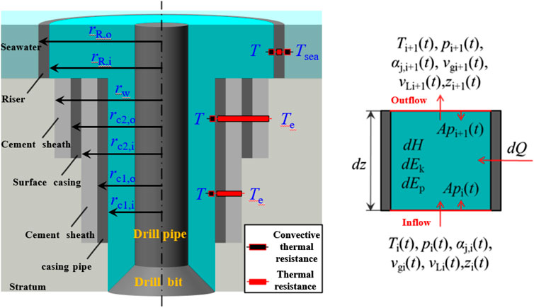
FIGURE 1. Schematic of heat transfer in drilling wellbore.
The energy change of the mixed phase fluid in the cell includes internal energy change, Joule–Thompson effect during gas expansion, kinetic energy change, potential energy change, external work, and heat transfer between the wellbore and the formation. The sum of internal energy change and Joule–Thompson effect during gas expansion is the enthalpy change of the mixed phase, and the work done by external force in one-dimensional flow without considering frictional heat is the work done by pressure at the upper and lower ends of the cell, and the energy conservation equation is:
where H is the mixing relative enthalpy, W·m−1; Ek is the kinetic energy of the mixed phase, W·m−1; Ep is the gravitational potential energy of the mixed phase, W·m−1; Q is the heat transfer between formation and wellbore, W·m−1.
The enthalpy change of mixed phase in the wellbore includes the change of internal energy and the Joule–Thompson effect of gas. Ignoring the influence of gas dissolution and hydrate phase transition on the specific heat capacity of drilling fluid, the enthalpy change can be obtained as:
where Cp, g is the specific heat capacity of gas, J·kg−1·K−1; Cp, L is the relative heat capacity of the drilling fluid, J·kg−1·K−1; Cp, H is the relative heat capacity of hydrate, J·kg−1·K−1; CJ is the Joule–Thompson coefficient of gas, K·Pa−1.
The kinetic energy conservation equation of the mixed phase in the wellbore changes as follows:
The variation of gravitational potential energy of the mixed phase in the wellbore is:
The work done by the pressure in the wellbore is:
The heat transferred from the formation into the wellbore includes the heat transferred by the formation through the cement sheath, casing (or riser), and the heat carried by the formation fluid into the wellbore. It is assumed that the temperature of the mixed phase fluid in the wellbore is the same as that in the drill pipe.
where Uf is the comprehensive heat transfer coefficient between annulus fluid and formation section (or seawater section), Wm·K−1; Te is the temperature of formation section (or seawater section), K;
The offshore drilling wellbore is divided into two parts: the seawater section and the formation section. The seawater section is separated from the wellbore by a riser. The thermal resistance between the seawater section and the wellbore fluid includes three parts: the convective thermal resistance between the seawater section and the riser, the thermal conductivity of the riser, and the convective thermal resistance between the wellbore fluid and the riser. When the well depth is less than the water depth, the comprehensive heat transfer coefficient in the annulus fluid and seawater section is:
where Ra, R is the convective thermal resistance between wellbore fluid and riser, K·W−1·m−1; RR is the thermal conductivity resistance in the riser, K·W−1; Rsea is the convective thermal resistance between seawater and riser, K·W−1·m−1; Hw is the water depth of offshore drilling; m; rR, i is the inner diameter of riser, m; ha is the convection heat transfer coefficient between the annulus fluid and the inner wall of the casing (or riser), W·K−1; λc is the thermal conductivity of riser (or casing), Wm·K−1; rR, o is the outer diameter of riser, m; and hsea is the convective heat transfer coefficient between seawater and the outer wall of riser, W·K−1.
When the well depth of land drilling or offshore drilling is greater than the water depth, the heat transfer between the formation and the wellbore above the innermost casing shoe depth includes the heat transferred into the wellbore through each layer of cement sheath and casing and the heat carried by the formation fluid invading the wellbore.
where Ra, c is the convective thermal resistance between wellbore fluid and casing, K·W−1·m−1; Rc is the thermal conductivity resistance in each layer of casing, K·W−1; Rce is the thermal conductivity resistance in each cement sheath, K·W−1; Hc1f is the well depth at the first casing shoe, m; rci, i is the inner diameter of the ith casing, m; rco, i is the outer diameter of the ith casing, m; λce is the thermal conductivity of cement sheath, Wm·K−1; and rceo, N is the outer diameter of the outermost cement sheath, m.
The well section below the innermost casing shoe depth is in direct contact with the formation. The heat transfer resistance between the formation and the wellbore is the convection heat resistance between the wellbore fluid and the body layer, and the comprehensive heat transfer coefficient is:
where Rw is the borehole diameter, m; and he is the convection heat transfer coefficient between wellbore fluid and formation, W·K−1.
Bring Equations 20–24 into Equation 19 to obtain the energy conservation equation in the wellbore.
Because the number of control equations is less than the number of unknowns, in order to ensure that the equations can be closed, it is also necessary to establish the control equations of multiphase flow in the wellbore. This chapter mainly introduces the calculation model of gas solubility and the empirical formula for rapid calculation of gas limit suspended concentration. Auxiliary equations such as flow pattern transformation criterion, friction pressure drop calculation, gas invasion velocity, and gas migration velocity are widely used in the literature.
The experimental and theoretical studies on gas solubility in drilling fluids have been relatively mature, and the multiphase flow calculation process in this article uses the method based on the fugacity equilibrium, PR equation of state, and two parameter mixing rule to calculate the gas solubility in the drilling fluid base oil, the method proposed by Sun et al. (2017) is used to calculate the gas dissolution rate, and the model established by Manikonda et al. (2020) is used to calculate the drilling fluid swelling volume. See Supplementary Appendix SA for details.
A 1000-m vertical well section is taken as an example, and the basic data of the well is shown in Table 1.
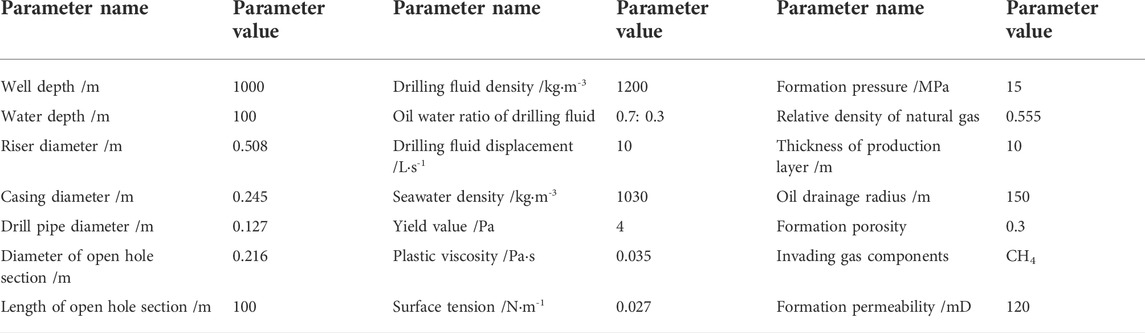
TABLE 1. Basic data of case well.
Under the same gas influx, the gas distribution characteristics in the wellbore with and without gas dissolution are shown in Figure 2. The red curve in Figure 2A shows the gas distribution characteristics in the wellbore when the mud pit reaches 1.5 m3 regardless of gas dissolution. The volume fraction of migrating gas at the bottom of the well is about 0.201. In the simulation calculation, the time for the mud pit increment to reach 1.5 m3 is about 221 s. Due to the existence of gas slippage, the well depth at the front edge of the gas body in the wellbore is about 740 m. When considering gas dissolution under the same gas influx, the invaded gas is completely dissolved in the drilling fluid, and the volume fraction of migration gas is zero, as shown by the solid blue line in Figure 2A. When the drilling fluid containing dissolved gas increases in the wellbore, the maximum solubility of gas in the wellbore gradually decreases. The contaminated drilling fluid increases to 430 m deep and begins to desolvate. Free gas begins to appear in the wellbore. The trailing edge of the contaminated drilling fluid increases to 430 m deep. The volume fraction of transported gas in the wellbore is shown by the blue-dotted line in Figure 2A. The void ratio of transported gas at 340 m deep is about 0.123.
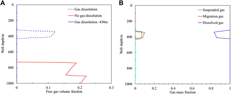
FIGURE 2. Gas distribution in wellbore annulus after gas invasion under drilling condition. (A) Volume fraction of migration gas with or without dissolution. (B) Mass fraction of migration gas and dissolved gas during gas dissolution.
When there is gas dissolution, the invaded gas exists in the form of migration gas and dissolved gas. After the trailing edge of the gas increases to 430 m well depth, the mass fraction of migration gas and dissolved gas in the invaded gas is distributed in the wellbore as shown in Figure 2B. As the well depth decreases, the mass fraction of dissolved gas also gradually decreases, and the mass fraction of transported gas gradually increases. The mass fraction of dissolved gas in the well section with a well depth of 430–330 m decreases from 94.78 to 92.64%.
In order to ensure good gel strength, the drilling fluid usually has a large modulus of elasticity, the G'/τy value is generally above 15. Qiu et al. (2015) measured the elastic modulus of the drilling fluid in the experiment, but it was not given in the experiment that the elastic modulus has been in an increasing state and did not reach the peak value during loud yield flow. According to the experimental results, it can be seen that the elastic modulus of drilling fluid after aging ranges above 85 Pa, and the actual yield stress is 6.05 Pa. In the experiment of Ettehadi et al. (2022), the elastic modulus range of the two groups of the aged drilling fluid is 271 and 388 Pa, respectively, but the yield stress is not given in the experiment. Werner et al. (2017), the elastic modulus was 27.8 and 37.6 Pa, and the yield stress of aging drilling fluid was 1.7 and 2 Pa, respectively.
Under the action of yield stress, there is suspension of gas, and there is dissolution of gas in the drilling fluid, which leads to three forms of gas invasion in the wellbore: dissolution, suspension, and migration, of which suspended gas and migration gas are free gases.
When the formation gas enters the wellbore by diffusion gas intrusion, all the intruded gas at the bottom of the wellbore will be dissolved in the drilling fluid due to the small rate of gas entering the wellbore, as shown in Figure 3A. As the contaminated drilling fluid increases and the wellbore pressure decreases, the intruded gas will dissolve and form small bubbles dispersed in the drilling fluid, and the intruded gas will be distributed in the wellbore in both dissolved and suspended forms, with all free gas in the wellbore in suspension and no transport gas present. When the free gas volume fraction exceeds the gas limit suspension concentration, the free gas in the wellbore begins to transport, and the gas in the wellbore exists in three forms: transport, suspension, and dissolution.
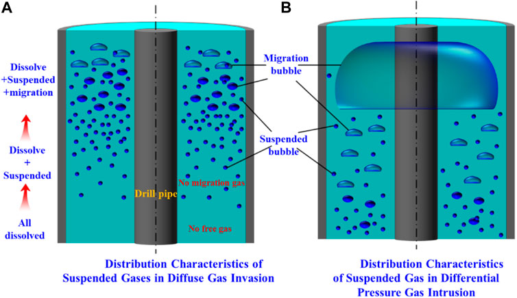
FIGURE 3. Distribution of entrapped bubbles. (A) Distribution of suspended gas in wellbore under different drilling fluid density. (B) Distribution of suspended gas in wellbore under different drilling fluid yield stress.
After pressure differential gas intrusion occurs, the gas in the wellbore exists in three forms: transport, suspension, and dissolution due to the limited gas suspension concentration in the drilling fluid at the bottom of the well. At the same time, as the volume fraction of transported gas changes, the wellbore exhibits different flow patterns, such as bubbling flow, segmental plug flow, stirring flow, and annular mist flow. The suspended gas is distributed around the transport bubble under the bubble flow condition, and the fluid area except Taylor bubble is similar to the bubble flow under the segment plug flow condition, as shown in Figure 3B.
During the free gas intrusion process, the gas–liquid interface in the wellbore will break up and merge under the effect of turbulent kinetic energy. The critical radius can be calculated by the model proposed by Brodkey et al. (1980).
Jiang et al. (2021) found that the interfacial tension of the drilling fluid base oil (white oil and gas to oil) was about 26.29 mN m−1 at 298.15 K. With the increase of temperature, the interfacial tension would gradually decrease. When the temperature increased from 290.15 to 353.15K, the interfacial tension decreased from 26.3 to 22.81 mN m−1. According to the experimental results, the interfacial tension at different temperatures is:
where T298.15 is the reference temperature, taking 298.15K; σ298.15 is the interfacial tension at the reference temperature, taking 26.29 mN m−1.
After determining the equivalent radius of suspended bubbles, the Bn value of suspended bubbles in the wellbore can be obtained according to parameters such as drilling fluid density and yield stress. When there is no migrating gas in the wellbore (diffusive gas influx), the limit suspended concentration of gas can be calculated by the model established by Pan et al. (2022). When there is migrating gas, the limit suspended concentration of gas under different working conditions is related to the flow pattern in the wellbore. The distribution characteristics of suspended gas under bubbly flow are the same as those in this experiment, which can be calculated by the model established by Pan et al. (2022). Volume fraction of suspended gas αg, s is:
where VFc uses the suspension calculation model in Pan et al. (2022):
When the gas–liquid two-phase flow in the wellbore is slug flow or turbulent flow, there are large fan-shaped Taylor bubbles or deformed atmospheric masses in the wellbore, and the gas cannot be suspended in them. Assuming that the gas–liquid two-phases except the fan ring Taylor bubble and the atmospheric mass are in a bubbly flow state that is about to change into slug flow or turbulent flow, the void ratio of the fan ring Taylor bubble or the deformed atmospheric mass is αg. T, when the bubbly flow is transformed into the next flow pattern, the corresponding void ratio is αg,b, then the total void ratio and total liquid holdup in wellbore cells are:
When the bubbly flow is transformed into the next flow pattern, the corresponding void ratio is αg,b can be calculated from the criterion, apparent gas velocity, apparent liquid velocity, and gas slippage velocity during the conversion of bubbly flow to slug flow or agitated flow.
According to Eq. 39, the volume fraction of suspended gas under slug flow or agitated flow is:
When the flow pattern in the wellbore is annular fog flow, the liquid holdup is very low, and the influence of suspended gas on the wellbore pressure calculation can be ignored.
When diffusion gas intrusion occurs during drilling of the drilling fluid, all the gas entering the wellbore is in dissolved state because the rate of diffusion gas intrusion into the wellbore is very low. Dissolved gas is not present in the wellbore until the drilling fluid reaches the depth of the well at the point of precipitation, then as the drilling fluid containing dissolved gas increases, the precipitated gas is evenly distributed in the drilling fluid, and the gas suspension concentration gradually increases from zero to the limit suspension concentration allowed by diffusion gas intrusion. When the precipitated gas continues to increase, transport gas starts to appear in the wellbore, and the gas suspension concentration in the wellbore drops to the same suspension concentration as the pressure differential gas intrusion under vesicular flow conditions, and a large amount of free gas starts to slip off and rise, that is, the gas suspension phenomenon consistent with diffusive gas intrusion only occurs in a well section within a certain well depth range.
After diffusive gas influx occurs in a well section, the limit suspended concentration of gas in diffusive gas influx is sensitive to the change of liquid yield stress and density. When the interfacial tension of the drilling fluid is 27 mN m−1 and the density of the drilling fluid is reduced from 2000–1000 kg m−3, the average radius of suspended bubbles in the wellbore increases from 0.371 to 0.525 mm according to Equation 36, and the minimum yield stress values in the presence of gas suspension are 1.10 and 0.78 Pa, respectively, according to Bnc=0.226. The minimum yield stress values when the gas in the diffusion gas invasion reaches the maximum suspension concentration of 0.2143 are 1.33 and 0.94 Pa, respectively, and the yield stress values of most drilling fluids are 1.7 Pa or above, that is, the limit suspension concentration of the diffusion gas invasion gas under most working conditions is 0.2143.
Using the parameters of the example well in Table 2, the gas distribution characteristics under the condition of diffusion gas influx are simulated. The gas influx is equal to the gas influx with the mud pit increment of 1.5 m3 when gas dissolution and suspension are not considered. All the invaded gas at the bottom of the well is suspended in the drilling fluid. As the polluted drilling fluid increases, the solubility of the gas in the drilling fluid gradually decreases. The mass number of dissolved gas in the drilling fluid at different well depths is shown in the black curve in Figure 4A.
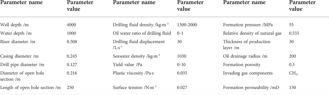
TABLE 2. Basic data of simulation well.
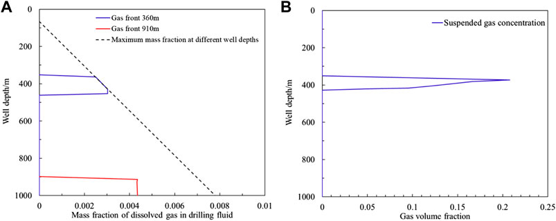
FIGURE 4. Gas distribution in wellbore annulus after diffusion gas invasion under drilling condition. (A) Mass fraction of dissolved gas in drilling fluid after diffusive gas invasion. (B) Volume fraction of suspended gas after diffusion gas invasion.
When the contaminated drilling fluid increases to 430 m deep, gas desolvation and precipitation begin to occur, and all the precipitated gas is suspended in the drilling fluid. The volume fraction of free gas released by desolvation after the drilling fluid increases to the well depth of 360 m exceeds the allowable gas limit suspension concentration of diffusion gas invasion by 0.2143, as shown in Figure 4B, that is, migration gas will appear when the contaminated drilling fluid continues to increase.
The length of the contaminated drilling fluid section is about 90 m under the simulated conditions of the example well. With the increase of the contaminated drilling fluid, only a small part of the well section meets the gas distribution form (dissolution + suspension) in the wellbore after the diffusion gas invasion. In the case well, the length of the gas suspension well section that meets the form of diffusion gas invasion is 360–430 m, and the gas distribution in the well section with smaller well depth will change into a distribution form similar to the differential pressure gas invasion (dissolution + suspension + migration).
After differential pressure gas invasion, the insoluble free gas in the wellbore will be suspended. When the total void ratio of free gas (the sum of suspended gas and migration gas) exceeds the maximum allowable volume fraction of suspended gas under differential pressure gas invasion, migration gas will appear in the wellbore. Using the parameters of the example well in Table 2, the gas distribution characteristics under the differential pressure gas influx condition are simulated. The gas influx is equal to the gas influx with the mud pit increment of 1.5 m3 when gas dissolution and suspension are not considered. The change law of the mass fraction of dissolved gas in the drilling fluid is the same as that in Figure 4. The contaminated drilling fluid begins to precipitate when it reaches the well depth of 430 m.
When the yield stress of drilling fluid is 4 Pa and the surface tension is 27 mN m−1, the calculated ultimate suspended concentration of gas at the bottom of the well is about 0.05. The free gas in the wellbore after desolvation and precipitation of dissolved gas is divided into suspension and migration. The slippage and rise of migration gas will lead to the increase of the length of the contaminated drilling fluid section in the wellbore. When the gas front increases to a well depth of 320 m, the volume fraction of free gas in the well section with a well depth of 430–320 m is shown in Figure 5A, the volume fraction of suspended gas is about 0.05, and the volume fraction of transported gas increases from 0 to 0.0718. The mass fraction distribution of migration gas, suspended gas, and dissolved gas in the invaded gas is shown in Figure 5B. As the well depth decreases, the mass fraction of dissolved gas decreases from 0.948 to 0.927.
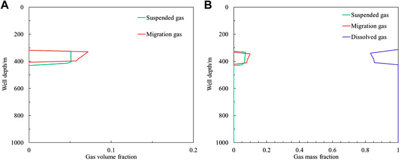
FIGURE 5. Gas distribution in wellbore annulus after pressure difference gas invasion under drilling condition. (A) Gas volume fraction in wellbore after differential pressure gas influx. (B) Gas mass fraction in wellbore after differential pressure gas influx.
Other auxiliary equations include formation of fluid invasion velocity model, wellbore fluid loss velocity calculation model, and wellbore gas migration velocity calculation model, see Supplementary Appendix SA for details.
The core solution flow of the multiphase flow model in this article is shown in Figure 6.
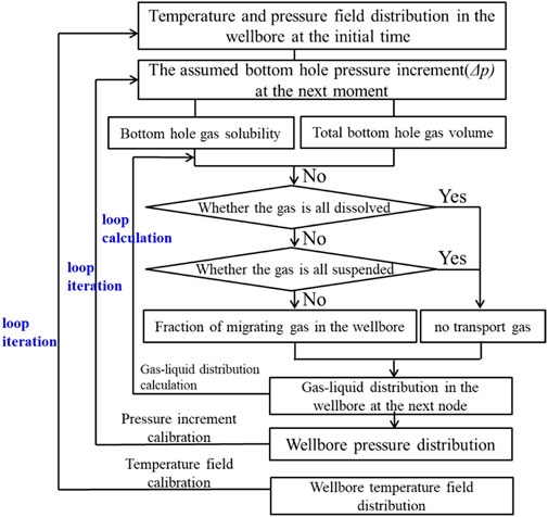
FIGURE 6. Flow chart for solving the gas–liquid two-phase flow model.
After an overflow occurs in a drilled wellbore, the multiphase flow pattern in the wellbore is affected by the fluid properties such as drilling fluid physical properties and rheology. Based on the wellbore multiphase flow model established in this article, a calculation software applicable to wellbore multiphase flow law and wellbore pressure simulation is prepared by using VB.net, which can be used for overflow simulation, multiphase flow law in the wellbore after well shutdown based on overflow simulation results and multiphase flow law in the wellbore during conventional well compression. It provides theoretical support for wellbore pressure control by simulating multiphase flow and pressure changes in the wellbore under different drilling fluid properties, drilling environments, and operating conditions.
Refer to the parameters of example wells in Table 2 for the parameters of simulation wells.
After overflow occurs during drilling, when gas dissolution and suspension are not considered, the variation law of mud pit increment in the wellbore with time is shown in Figure 7. With the increase of overflow time, the continuous invasion and migration of gas and the expansion of gas lead to the increase of mud pit increment. The mud pit increment is 1 m3 after 4.42 min of overflow, 2 m3 after 8.23 min of overflow, 3 m3 after 11.53 min, 4 m3 after 14.49 min, and 5 m3 after 17.18 min.
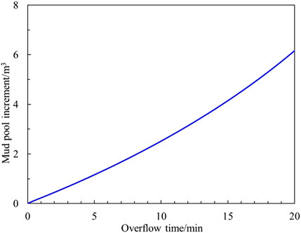
FIGURE 7. Mud pool increment after overflow occurred during drilling.
The distribution law in the wellbore under different gas influx is shown in Figure 8. With the migration and expansion of the invaded gas, the gas volume fraction in the wellbore gradually increases. With the increase of gas influx, the liquid column pressure in the wellbore decreases, the difference between formation pressure and bottom-hole pressure increases, and the gas porosity at the bottom of the well increases. When the gas influx is 1 m3, the gas volume fraction at the bottom of the well is 0.0876, and when the gas influx is 2, 3, 4, and 5 m3, the porosity at the bottom of the well is 0.0933, 0.1011, 0.1087, and 0.1155, respectively.
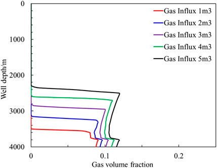
FIGURE 8. Gas distribution pattern in the wellbore under different gas intrusion volume.
With the increase of gas influx, the wellbore pressure gradually decreases, and the larger is the gas porosity at the same well depth, the faster is the rising speed. When the gas influx is 1 m3, the gas front position is 3550 m, and when the gas influx is 2, 3, 4, and 5 m3, the gas front position is 3200, 2850, 2550, and 2300 m, respectively.
In the process of drilling, the mud pit increment of 2 m3 is generally used as the shut under condition after overflow. When gas dissolution and suspension are not considered, the overflow time is 8.23 min when the volume of invaded gas is 2 m3, and the total mass of invaded gas is about 476 kg. The oil–water ratio of drilling fluid in the example well is 0.8:0.2, and the gas distribution characteristics in the wellbore after the same mass gas invades the wellbore are shown in Figure 9.
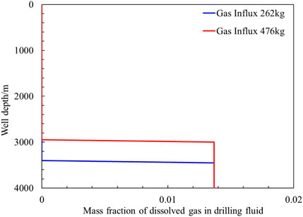
FIGURE 9. Distribution pattern of dissolved gas in the wellbore under different gas intrusion volume.
All the invaded gas at the bottom of the well is dissolved in the drilling fluid. Since the dissolved gas in the drilling fluid does not reach the saturation solubility, the mass fraction in the drilling fluid is always 0.0137. Regardless of gas dissolution and suspension, the bottom-hole pressure gradually decreases with the increase of gas influx, and the gas influx rate gradually increases. All the invaded gas is dissolved in the drilling fluid, the bottom-hole pressure is almost unchanged during the gas invasion process, and the gas invasion rate is less than the result when gas dissolution and suspension are not considered. In addition, when the dissolved gas does not slip, the rising speed of the gas front is also less than that when the gas dissolution and suspension are not considered. When the overflow time is 8.23 min, the gas distribution characteristics in the wellbore are shown in the blue curve in Figure 9. The total mass of the invaded gas is about 262 kg, and the well depth at the front edge of the gas is 3450 m, which is less than the result without considering the dissolution and suspension of the gas. When the mass of invaded gas is 476 kg, the gas invasion time is about 15.19 min, and the well depth at the gas front is 3000 m.
In the calculation results of the example well, all the invaded gas is suspended in the drilling fluid. When the gas front reaches 3000 m, the gas mass fraction in the drilling fluid in the well section below 3000 m remains unchanged, which shows that the gas solubility in the drilling fluid is not saturated. The change law of dissolved gas mass fraction in the drilling fluid in wellbore when gas solubility reaches saturation under different oil–water ratio of the drilling fluid is shown in Figure 10. The gas in the drilling fluid is mainly dissolved in the oil phase. The larger the oil–water ratio of the drilling fluid, the greater is the mass fraction of dissolved gas in the drilling fluid. When the oil–water ratio of drilling fluid is one, the gas mass fraction in drilling fluid is 0.0349 when the gas at the bottom of the well is saturated and dissolved. When the oil–water ratio of the drilling fluid is 0.8, 0.6, 0.4, and 0.2, the gas mass fraction in the drilling fluid is 0.0313, 0.0265, 0.0207, and 0.0132, respectively. When the oil–water ratio of drilling fluid is zero, the gas solubility is also zero.
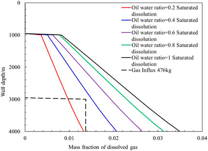
FIGURE 10. Mass fraction of dissolved gas in the drilling fluid with different oil–water ratio when gas is saturated.
As the well depth decreases, the wellbore pressure and temperature also decrease, and the gas saturation solubility in the wellbore decreases. When the mass fraction of intruded gas in the wellbore section exceeds the mass fraction in the wellbore at the time of gas saturation dissolution, free gas will appear in the wellbore. When the gas intrusion volume is 476 kg, the gas solubility in the wellbore is shown as the black-dashed line in the figure, and all the gas is dissolved in the drilling fluid in the wellbore with oil–water ratio of 0.4 and above. When the oil–water ratio of the drilling fluid is 0.2 and below, the mass fraction of gas intruded in the wellbore exceeds the mass fraction of dissolved gas in the drilling fluid at the time of gas saturation dissolution in the wellbore, and free gas will appear in the wellbore.
When gas dissolution is considered, the intruded gas is divided into two parts: transported gas and dissolved gas. The gas distribution characteristics in the wellbore when the intruded gas mass is 476 kg and the oil–water ratio of the drilling fluid is 0.2 and 0.1 are shown in Figure 11.

FIGURE 11. Gas distribution in wellbore under different oil–water ratio.
When the well depth is larger, the temperature and pressure at the bottom of the well are larger, the gas solubility in the drilling fluid is high, and all the gas is dissolved in the drilling fluid at the beginning of the overflow. The gas saturation solubility decreases during the drilling fluid rise, and the overflow gas will be desolvated to produce free gas. As the well depth decreases, both gas expansion and dissolved gas desolvation promote the increase of free gas volume fraction, and the free gas volume fraction grows faster after the free gas appears in the wellbore compared with when gas dissolution is not considered.
When there is no free gas in the wellbore, there is no gas suspension. According to the calculation results in the previous section, when the oil–water ratio of drilling fluid is small (<0.2), there is free gas in the wellbore. This section mainly analyzes the influence of gas suspension on the multiphase flow law in the wellbore after overflow without considering the small gas dissolution and oil–water ratio.
From Equation 35, we can calculate that the average radius of suspended gas bubbles under case well conditions is about 0.5128 mm and the gas suspension concentration is 0.0313. As the well depth decreases, the free gas density decreases, the average radius of individual suspended gas bubbles in the wellbore decreases and the gas suspension concentration increases. The gas distribution characteristics in the wellbore with a total overflow gas mass of 476 kg are shown in Figure 12. The volume fraction of free gas in the wellbore includes both transported gas and suspended gas, and the volume fraction of free gas is shown as the black-dashed line in the figure. The volume fraction of suspended gas in the wellbore varies slightly, and the suspended gas concentration in the wellbore of the overflow contaminated section increases from 0.0313 at the bottom of the well to 0.0318 at 3100 m. The fraction of transported gas at the bottom of the well is 0.0571, and the volume of transported gas increases during the upward transport. The magnitude of the abrupt change is reduced compared with that when gas suspension is not considered.
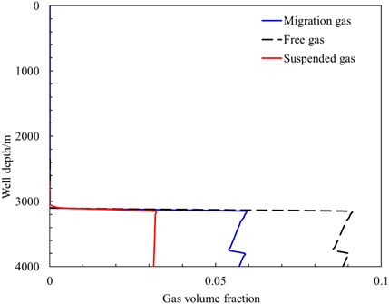
FIGURE 12. Gas distribution in wellbore when considering gas entrapment.
The suspended gas concentration in the wellbore is mainly affected by the drilling fluid yield stress, density, and gas phase density, where the gas phase density is influenced by the wellbore pressure and is related to the drilling fluid density and formation pressure. Among the aforementioned influencing factors, drilling fluid density, and yield stress are adjustable, while formation pressure and other factors are not adjustable. Assuming that the free gas density and volume fraction have the same distribution pattern as in Figure 12, the variation pattern of the suspended gas volume fraction in the wellbore at different densities when the drilling fluid yield stress is 4 Pa is shown in Figure 13A.

FIGURE 13. Distribution of suspended gas in wellbore.
With the increase of drilling fluid density, the density difference between gas and liquid also increases, which on the one hand reduces the average radius of suspended bubbles, on the other hand increases the buoyancy of suspended bubbles, which is more conducive to the increase of gas suspension concentration on the whole. When the density of the drilling fluid is 1000 kg m−3, the volume fraction of suspended gas at the bottom of the well is 0.0250. When the density of drilling fluid increases to 2000 kg m−3, then the concentration of suspended gas increases to 0.0428.
When the drilling fluid density is 1300 kg m−3, the gas suspension concentration in the wellbore under different yield stress is shown in Figure 13B. As the yield stress of drilling fluid increases, the volume fraction of suspended gas decreases. When the yield stress of the drilling fluid is 10 Pa, the volume fraction of suspended gas at the bottom of the well is 0.0081. When the yield stress decreases to 2 Pa, then the volume fraction of suspended gas increases to 0.0679. When the yield stress is reduced to 1 Pa, the allowable limit suspension concentration of gas is 0.1166. In the simulation calculation, all the invaded gas is suspended in the drilling fluid, and the volume fraction of suspended gas at the bottom of the well is 0.0884, as shown in the black curve in the figure. When the suspended gas increases with the drilling fluid, the wellbore pressure decreases, the total volume of free gas increases, and the volume fraction of suspended gas also increases. The volume fraction of suspended gas at the well depth of 3150 m increases to 0.0979.
The gas in the wellbore is preferentially dissolved in the drilling fluid, and the insoluble free gas is secondarily suspended in the drilling fluid. The gas exceeding the suspended concentration will slip and rise in the drilling fluid. Under the conditions of the example well, all the gas is dissolved in the drilling fluid, and free gas will appear when the oil–water ratio of the drilling fluid is less than 0.2. When the density of the drilling fluid is 1300 kg m−3, the yield stress is 4Pa, and the oil–water ratio is 0.2, the gas distribution characteristics in the wellbore when the total mass of invaded gas reaches 476 kg are shown in Figure 14A. Most of the gas is dissolved in the drilling fluid, and the integral number of free gas is small. The volume fraction of free gas at the bottom of the well is only 0.0025, which is far less than the limit suspended concentration of gas in the drilling fluid at the bottom of the well of 0.0313. All free gas exists in the form of suspended gas. During the increase of contaminated drilling fluid, the solubility of gas in the drilling fluid decreases, and the desolvated gas increases the volume fraction of free gas. When the gas front reaches the well depth of 3044 m, the volume fraction of free gas in the wellbore becomes 0.0211, which is less than the limit suspended concentration of gas in the well depth of 0.0318, that is, all free gases are suspended gases.
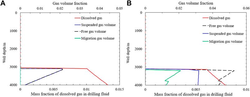
FIGURE 14. (A) Distribution of gas with oil–water ratio of 0.2. (B) Distribution of gas with oil–water ratio of 0.1.
Under the same drilling fluid density and yield stress conditions, the gas distribution characteristics in the wellbore when the total mass of intruded gas reaches 476 kg at the drilling fluid oil–water ratio of 0.1 are shown in Figure 14B. The volume fraction of free gas in the wellbore increased due to the decrease in the mass fraction of dissolved gas in the drilling fluid. Due to the small change in the volume fraction of suspended gas, most of the free gas precipitated from the drilling fluid existed in the form of transport gas, and the volume fraction of transport gas was 0.0210 at the well depth of 3040 m.
By analyzing the law of gas dissolution and suspension on the overflow in the wellbore after the overflow, it can be seen that after the occurrence of gas intrusion, all the intruded gas at the bottom of the well may be suspended in the drilling fluid and because there is no free gas, it is impossible to determine whether gas intrusion occurs by means such as mud pool increment. When the drilling fluid encounters a high-pressure gas intrusion section, the increase in vertical pressure can be used to determine whether the drilling encounters a high-pressure layer.
After gas intrusion shut-in, the drilling fluid stops circulating and the increase of free gas slip in the wellbore will cause the wellbore pressure to increase. When gas dissolution suspension is not considered, the pattern of pressure change at the bottom of the well after shut-in is shown in the blue line in Figure 15.
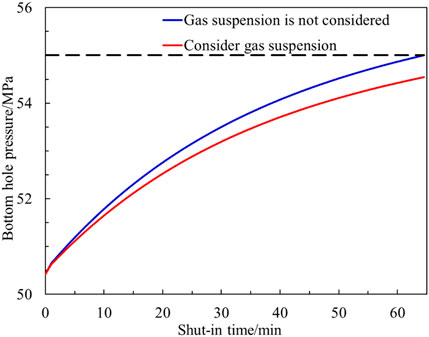
FIGURE 15. Change of bottom-hole pressure after shut-in.
On the one hand, the rising gas slip causes the pressure in the gas-bearing well section to increase, and on the other hand, the continuous intrusion of gas into the wellbore causes the compression of the existing gas volume in the wellbore, which also promotes the increase of the wellbore pressure. As the shut-in time increases, the wellbore pressure increases and the pressure difference between the formation and the bottom of the well gradually decreases, the amount of gas intruding into the wellbore after shut-in also gradually decreases, and the pressure increase in the wellbore gradually decreases. After 64.5 min of well shut-in, the pressure in the wellbore increased to 55 MPa, which was equal to the formation pressure, and the gas no longer continued to intrude.
As the shut-in time increases, the peak volume fraction of gas in the wellbore gradually decreases, with a peak volume fraction of 0.0827 after 10 min, 0.0730 after 30 min, and 0.070 after 60 min.
The gas distribution characteristics in the wellbore after shut in are shown in Figure 16. When the gas is dissolved in the wellbore, there is no free gas in the wellbore, and gas intrusion may exist when the vertical pressure value increases during the drilling process. After the well is shut-in, there is no gas slippage in the wellbore and the pressure at the bottom of the well remains unchanged because all the intruded gas is dissolved in the drilling fluid at the bottom of the wellbore. Continued gas intrusion causes gas solubility in the drilling fluid at the bottom of the well to reach saturation, after which free gas appears to enter the next well section and continues to dissolve into the drilling fluid. The pressure at the bottom of the well is always constant when the volume of the drilling fluid expands without considering the gas dissolution.
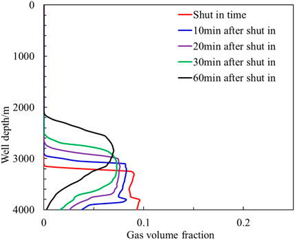
FIGURE 16. Distribution of gas after shut-in.
Without considering gas dissolution and the presence of gas suspension in the wellbore, the law of pressure change at the bottom of the well after shutdown is shown in the red line in Figure 15. The presence of suspended gas leads to a decrease in the volume fraction of transported gas in the wellbore and a small decrease in the velocity of transported gas compared to the absence of gas suspension, and the increase in wellbore pressure due to the rise in gas slip is reduced. The bottom-hole pressure was 51.65 MPa at 10 min shutdown time, increased to 53.19 MPa at 30 min shutdown time, and increased to 54.42 MPa after 1 hour shutdown. The presence of suspended gas after shutdown slowed the increase in wellbore pressure and increased the gas intrusion rate at the bottom-hole.
The gas distribution characteristics in the wellbore under different shut-in times are shown in Figure 17.
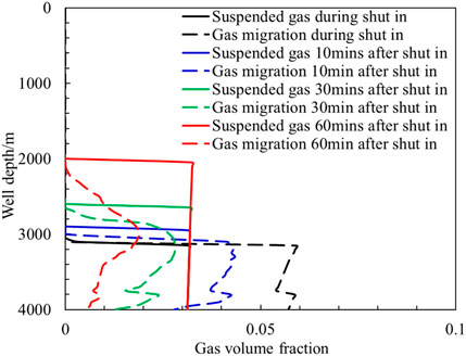
FIGURE 17. Distribution of gas after shut-in with considering of gas entrapment.
The free gas in the wellbore will be suspended after slipping and rising into the uncontaminated drilling fluid, resulting in the increase of the length of the well section with suspended gas. The longer is the shut-in time, the larger is the total volume of suspended gas. The gas in migration state gradually turns into the suspension state in the rising process, resulting in the rapid reduction of the volume fraction of migration gas in the wellbore. The peak volume fraction of migrating bodies in the wellbore decreases to 0.0436 after 10 min shut-in, 0.0280 after 30 min shut-in, and 0.0191 after 60 min shut-in.
With the increase of well shut-in time, the volume fraction of transported gas gradually changes from peak distribution to gentle distribution, and when the bottom pressure is less than the formation pressure, the volume fraction of transported gas in the wellbore will be infinitely close to the volume fraction of transported gas at the bottom. When the bottom pressure equals or exceeds the formation pressure, the formation gas will no longer intrude and the transported gas will gradually become zero from the bottom of the well, and the pressure at the bottom of the well will reach its peak after all the gas is suspended at the leading edge of the gas.
Regardless of gas dissolution and suspension, after the overflow reaches 2 m3, shut-in the well for 10 min and use the engineer method to kill the well. The variation law of riser pressure and casing pressure in the wellbore is shown in Figure 18. The density of kill fluid is 1410 kg m−3, the displacement is 15 m s−1, and the initial vertical pressure is 10.16 MPa. At 39 min, the weighted drilling fluid reached the bottom of the well, and the vertical pressure decreased to 6.24 MPa.
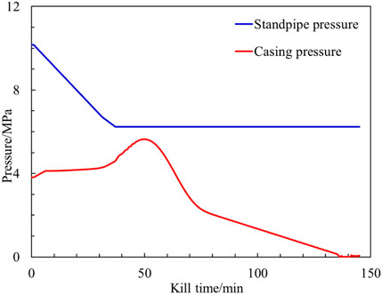
FIGURE 18. Change of stand pipe pressure and casing pressure during well killing.
The pressure in the wellbore was 3.82 MPa at the beginning of the well pressure, and the bottom pressure was still less than the formation pressure. After 6 min of well pressure, the pressure in the wellbore increased to 4.12 MPa, and the bottom-hole pressure was equal to the formation pressure, so the formation fluid was no longer intruding. The closer to the wellhead, the faster is the gas expansion rate and the greater is the casing pressure rise rate. After the gas is discharged from the throttle line, the effect of gas expansion on the increase of casing pressure decreases, and the pressure in the wellbore reaches the peak when the gas is discharged from the throttle line and the gas expansion in the wellbore has equal effect on the pressure, and the casing pressure reaches the peak value of 5.64 MPa at 50 min after the well is pressurized. The pressure in the casing gradually decreases, and the casing pressure drops to zero after the gas and the original drilling fluid are all discharged.
The gas distribution in the wellbore under different killing times is shown in Figure 19.
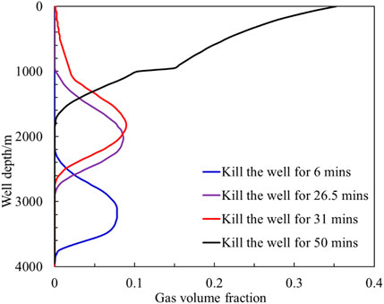
FIGURE 19. Distribution of gas during well killing.
With the increase of well killing time, the gas in the wellbore expands continuously in the rising process, and the length and porosity of the contaminated drilling fluid section in the wellbore increase. When killing the well for 6 min, the bottom-hole pressure is equal to the formation pressure, and then there is no gas intrusion at the bottom of the well, and the trailing edge of the gas rises from the bottom of the well. After killing the well for 26.5 min, the gas reaches the choke line at the front edge, and the migration speed of the gas in the choke pipe increases rapidly. After killing the well for 31 min, the gas begins to appear at the wellhead, and the volume fraction of the gas in the choke line increases continuously during the gas discharge process.
When gas dissolution is considered, most of the gas in the wellbore is dissolved in the drilling fluid after 10 min of shut-in, and a small amount of gas in the saturated dissolved well section slips off and rises in the wellbore in its own gas form. The distribution characteristics of dissolved gas in the wellbore at different moments are shown in Figure 20A. At the beginning of the well compression period, the gas continuously intruded during the shut-in period gradually reached saturation from the bottom of the well. After the start of well compression, the bottom-hole pressure increased and the gas in the wellbore no longer continued to intrude, and the dissolved gas increased with the original drilling fluid during the well compression process.
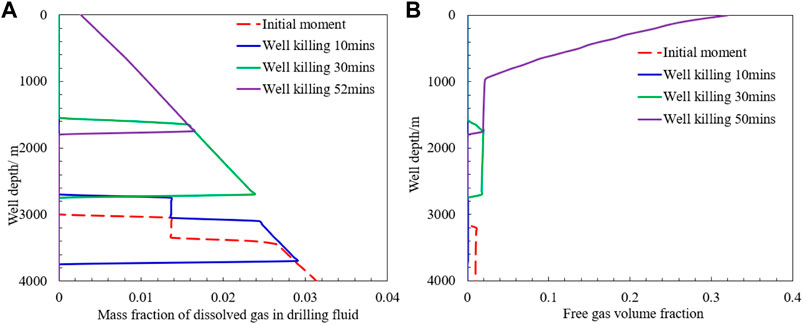
FIGURE 20. (A) Distribution of dissolved gas during the well killing. (B) Distribution of free gas during the well killing.
After 10 min of well pressure, the gas in the drilling fluid at the bottom of the contaminated drilling fluid section reached saturation dissolution. As the wellbore pressure increased, the saturation solubility of the gas in the wellbore also increased, and the gas mass fraction in the drilling fluid also increased, and the gas originally in the transport state also dissolved into the drilling fluid. As the original drilling fluid and the intruded gas increased in the wellbore, the dissolved gas saturation in the drilling fluid gradually decreased, and the dissolved gas mass fraction reached saturation and free gas began to desolvate and precipitate, which led to an increase in the length of the contaminated drilling fluid section in the wellbore. After 30 min of well pressure, the length of contaminated drilling fluid section in the wellbore increased from 900 m at the initial moment to 1100 m; 52 min after well pressure, the leading edge of dissolved gas reached the outlet of the throttle line.
The volume fraction of free gas in the wellbore at different pressure times is shown in Figure 20B. A small amount of free gas exists at the bottom of the well. The volume fraction of free gas at 10 min of well pressure (solid blue line) coincides with the vertical axis in the figure. As the contaminated drilling fluid increases during the well pressure process, the dissolved gas in the drilling fluid becomes supersaturated and then precipitates out. Near the leading edge of the gas, the sliding gas dissolves into the uncontaminated drilling fluid, the volume fraction of the gas decreases and the length of the contaminated drilling fluid section increases. After the gas enters the throttle line, the return rate is further accelerated, the gas solubility in the wellbore decreases significantly, and the free gas volume fraction increases sharply.
The law of pressure change in the wellbore after shut-in considering gas dissolution is shown in Figure 21. Compared with not considering gas dissolution, the peak pressure in the wellbore appears later, and the peak pressure increases slightly. The wellbore pressure reaches the peak value of 5.91 Pa after 71 min of well killing.
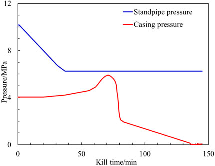
FIGURE 21. Change of stand pipe pressure and casing pressure during well killing.
When both gas dissolution and suspension are considered, the change law of dissolved gas mass fraction in the drilling fluid during well compression is the same as when only dissolved wellbore gas distribution is considered, but the growth rate of contaminated drilling fluid section length decreases, and the change law of suspended gas volume fraction in the wellbore at different shut-in moments is shown in Figure 22. At the initial moment of well pressure, the gas continuously invaded after well shut-in reached saturation in the drilling fluid and was suspended at the bottom of the wellbore, and the height of the leading edge of suspended gas in the wellbore was 3650 m. After 10 min of well pressure, all the gas was dissolved in the drilling fluid due to the increase in wellbore pressure, and there was no suspended gas in the wellbore. After 30 min of well pressure, the suspended gas section in the wellbore was 1700–2700 m. After 50 min of well shut-in, the contaminated drilling fluid entered the throttle line, and as the pressure decreased, the volume fraction of transported gas in the throttle line gradually increased and the volume fraction of suspended gas gradually decreased, and the volume fraction of suspended gas near the wellbore decreased rapidly.
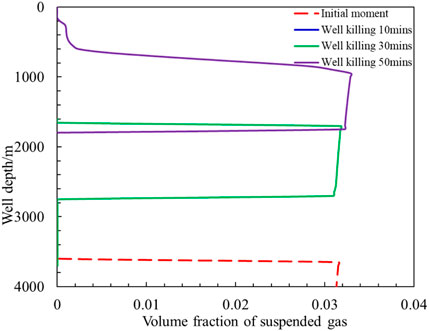
FIGURE 22. Distribution of entrapped gas during the well killing.
The variation pattern of casing pressure and riser pressure during the well compression process when gas dissolution and suspension are also considered is shown in Figure 23. Compared with considering gas dissolution only, gas suspension leads to a lower volume fraction of gas slipping up in the wellbore and a shorter gas slipping transport up distance, which leads to an increase in the time for gas to start exiting the throttle line during the well pressurization process. The casing pressure peaked at 5.55 MPa after 74 min of shut-in, and the peak casing pressure was reduced compared to that when only dissolution was considered, and the time to peak casing pressure increased.
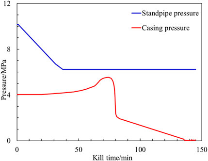
FIGURE 23. Change of stand pipe pressure and casing pressure during well killing.
This article simulates the multiphase flow pattern and pressure changes in the wellbore of an offshore well after gas intrusion using the prepared wellbore multiphase flow law and wellbore pressure simulation software. The effects of gas dissolution and suspension on the multiphase flow in the wellbore during the overflow simulation, well shut-in, and well compression were analyzed. The larger is the oil–water ratio of the drilling fluid, the larger is the mass fraction of dissolved gas in the drilling fluid, and all the intruded gas at the bottom of the well will be dissolved in the drilling fluid; when there is free gas in the wellbore, the higher is the drilling fluid density and the smaller is the yield stress (>1 Pa), the larger is the gas ultimate suspension concentration. When dissolved gas is present in the wellbore after gas intrusion shutdown, there is almost no change in wellbore pressure without free gas in the wellbore; when suspended and free gas is present in the wellbore, the wellbore pressure increases less rapidly after shutdown, and the volume fraction of free gas decreases if the shutdown time is longer, and eventually all gas will be suspended in the drilling fluid. During the pressure process, gas dissolution leads to an increase in peak pressure and peak time in the wellbore; gas suspension leads to a decrease in peak pressure and an increase in peak time in the wellbore.
The original contributions presented in the study are included in the article/Supplementary Material; further inquiries can be directed to the corresponding authors.
WZ: conceptualization, methodology, and software. XX: data curation and validation. CZ: visualization and investigation. YQ: supervision. KK: data curation. SP: software, writing–original draft. ZL: writing–review and editing. JZ: project administration.
The work was supported by the Guangdong Marine Economic Development (Six Marine Industries) Special Fund Project [GDNRC(2021)56], the CNPC’s Major Science and Technology Projects (ZD 2019-184-003), and the National Natural Science Foundation of China (51991363).
The authors declare that the research was conducted in the absence of any commercial or financial relationships that could be construed as a potential conflict of interest.
All claims expressed in this article are solely those of the authors and do not necessarily represent those of their affiliated organizations, or those of the publisher, the editors, and the reviewers. Any product that may be evaluated in this article, or claim that may be made by its manufacturer, is not guaranteed or endorsed by the publisher.
The Supplementary Material for this article can be found online at: https://www.frontiersin.org/articles/10.3389/feart.2022.993876/full#supplementary-material
Beris, A. N., Tsamopoulos, J. A., Armstrong, R. C., and Brown, R. A. (1985). Creeping motion of a sphere through a bingham plastic. J. Fluid Mech. 158 (1), 219–244. doi:10.1017/S0022112085002622
Dimakopoulos, Y., Pavlidis, M., and Tsamopoulos, J. (2013). Steady bubble rise in herschel–bulkley fluids and comparison of predictions via the augmented lagrangian method with those via the papanastasiou model. J. Newt. Fluid Mech. 200, 34–51. doi:10.1016/j.jnnfm.2012.10.012
Duan, W., Sun, B., and Deng, P. (2021). A wellbore pressure calculation method considering gas entrapment in wellbore shut-in condition[J]. J. China Univ. Petroleum Ed. Nat. Sci. 45 (5), 88–96. doi:10.3969/j.issn.1673-5005.2021.05.010
Dubash, N., and Frigaard, I. A. (2007). Propagation and stopping of air bubbles in Carbopol solutions. J. Newt. fluid Mech. 142 (1-3), 123–134. doi:10.1016/j.jnnfm.2006.06.006
Dubash, N., and Frigaard, I. (2004). Conditions for static bubbles in viscoplastic fluids. Phys. Fluids 16 (12), 4319–4330. doi:10.1063/1.1803391
Ettehadi, A., Lker, C., and Altun, G. (2022). Nonlinearity in large amplitude oscillatory shear of drilling fluid: a comparative study on the oil and water base muds behavior. J. Petroleum Sci. Eng. 208, 109536. doi:10.1016/j.petrol.2021.109536
Feng, J., Fu, J., Chen, P., and Xu, L. (2019). Investigation of methane/drilling mud phase behavior and its influence to hydrocarbon drilling activity. Energy Sci. Eng. 7 (4), 1280–1291. doi:10.1002/ese3.345
Fu, W., Chen, B., Zhang, K., Liu, J., Sun, X., Huang, B., et al. (2022a). Rheological behavior of hydrate slurry with xanthan gum and carboxmethylcellulose under high shear rate conditions. Energy fuels. 36 (6), 3169–3183. doi:10.1021/acs.energyfuels.1c04359
Fu, W., Wang, Z., Zhang, J., Cao, Y., and Sun, B. (2019). Investigation of rheological properties of methane hydrate slurry with carboxmethylcellulose. J. Petroleum Sci. Eng. 184, 106504. doi:10.1016/j.petrol.2019.106504
Fu, W., Yu, J., Xiao, Y., Wang, C., Huang, B., and Sun, B. (2022b). A pressure drop prediction model for hydrate slurry based on energy dissipation under turbulent flow condition. Fuel 311, 122188. doi:10.1016/j.fuel.2021.122188
Fu, W., Yu, J., Xu, Y., Wang, C., Huang, B., and Sun, B. (2022c). A pressure drop prediction model for hydrate slurry based on energy dissipation under laminar flow condition. SPE J. 27, 2257–2267. doi:10.2118/209586-PA
Hasan, A. R., Kabir, C. S., and Wang, X. (1998). Wellbore two-phase flow and heat transfer during transient testing. SPE J. 3 (02), 174–180. doi:10.2118/38946-pa
Ishii, M. (1977). One-dimensional drift-flux model and constitutive equations for relative motion between phases in various two-phase flow regimes (No. ANL-77-47). USA: Argonne National Lab., Ill.
Liu, H., Jin, Y., and Guo, B. (2021). Experimental study on the suspension amount of invasion gas in drilling fluid with yield stress. Geofluids, 1–10. doi:10.1155/2021/7225280
Manikonda, K., Hasan, A. R., Kaldirim, O., Rahmani, N., and Rahman, M. A. (2020). “Estimating swelling in oil-based mud due to gas kick dissolution,” in International conference on offshore mechanics and arctic engineering (American Society of Mechanical Engineers (ASME)), 84430, V011T11A039. doi:10.1115/OMAE2020-18115
Manikonda, K., Hasan, A. R., Kaldirim, O., Schubert, J. J., and Rahman, M. A. (2019). “Understanding gas kick behavior in water and oil-based drilling fluids,” in SPE Kuwait oil & gas show and conference (Kuwait City, Kuwait: OnePetro). doi:10.2118/198069-MS
O'Bryan, P. L. (1988). Well control problems associated with gas solubility in oil-based drilling fluids. Louisiana, United States: Louisiana State University and Agricultural & Mechanical College. Doctoral dissertation.
O'Bryan, P. L., and Bourgoyne, A. T. (1990). Swelling of oil-based drilling fluids resulting from dissolved gas. SPE Drill. Eng. 5 (02), 149–155. doi:10.2118/16676-pa
Pan, S., Wang, Z., and Sun, B. (2022). A new model for predicting the maximum gas entrapment concentration in a yield stress fluid. SPE J. 27 (02), 1049–1063. doi:10.2118/208600-PA
Samson, G., Phelipot-Mardelé, A., Lanos, C., and Pierre, A. (2017). Quasi-static bubble in a yield stress fluid: Elasto-plastic model. Rheol. Acta 56 (5), 431–443. doi:10.1007/s00397-017-1007-2
Sikorski, D., Tabuteau, H., and de Bruyn, J. R. (2009). Motion and shape of bubbles rising through a yield-stress fluid. J. Newt. Fluid Mech. 159 (1-3), 10–16. doi:10.1016/j.jnnfm.2008.11.011
Sleiti, A. K., Takalkar, G., El-Naas, M. H., Hasan, A. R., and Rahman, M. A. (2020). Early gas kick detection in vertical wells via transient multiphase flow modelling: A review. J. Nat. Gas Sci. Eng. 80, 103391. doi:10.1016/j.jngse.2020.103391
Sun, B., Sun, X., et al. Sun, B., Sun, X., Wang, Z., and Chen, Y. (2017). Effects of phase transition on gas kick migration in deepwater horizontal drillingEffects of phase transition on gas kick migration in deepwater horizontal drilling. J. Nat. Gas Sci. Eng. Nat. Gas Sci. Eng. 4646, 710710–729729. doi:10.1016/j.jngse.2017.09.001
Thomas, D. C., Lea, J. F., and Turek, E. A. (1984). Gas solubility in oil-based drilling fluids: Effects on kick detection. J. petroleum Technol. 36 (06), 959–968. doi:10.2118/11115-pa
Tsamopoulos, J., Dimakopoulos, Y., Chatzidai, N., Karapetsas, G., and Pavlidis, M. (2008). Steady bubble rise and deformation in Newtonian and viscoplastic fluids and conditions for bubble entrapment. J. Fluid Mech. 601, 123–164. doi:10.1017/S0022112008000517
Wang, Z. Y., Sun, B. J., Cheng, H. Q., and Gao, Y. H. (2008). Prediction of gas hydrate formation region in the wellbore of deepwater drilling. Petroleum Explor. Dev. 35 (6), 731–735. doi:10.1016/S1876-3804(09)60103-8
Werner, B., Myrseth, V., and Saasen, A. (2017). Viscoelastic properties of drilling fluids and their influence on cuttings transport. J. Petroleum Sci. Eng. 156, 845–851. doi:10.1016/j.petrol.2017.06.063
Keywords: gas dissolution, gas suspension, multiphase flow model, wellbore pressure calculation, drilling shaft
Citation: Zhang W, Xue X, Zhang C, Qu Y, Ke K, Pan S, Zeqin Li and Zhang J (2022) A drilling wellbore pressure calculation model considering the effect of gas dissolution and suspension. Front. Earth Sci. 10:993876. doi: 10.3389/feart.2022.993876
Received: 15 July 2022; Accepted: 10 August 2022;
Published: 27 September 2022.
Edited by:
Ali Abedini, Urmia University, IranReviewed by:
Maryam Khosravi, Isfahan University of Technology, IranCopyright © 2022 Zhang, Xue, Zhang, Qu, Ke, Pan, Zeqin Li and Zhang. This is an open-access article distributed under the terms of the Creative Commons Attribution License (CC BY). The use, distribution or reproduction in other forums is permitted, provided the original author(s) and the copyright owner(s) are credited and that the original publication in this journal is cited, in accordance with accepted academic practice. No use, distribution or reproduction is permitted which does not comply with these terms.
*Correspondence: Shaowei Pan, cGFuc2h3ODEzMjAuc3JpcGVAc2lub3BlYy5jb20=
Disclaimer: All claims expressed in this article are solely those of the authors and do not necessarily represent those of their affiliated organizations, or those of the publisher, the editors and the reviewers. Any product that may be evaluated in this article or claim that may be made by its manufacturer is not guaranteed or endorsed by the publisher.
Research integrity at Frontiers
Learn more about the work of our research integrity team to safeguard the quality of each article we publish.