 Baizhi Wu1
 Xin Sun
94% of researchers rate our articles as excellent or good
Learn more about the work of our research integrity team to safeguard the quality of each article we publish.
Find out more
ORIGINAL RESEARCH article
Front. Earth Sci., 25 August 2022
Sec. Economic Geology
Volume 10 - 2022 | https://doi.org/10.3389/feart.2022.990963
This article is part of the Research TopicAdvances in Multi-Physics Multi-Component Fluid Transport and Multi-Scale Geophysical Modeling in Unconventional Oil and Gas Reservoir - Volume IIView all 4 articles
Hydraulic fracturing is one of the most commonly used processes of stimulating oil and gas wells to improve the production in low permeability reservoirs or damaged wells. In response to the serious water waste caused by the flowback fluid after the fracturing operation and the huge environmental pressure, a novel CO2 sensitive and recyclable viscoelastic fracturing fluid was developed. This CO2 sensitive property allows fracturing fluids to be recycled. The system consists of viscoelastic surfactants called fatty methyl ester sulfonates (FMES), triethylenetetramine and NaCl. The system shows a strong sensitivity to CO2. When the system is repeatedly contacted and separated from CO2, the viscosity rises and falls rapidly and regularly. The experiments of viscoelasticity, shear resistance and microstructure confirmed that the increasing viscosity of the system after contacting with CO2 was caused by the formation of viscoelastic fluid. When the system leak-off into the formation matrix, the microstructure of the system will be rapidly destroyed under the action of hydrocarbons, and the viscosity will drop to 1.225 mPa·s. Low viscosity after destroying reduces the retention of the system in the formation, resulting in formation damage rate of less than 35%. This research not only provides high-performance, low-cost fracturing fluids, but also provides new insights for the recovery and utilization of fracturing fluids.
Since the 21st century, unconventional reservoir has become one of the most important fields of oil and gas exploration and development (Montgomery and Smith, 2010; Barati and Liang, 2014; Zhang et al., 2015a). A large amount of practical experience has shown that “hydraulic fracturing is an irreplaceable technology for the exploitation of unconventional oil and gas reservoirs”, and it is also a key technology for economic and effective exploitation (Clark, 1949; Almuntasheri, 2014a; Fan et al., 2020). This is because hydraulic fracturing can provide a large number of fractures in the reservoir to serve as high-speed oil and gas seepage channels. In the process of hydraulic fracturing, the selection of efficient and economical fracturing fluid system is of great significance to ensure the fracturing effect. The ideal fracturing fluid should have high viscoelasticity, low fluid loss, good sand carrying, easy gel breaking and backflow, low core damage and low cost (Lv et al., 2015; Yin et al., 2019).
At present, the widely used water-based fracturing fluids mainly use polymer or viscoelastic surfactant as thickener. Compared with polymer fracturing fluids, viscoelastic surfactant (VES) fracturing fluids have many advantages: no crosslinking agent is required, no water-insoluble materials, little damage to the formation, and easy flowback after gel breaking (Liu et al., 2009; Wang et al., 2017; Dan et al., 2020). However, VES fracturing fluids do not form a filter cake on the fracture surface, so it has a high leak-off rate in the formation (Almuntasheri, 2014b). Some researchers set the upper limit of formation permeability applicable to VES fracturing fluid to 100 mD (Sullivan, 2006).
Although VES fracturing fluid has excellent performance, its treatment after flowback is a serious problem due to the large amount of fracturing fluid and the presence of a variety of chemical agents (Jr et al., 2003; Du et al., 2011; Li et al., 2014). To meet the wastewater discharge indicators of various countries, oil fields and service companies need to spend a lot of costs (including equipment, manpower, time, etc.) for the treatment of flowback liquid.
Therefore, it is necessary to construct a recyclable viscoelastic fracturing fluid. This fluid not only inherits the benefits of viscoelastic fracturing fluids, but also dramatically reduces the cost of fracturing and wastewater treatment through the reuse of backflow fluids. The key of recyclable fracturing fluid lies in its controllable viscosity change. In other words, after the fracturing fluid flows back to the ground, its viscosity can be raised again by simple treatment. Series of studies found that some of the CO2 sensitive materials have the potential to build a recycled fracturing fluid (Wu et al., 2018a; Wu et al., 2018b; Zhao et al., 2018). In the development of fracturing fluids, a good CO2 sensitive material can react with CO2 quickly, resulting in a rapid increase in system viscosity. When the system is heated or exposed to a large number of other gases, the viscosity of the system will decrease due to the escape of CO2. This means that in the actual fracturing operation, the CO2 in the fracturing fluid will escape due to the continuous high temperature of the formation or the action of the gas, resulting in a decrease in the viscosity of the system. When the fracturing fluid flows back to the ground, it can be simply collected and processed and then re-introduced with CO2 to increase its viscosity, thereby realizing the reuse of the fracturing fluid.
During 2013 to 2015, Zhang et al. reported a long-chain tertiary amine surfactant solution that does not require the addition of counter-ions (Zhang et al., 2013a; Zhang et al., 2013b; Zhang and Feng, 2015). When CO2 is injected into the system, it is found that the viscosity of the system increases from 2 mPa s to more than 105 mPa s, and the system can be restored to its initial state by air or heating. And after more than three cycles, the performance of the system is basically unchanged. These studies show the possibility of building recyclable viscoelastic fracturing fluid by introducing CO2. In 2018, Wu et al. synthesized a CO2 responsive surfactant, Erucamidopropyl Dimethylamine (EA), and applied it to the development of fracturing fluids for the first time (Wu et al., 2018b). Results showed this fracturing fluid has a good CO2-responsiveness, switchable viscoelastic performance, high shear tolerance, and low core damage. However, the solubility of the surfactant used in Wu’s system decreases as the CO2 escapes in the formation, leading to partial precipitation from the liquid. This characteristic is not conducive to the recovery of surfactant after fracturing fluid flowback.
During this study, we first constructed a CO2 sensitive fracturing fluid using viscoelastic surfactants, small molecular amines and inorganic salts through extensive experiments. A series of properties such as temperature resistance, shear resistance, rheological property, recycling property, proppant suspension property, leak-off property and formation damage property were evaluated. In addition, the microstructure of the fluid is studied to explain the main mechanism of viscoelasticity of the system. This research not only provides high-performance, low-cost hydraulic fluids, but also provides new insights for the recovery and utilization of fracturing fluids.
The surface of rock is mostly negatively charged, which will lead to a large number of cationic molecules on the surface adsorption and retention, resulting in the waste of working fluid in the formation. Therefore, in order to maximize the recycling of fracturing fluid, we introduced a non-ionic anionic viscoelastic surfactant named fatty methyl ester sulfonates (FMES). The chemical structure of FMES was shown in Figure 1.
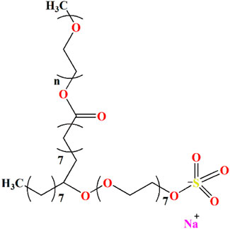
FIGURE 1. Chemical structure of FMES.
We employed four small molecule amines and investigated their CO2 sensitivity and their viscosivity when mixed with surfactants. The small molecules amines used in this research are diethylenetriamine, triethylenetetramine, tetrethylenepentamine and pentethylenehexamine.
The oil saturated cores were used for core permeability regaining test. The crude oil used for oil saturation was collected from Jimsar block, Zhundong Oilfield, Xinjiang, China. The crude oil was centrifuged and filtered through a 5 μm Millipore filter to remove water, solids, and other deposits prior to use, respectively (Shariatpanahi et al., 2010). According to the actual viscosity of underground oil, the experimental oil with a density of 0.8047 g/cm3 and a viscosity of 5.2 mPa·s at 20°C was prepared by mixing crude oil with aviation kerosene in definite proportions. The mixed oil was used in this study.
Several low permeability cores were employed in the leak-off characteristic test and core permeability regaining test. All the core samples were well cemented sandstone from Chang 7 block of Ordos basin in China, with 2.5 cm in diameter and 5 cm in length. The basic data of the core samples are listed in Table 1. The permeability shown in Table 1 is the nitrogen gas permeability. The cores L-40-20-1, L-14-2-1, and L-20-1-1 were used for leak-off characteristic test, while the remaining cores were used for permeability regaining test.
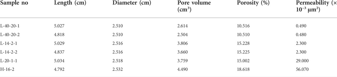
TABLE 1. Basic parameters of core samples.
First, 60 mmol/L of FMES were dissolved completely in deionized water individually. Next, four kinds of CO2 sensitizers were injected into the surfactant solution. And we also added a certain amount of NaCl to the system. After the solution was fully dissolved by stirring, sufficient amount of CO2 was slowly injected into the system. Finally, the samples were placed in a thermostat water bath at 60°C for 24 h to remove all air bubbles.
Hakke Mars 60 rheometer (Hakke, Germany) was employed to test the theological property of the fracturing fluid. In order to prevent the escape of CO2 during the high temperature test, we use the matching sealed measuring cup to conduct the rheological test. Before testing, the sample needs to be stable at a specific temperature for at least 24 h (Dai et al., 2017; Wang et al., 2017).
Various permeability core samples L-40-20-1, L-14-2-1, and L-20-1-1 were employed to take the leak-off experiment. The specific steps of the fluid leak-off experiment were carried out in accordance with the Chinese oil and gas industry standards (C.N.E.A., 2016).
(1) The core samples are cleaned and dried to measure the porosity.
(2) The core samples are saturated by 4% ammonium chloride aqueous solution.
(3) The core samples are placed in a core holder, and flooded with 4% ammonium chloride solution at 0.5 ml/min. The stable flooding pressure is recorded and used to calculate the initial core permeability. The core flooding setup is shown in Figure 2.
(4) The fracturing fluid system is injected into the core sample at a constant pressure of 6.895 MPa. The volume of liquid produced at the outlet at different times is recorded to calculate the leakage coefficient by the following formula (Sun et al., 2019).
Where Q denotes the leak-off rate, cm3/s; V is the leak-off fluid volume, cm3; T denotes the leak-off time, min.
Where μ represents the viscosity of filtrate, mPa·s; k is the permeability of core sample, μm2; A is the cross sectional area of core sample, cm2; Δp denotes the pressure difference between core ends, MPa; Q is the leak-off rate, cm3/s and L represents the length of core sample, cm.
Where C is the leak-off coefficient of fracturing fluid, m/s1/2; k denotes the permeability of core sample, m2; ϕ is the porosity of core sample; Δp represents the pressure difference between core ends, Pa and μ is the viscosity of filtrate, Pa·s.
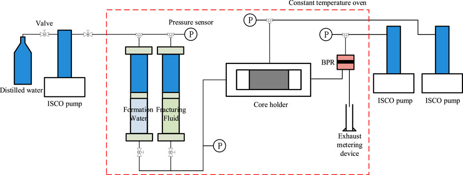
FIGURE 2. Core flooding system, here BPR denotes back-pressure regulator.
The procedure of core permeability regaining test is similar to leak-off experiment.
(1) The core sample is cleaned and dried first, and then the porosity of the sample is measured.
(2) The core samples are saturated by crude oil. It should be noted that due to the low permeability, the core should be saturated with the vacuum pressurization method.
(3) Same method as leak-off experiment step (3) is employed to test the initial permeability of core samples, recorded as K1. Here, crude oil is chosen as the flooding fluid instead of 4% ammonium chloride solution.
(4) The fracturing fluid is injected into the core in the opposite direction with a constant pressure difference of 1 MPa. This process is maintained for 36 min.
(5) The valves at both ends of the core holder are closed and kept for 120 min to allow the fracturing fluid to fully diffuse and react in the core samples.
(6) Same method is employed as step (3) to measure the permeability after core damage by fracturing fluid and recorded as K2. The formulas of permeability regain and damage ratio are as follows (Sun et al., 2019),
Where Krg denotes the permeability regain; ηd represents the permeability damage ratio; K1 is the initial permeability and K2 represents the permeability after core damage by fracturing fluid, ×10−3 μm2.
Theoretically, diethylenetriamine, triethylenetetramine, tetrethylenepentamine and pentethylenehexamine can all react with CO2(Jessop et al., 2012; Zhang et al., 2015b). Through the protonation of CO2, positively charged ammonium ions are formed. Ammonium ions can further interact with negatively charged FMES to allow the surfactant to self-assemble into wormlike micelles. In order to explore the viscosification ability of the systems formed by different types of small molecules amines, we tested the viscosity data of each system at room temperature (25°C). The detailed viscosity data after adding positive ion was shown in Figure 3.

FIGURE 3. System viscosity for different kinds of amine (60 mmol/L FMES), (A) low amine concentration (B) high amine concentration.
From Figure 3, it can be clearly seen that the type and concentration of small molecule amines have a significant impact on the system viscosity. At low concentration (lower than 180 mmol/L), with the increase of amine, the overall viscosity of the system shows an upward trend. However, when the amine concentration exceeds 1200 mmol/L-1500 mmol/L, the viscosity of the system will decrease to some extent. This is because after CO2 injection, small molecule amines are protonated to form ammonium ions. Ammonium ions will compress the electric double layer structure of the surfactant head base, so that the electrostatic repulsion on the surface of the head base is effectively shielded. At this time, the spherical micelles of the surfactant will gradually turn into worm-like micelles. These worm-like micelles are entangled with each other to form a three-dimensional structure, which makes the system viscoelastic on a macroscopic scale.
In Figure 3A, it can be seen that the sensitivity of different amine systems to CO2 is significantly different. Triethylenetetramine and pentethylenehexamine are the most sensitive to CO2. When the concentration is 20 mmol/L, the viscosity of the system increases significantly. The sensitivity of tetrethylenepentamine was slightly worse than the former two, and the viscosity of the system increased significantly at 30 mmol/L. However, diethylenetriamine is the least sensitive to CO2, and the change of system concentration will only be detected when the concentration reaches 1,200 mmol/L. This is because a single diethylenetriamine molecule has the least number of amine groups compared to the other three amines. Accordingly, a single diethylenetriamine molecule reacts with CO2 to form the lowest number of ammonium ions, so more molecules are required to form wormlike micelles. The addition of large amounts of diethylenetriamine is not appropriate for field application cost consideration, so we focus on the analysis of the other three amines.
When the amine concentration was 30 mmol/L, the highest viscosity of triethylenetetramine system was 1,217.4 mPa·s. While the viscosity of tetrethylenepentamine and pentethylenehexamine systems is 454.9 mPa·s and 457.9 mPa·s, respectively. When the concentration increases from 20 mmol/L to 180 mmol/L gradually, the viscosity of the triethylenetetramine system still has a dominant advantage over the other two. Moreover, it can be seen that when the concentration is 60 mmol/L, the viscosity of tetrethylenepentamine and pentethylenehexamine system decreases sharply, which reflects the instability of the viscosity increasing ability of these two amines. Therefore, we choose triethylenetetramine as the CO2 sensitive agent of the system.
As Figure 3A shown, the viscosity of the triethylenetetramine system remains between 1,200 mPa·s and 1,300 mPa·s at low concentrations. In order to further improve the viscosity and CO2 sensitivity of the system, and reduce the amount of triethylamine and system cost, we chose to add some cations to the system. In common cations, the radius of Na+ is smaller than that of K+. The smaller the ionic radius, the easier it is to adsorb around the polar groups, and more effectively shield the electrostatic repulsion (Mu and Li, 2001; Mu et al., 2002). Based on the performance-first principle, Na+ was chose as the counter ion in the fracturing fluid system. First, we detected the effect of NaCl concentrations on the system viscosity in the surfactant solution without triethylenetetramine, and the results were shown in Figure 4.
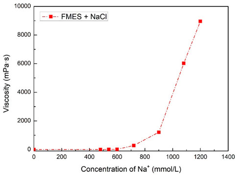
FIGURE 4. System viscosity for different concentration of Na+ without triethylenetetramine (60 mmol/L FMES).
As Figure 4 shown, the concentration of Na+ has a great impact on system viscosity. When the Na+ concentration reached 1,200 mmol/L, the viscosity of the system was 8,954.3 mPa·s, which far exceeded the viscosity of the surfactant and triethylenetetramine system in Figure 3. This effectively proves that adding Na+ can improve the viscosity of the system. However, considering the CO2 sensitivity of the system, we cannot add too much Na+. Our method here is to refer to the general technical specifications of fracturing fluids, make sure that the system is just lower than the gluing standard under the appropriate Na+ concentration, that is, 20.0 mPa·s. According to the results, the system viscosity with 540 mmol/L Na+ is 9.0 mPa·s, while the viscosity of 20.4 mPa·s with 600 mmol/L Na+. Therefore, we select the optimized concentration of Na+ is 540 mmol/L.
Then, we re-added different concentrations of triethylenetetramine to the 60 mmol/L surfactant and the 540 mmol/L NaCl system, respectively, and tested their viscosities. This has two purposes. On the one hand, we can verify whether the addition of Na+ increases the viscosity and CO2 sensitivity of the system as we expected. On the other hand, we can further optimize the concentration of triethylenetetramine in the system. The results were shown in Figure 5.
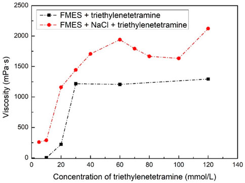
FIGURE 5. System viscosity for different concentration of triethylenetetramine with and without NaCl (60 mmol/L of FMES and 540 mmol/L Na+).
By comparing the two dotted lines in Figure 5, we can first find that the viscosity of the system with Na+ is better than that without Na+ at the same triethylenetetramine concentration. This proves that the addition of Na+ can indeed enhance the viscosification ability of the system. In addition, we can see that after CO2 injection, the viscosity of system with 5 mmol/L of triethylenetetramine and Na+ is even higher than system with 10 mmol/L of triethylenetetramine without Na+. This suggests that Na+ does increase the CO2 sensitivity of the system, as we expected. Furthermore, in the system of FMES + NaCl + triethylenetetramine, it can be seen that with the increase of triethylenetetramine concentration, the viscosity of the system gradually increases, reaching a peak of 1940.3 mPa·s at 60 mmol/L. When the concentration exceeds 60 mmol/L, the viscosity of the system decreases slightly. After the concentration reached 120 mmol/L, the viscosity increased back to 2,122.5 mPa·s. However, for the consideration of dosage and cost, we finally chose the formula of the system as 60 mmol/L FMES + 540 mmol/L NaCl + 60 mmol/L triethylenetetramine.
Proppant supports and migrates more efficiently in the elastic zone of a viscoelastic fracturing fluid than in the viscous zone (Harris et al., 2005). Figure 6 shows the viscoelasticity of the fracturing fluid system as the oscillation frequency. In the figure, G′ is the storage modulus, which represents the elasticity property of the system. Correspondingly, G″ is loss modulus, which represents the viscous property of the system. It can be seen that fracturing fluid system is characterized as liquid phase as G″ is greater than G′ at low oscillation frequency (Wu et al., 2018b). The transport of proppant depends on the viscosity characteristics of the system in this case. At high oscillation frequency, the storage modulus G′ is greater than the loss modulus G″, and the system exhibits solid phase properties, and the transport of proppant depends on the elastic characteristics of the system (Rehage and Hoffmann, 1988; Zhao et al., 2019). When the oscillation frequency is 1.60 Hz, the system storage modulus G′ is equal to the loss modulus G″, and the reciprocal of the oscillation frequency is referred to as the relaxation time, which is 0.63 s. In addition, at higher oscillation frequencies, the storage modulus G′ is basically unchanged, while the loss modulus G″ decreases first and then increases again with the increase of frequency. This phenomenon is consistent with Maxwell model and is one of the main characteristics of viscoelastic fluids composed of wormlike micelles (Granek and Cates, 1992).
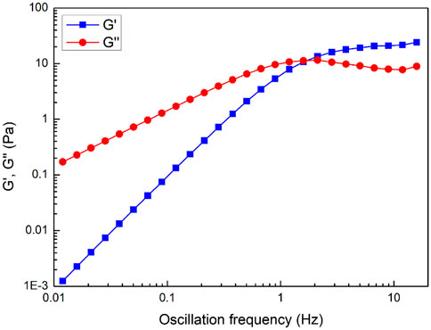
FIGURE 6. Storage and loss modulus (G′ & G″) as a function of oscillation frequency for fracturing fluid system.
Due to the geothermal gradient, the fracturing fluid usually faces the challenge of high temperature after being injected into the reservoir. Generally speaking, high temperature will destroy the three-dimensional structure of the worm-like micelles, thereby reducing the viscoelasticity of the fracturing fluid, which directly affects its sand-carrying capacity. During the test, in order to prevent the evaporation of liquid and the overflow of CO2 under high temperature for a long time, we put the system in a 5 MPa CO2 sealed environment for measurement. The shear rate was stable at 170 s−1. The detailed data was shown in Figure 7.
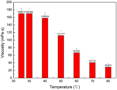
FIGURE 7. System viscosity in different temperatures.
From Figure 7, it can be seen that with the increase of temperature, the system viscosity continues to decrease. At room temperature (25°C) and 30°C, the viscosity is around 170 mPa·s. When the temperature reached to 40°C, the viscosity decreased to 158.024 mPa·s. Afterwards, with the increase of temperature, the system viscosity would be decrease to 28.974 mPa·s at 80°C. According to the general technical specifications of fracturing fluids (C.N.D.R.C, 2008), the viscosity of viscoelastic fracturing fluid should be higher than 20 mPa·s at the shear rate of 170 s−1. As Figure 6 shown, the system viscosity meets the requirements at temperatures of 80°C or below. That means the systems we developed can withstand temperatures of 80°C or even more. There are two points to be noted here. Since the formation temperature of the target formation (Chang 7 block, Ordos basin) is 70°C, the temperature resistance of the system meets the requirements of the target formation.
In the fracturing process, in order to form a high pressure zone near the well in a short time, the fracturing fluid is usually injected into the formation at an extremely high rate. Therefore, the fracturing fluid in the wellbore suffers from extremely high shear rates. For polymer fracturing fluids, the macromolecular chains will break during high-speed shear, thereby permanently reducing the viscosity of the fracturing fluid. The viscoelastic surfactant fracturing fluid is formed by self-assembly of small molecules. Although the viscoelasticity will be reduced at high shear rates, when the shear rate is reduced, small molecules can reassemble to restore viscoelasticity. (Acharya and Kunieda, 2006; Dreiss, 2007). Here, we measured the viscosity of the system at a shear rate of 170 s−1 and 510 s−1. The results are shown in Figure 8.
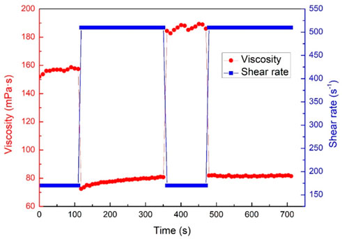
FIGURE 8. System viscosity with different shear rate.
According to Figure 8, when the initial shear rate is 170 s−1, the viscosity of the system is 156.3 mPa·s. As the shear rate rose to 510 s−1, the system viscosity increased gradually and on average 78.1 mPa·s. While the shear rate drops to 170 s−1 again, the system viscosity reached to 186.6 mPa·s. Finally, the shear rate rose to 510 s−1, the system viscosity was stable at 81.6 mPa·s. The data show that the system will not be destroyed due to the high shear rate, but will cause a slight increase in viscosity. In conclusion, this fracturing fluid has a remarkable self-repairability.
The realization of fracturing fluid recycling is of great significance to control construction cost, reduce water resource waste and environmental pollution. This is also one of our original intentions for this research. In order to achieve this goal, we selected the type of CO2 sensitizer and further enhanced the degree of CO2 sensitivity of the system by adding inorganic salts. In theory, when CO2 is injected into the system, protonation occurs, which causes nonionic amine to become positively charged ammonium ions, and then electrostatic shielding occurs to form wormlike micelles. However, after N2 is introduced, CO2 escapes from the system, and ammonium ions in the fracturing fluid are deprotonated to form nonionic amine. Micellar structure is destroyed and viscosity rapidly decreases. When CO2 is injected again, and protonation makes small molecule amine form ammonium ions again, thus building micelle network structure and forming highly viscous fracturing fluid. We carried out specific experiments based on theoretical analysis, and the results are shown in Figure 9. From the picture, it can be found that after alternating CO2 and N2, the viscosity of the system showed repetitive rise and fall. This shows that our system has nice recyclable performance.
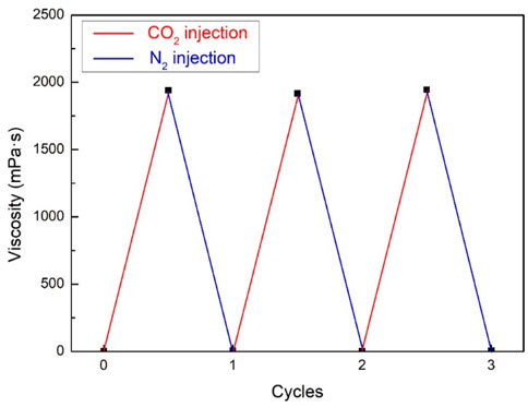
FIGURE 9. Viscosity of system after circulating into CO2 and N2.
In the early stages of fracture formation, leak-off of fracturing fluid through the formation slows down the rate of pressure increase and delays the onset of rock fracture. In addition, leak-off will cause the fracturing fluid to enter the reservoir and have a physical-chemical reaction with the reservoir, leading to changes in the physical properties of the reservoir. Polymer fracturing fluid usually forms a filter cake on the rock surface, thereby delaying or even preventing subsequent fluid loss. Since the clean fracturing fluid is composed of small molecules surfactant, it will not form a filter cake, that is, the fluid loss coefficient is constant. (Barati and Liang, 2014). The detailed experimental parameters and data was listed in Table 2.
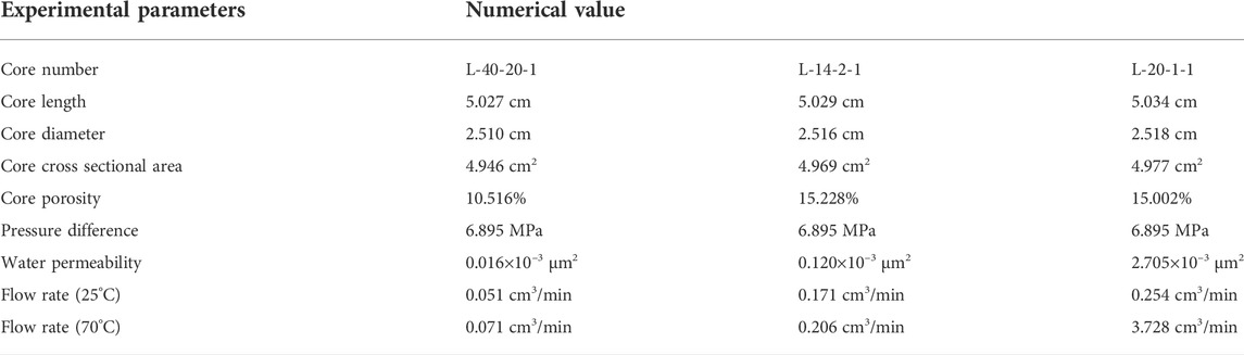
TABLE 2. Leak-off experimental parameters.
In this research, the filtration volume and time show a linear relationship, and the fluid loss coefficient is constant, which is consistent with the theory that clean fracturing fluid will not form filter cake. Through combining the data in Table 2 and the related formulas of Section 2.2.3, the leak-off coefficient of fracturing fluid can be finally computed. According to the results, the leak-off coefficient of L-40-20-1 at 25°C is 6.740 × 10⁻⁵ m/s1/2 and 8.006 × 10⁻⁵ m/s1/2 at 70°C, while L-14-2-1 is 1.495 × 10⁻⁴ m/s1/2 at 25°C and 1.619 × 10⁻⁴ m/s1/2 at 70°C, L-20-1-1 is 1.785 × 10⁻⁴ m/s1/2 at 25°C and 6.864 × 10⁻⁴ m/s1/2 at 70°C.
As we mentioned above, fracturing fluids have sand-carrying function and therefore usually have a certain viscosity. If these fracturing fluids maintain their initial viscosity after entering the formation, they will be difficult to flowback out of the formation and cause significant damage to the formation’s permeability. Therefore, the gel breaking performance of the fracturing fluid is directly related to the subsequent crude oil production. Based on this situation, the viscosity of breaking liquid was measured to evaluate the breaking property through the steady shear rheology test in 25°C, which was shown in Figure 10. During the test, 10% of kerosene was employed as the breaker.
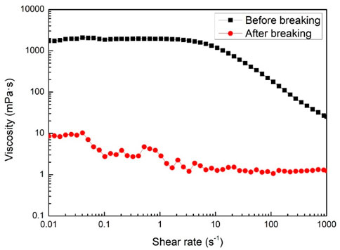
FIGURE 10. System viscosity change before and after breaking.
From Figure 10, the viscosity of the fracturing fluid dropped drastically after adding the breaker, from the initial 1940.275 mPa·s to 1.225 mPa·s. The viscosity of the gel breaking fluid meets the specification of the general technical specifications of fracturing fluids (C.N.D.R.C, 2008) (the viscosity of breaking liquid should be lower than 5 mPa·s).
After fracturing fluid leak-off to the formation matrix, it will be adsorbed and retained on the pore surface through microscopic forces, which will narrow or even block the subsequent fluid seepage channels. Therefore, the change of fracturing fluid permeability after dynamic fluid loss has important reference significance for oil and gas production after fracturing construction.
From Table 3, three low permeability cores both showed damage after filtration. According to the general technical specifications of fracturing fluids (C.N.D.R.C, 2008), the dynamic filtration damage of viscoelastic fracturing fluid should be lower than 40%, which means this fracturing fluid obviously met the standards. In order to further explore the causes of damage caused by fracturing fluid to the core, we observed the micro morphology of the core before and after the damage, as shown in Figure 11.
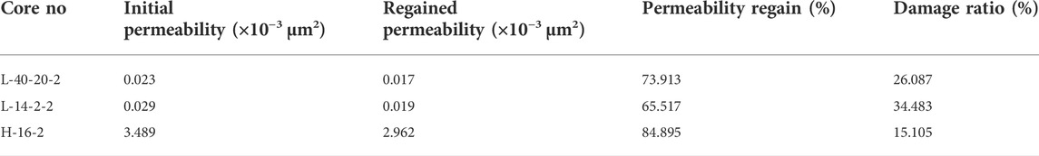
TABLE 3. Core permeability regaining after fracturing fluid treatment.
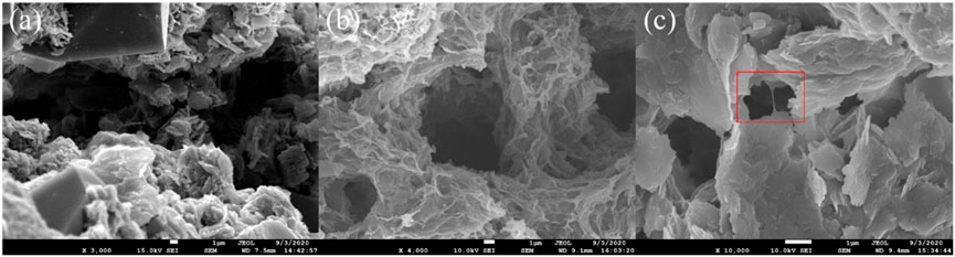
FIGURE 11. Scanning electron microscopy (SEM) images of core surfaces: (A) before fracturing fluid injection, (B) and (C) after fracturing fluid injection.
From Figure 11A we can see the core is very clean before contacting with the fracturing fluid, and there is very little impurity except for various minerals. However, after contacting fracturing fluid, some network structures of fracturing fluid adsorption are formed on the surface of core pores (see Figure 11B). Meanwhile, some fracturing fluid is stranded in the small channels (see the red box in Figure 11C). According to SEM images, the adsorption and retention of fracturing fluid in the pore leads to the narrowing of the fluid flow channel and increases the flow resistance, which is manifested as the decrease of permeability at the macro level. However, it should be noted that these adsorption and retention do not significantly reduce the pore radius or even block the pore, so the damage to the core is much lower than that of conventional macromolecular fracturing fluids.
Cryo-transmission electron microscopy (cryo-TEM) technology is employed to explore the mechanism of viscoelasticity of fracturing fluid system. The samples were placed in a low-temperature sample box (Gatan 626), detected by JEOLJEM-1400 Gatan multi-scan CCD, and processed by digital photomicrography. The microstructure of fracturing fluid is shown in the Figure 12. Many of the worm-like substances can be easily observed in the figure. On the microscopic level, these worm-like micelles entangle with each other to form a spatial structure, so that the system exhibits macroscopic viscoelasticity.
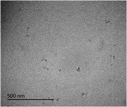
FIGURE 12. Cryo-TEM image of the fracturing fluid system.
In this study, a CO2 sensitive VES fracturing fluid was first developed. Then the viscoelasticity, temperature resistance, shear resistance and recycling performance of the fracturing fluid were evaluated by rheometer. Furthermore, other key application properties of fracturing fluids including leak-off performance, gel breaking performance and core damage performance were tested. Finally, the microscopic morphology of fracturing fluid was observed by transmission electron microscope. The specific conclusions are as follows:
(1) The new CO2 sensitive fracturing fluid is composed of 60 mmol/L FMES, 60 mmol/L triethylenetetramine, 540 mmol/L NaCl and water.
(2) After contacting with CO2, the three-dimensional structure formed by worm-like micelles in the solution significantly increases the viscosity and viscoelasticity of the fracturing fluid.
(3) The fracturing fluid has strong temperature resistance and shear resistance. The viscosity of fracturing fluid is higher than 20 mPa·s at 80°C.
(4) After the fracturing fluid is cyclically exposed to CO2 and other gas, the viscosity presents a repeatable rise and fall, which indicates that the fracturing fluid can be recycled after being recovered on the ground.
(5) After being injected into the formation, fracturing fluids can leak-off into the matrix and cause certain damage to the reservoir, while the damage rate is less than 35%.
The original contributions presented in the study are included in the article/Supplementary Material, further inquiries can be directed to the corresponding authors.
BW took the temperature and shear resistance research of the fracturing fluid. XS constructed the fracturing fluid system and took the rheology and microstructure test of the fracturing fluid. CD took the recycling performance and leak-off tests of the fracturing fluid. SH took the breaking ability and core permeability regaining tests. HD tested the viscoelastic performance of fracturing fluid system.
The work was supported by the National Key Research and Development Project (2019YFA0708700), the National Natural Science Fund of China (51834010, 51874337) and the Key Research Project of Sinopec Petroleum Engineering Company (SG20-16K).
BW, XS, SH, and HD were employed by Sinopec Matrix Co., LTD.
The remaining author declares that the research was conducted in the absence of any commercial or financial relationships that could be construed as a potential conflict of interest.
All claims expressed in this article are solely those of the authors and do not necessarily represent those of their affiliated organizations, or those of the publisher, the editors and the reviewers. Any product that may be evaluated in this article, or claim that may be made by its manufacturer, is not guaranteed or endorsed by the publisher.
Acharya, D. P., and Kunieda, H. (2006). Wormlike micelles in mixed surfactant solutions. Adv. Colloid Interface Sci. 123, 401–413. doi:10.1016/j.cis.2006.05.024
Almuntasheri, G. A. (2014a). A critical review of hydraulic-fracturing fluids for moderate- to ultralow-permeability formations over the last decade. Spe Prod. Operations 29 (04), 243–260. doi:10.2118/169552-pa
Almuntasheri, G. A. (2014b). A critical review of hydraulic-fracturing fluids for moderate- to ultralow-permeability formations over the last decade. Spe Prod. Operations 29 (4), 243–260. doi:10.2118/169552-pa
Barati, R., and Liang, J. (2014). A review of fracturing fluid systems used for hydraulic fracturing of oil and gas wells. J. Appl. Polym. Sci. 131 (16). doi:10.1002/app.40735
Clark, J. B. (1949). A hydraulic process for increasing the productivity of wells. J. Petroleum Technol. 1 (01), 1–8. doi:10.2118/949001-g
C.N.D.R.C (2008). “General technical specifications of fracturing fluids,” in General technical index of viscoelastic surfactant fracturing fluid, 4.
C.N.E.A. (2016). The evaluation measurement for properties of water-based fracturing fluid, Performance evaluation methods of fracturing fluid. Beijing: China National Energy Administration, 19–21.
Dai, C., Zhang, Y., Gao, M., Li, Y., Lv, W., Wang, X., et al. (2017). The study of a novel nanoparticle-enhanced wormlike micellar system. Nanoscale Res. Lett. 12 (1), 431. doi:10.1186/s11671-017-2198-2
Dan, L., Li, J., Zou, C., Cui, H., Ni, Y., Liu, J., et al. (2020). Recycling flowback water for hydraulic fracturing in Sichuan Basin, China: Implications for gas production, water footprint, and water quality of regenerated flowback water. FUEL 272 (117621), 117621. doi:10.1016/j.fuel.2020.117621
Dreiss, C. A. (2007). Wormlike micelles: Where do we stand? Recent developments, linear rheology and scattering techniques. Soft Matter 3 (8), 956–970. doi:10.1039/b705775j
Du, W., Wan, Y., Zhong, N., Fei, J., Zhang, Z., Chen, L., et al. (2011). Status quo of soil petroleum contamination and evolution of bioremediation. Pet. Sci. 8 (4), 502–514. doi:10.1007/s12182-011-0168-3
Fan, K., Sun, R., Elsworth, D., Dong, M., Li, Y., Yin, C., et al. (2020). Radial permeability measurements for shale using variable pressure gradients. Acta Geol. sinica‐. Engl. Ed. 94 (2), 269–279. doi:10.1111/1755-6724.14304
Granek, R., and Cates, M. (1992). Stress relaxation in living polymers: Results from a Poisson renewal model. J. Chem. Phys. 96 (6), 4758–4767. doi:10.1063/1.462787
Harris, P. C., Morgan, R. G., and Heath, S. J. (2005). “Measurement of proppant transport of frac fluids., in SPE annual technical conference and exhibition (Dallas, TX: Society of Petroleum Engineers)
Jessop, P. G., Mercer, S. M., and Heldebrant, D. J. (2012). CO2-triggered switchable solvents, surfactants, and other materials. Energy Environ. Sci. 5 (6), 7240–7253. doi:10.1039/c2ee02912j
Jr, R. A. W., Asadi, M., Leonard, R. S., and Rainbolt, M. (2003). “Monitoring fracturing fluid flowback and optimizing fracturing fluid cleanup in the bossier sand Using chemical frac tracers,” in Spe European formation damage conference.
Li, F. B., Yang, J. J., Li, Q., and Wu, H. (2014). Review of treatment methods for fracturing flowback fluid. Adv. Mat. Res. 881-883, 659–662. doi:10.4028/www.scientific.net/amr.881-883.659
Liu, H., Zhang, J., and Zhang, S. (2009). Property and design of clean acid fracturing fluid with multi-function. Acta Pet. Sin. 30 (3), 427–429.
Lv, Q., Li, Z., Li, B., Li, S., and Sun, Q. (2015). Study of nanoparticle–surfactant-stabilized foam as a fracturing fluid. Ind. Eng. Chem. Res. 54 (38), 9468–9477. doi:10.1021/acs.iecr.5b02197
Montgomery, C. T., and Smith, M. B. (2010). Hydraulic fracturing: History of an enduring technology. J. Petroleum Technol. 62 (12), 26–40. doi:10.2118/1210-0026-jpt
Mu, J., Li, G., Jia, X., Wang, H., and Zhang, G. (2002). Rheological properties and microstructures of anionic micellar solutions in the presence of different inorganic salts. J. Phys. Chem. B 106 (44), 11685–11693. doi:10.1021/jp014096a
Mu, J., and Li, G. (2001). The formation of wormlike micelles in anionic surfactant aqueous solutions in the presence of bivalent counterion. Chem. Phys. Lett. 345 (1), 100–104. doi:10.1016/s0009-2614(01)00799-0
Rehage, H., and Hoffmann, H. (1988). Rheological properties of viscoelastic surfactant systems. J. Phys. Chem. 92 (16), 4712–4719. doi:10.1021/j100327a031
Shariatpanahi, S. F., Strand, S., and Austad, T. (2010). Evaluation of water-based enhanced oil recovery (EOR) by wettability alteration in a low-permeable fractured limestone oil reservoir. Energy fuels. 24, 5997–6008. doi:10.1021/ef100837v
Sullivan, P. F. (2006). “Optimization of a visco-elastic surfactant (VES) fracturing fluid for application in high-permeability formations,” in SPE international symposium and exhibition on formation damage control (Lafayette, LA: Society of Petroleum Engineers).
Sun, X., Gao, Z., Zhao, M., Gao, M., Du, M., and Dai, C. (2019). Development and evaluation of a novel seawater-based viscoelastic fracturing fluid system. J. Petroleum Sci. Eng. 183, 106408. doi:10.1016/j.petrol.2019.106408
Wang, J., Wang, S., Lin, W., Kang, Z., and You, Q. (2017). Formula optimization and rheology study of clean fracturing fluid. J. Mol. Liq. 241, 563–569. doi:10.1016/j.molliq.2017.06.050
Wu, X., Huang, Y., Fang, S., Dai, C., Li, H., Xu, Z., et al. (2018a). CO2-responsive smart wormlike micelles based on monomer and “pseudo” gemini surfactant. J. industrial Eng. Chem. 60, 348–354. doi:10.1016/j.jiec.2017.11.021
Wu, X., Zhang, Y., Sun, X., Huang, Y., Dai, C., and Zhao, M. (2018b). A novel CO2 and pressure responsive viscoelastic surfactant fluid for fracturing. Fuel 229 (OCT.1), 79–87. doi:10.1016/j.fuel.2018.04.081
Yin, H.-Y., Zhang, R.-S., Cui, J., Wu, J.-W., and Feng, Y.-J. (2019). A salt-induced viscosifying smart polymer for fracturing inter-salt shale oil reservoirs. Pet. Sci. 16 (4), 816–829. doi:10.1007/s12182-019-0329-3
Zhang, S.-C., Lei, X., Zhou, Y.-S., and Xu, G.-Q. (2015a). Numerical simulation of hydraulic fracture propagation in tight oil reservoirs by volumetric fracturing. Pet. Sci. 12 (4), 674–682. doi:10.1007/s12182-015-0055-4
Zhang, Y., An, P., Liu, X., Fang, Y., and Hu, X. (2015b). Smart use of tertiary amine to design CO2-triggered viscoelastic fluids. Colloid Polym. Sci. 293 (2), 357–367. doi:10.1007/s00396-014-3421-7
Zhang, Y., Chu, Z., Dreiss, C. A., Wang, Y., Fei, C., and Feng, Y. (2013a). Smart wormlike micelles switched by CO2 and air. Soft Matter 9 (27), 6217–6221. doi:10.1039/c3sm50913c
Zhang, Y., and Feng, Y. (2015). CO2-induced smart viscoelastic fluids based on mixtures of sodium erucate and triethylamine. J. Colloid Interface Sci. 447, 173–181. doi:10.1016/j.jcis.2014.11.003
Zhang, Y., Feng, Y., Wang, J., He, S., Guo, Z., Chu, Z., et al. (2013b). CO2-switchable wormlike micelles. Chem. Commun. 49 (43), 4902. doi:10.1039/c3cc41059e
Zhao, M., Gao, Z., Dai, C., Sun, X., Zhang, Y., Yang, X., et al. (2019). Effect of silica nanoparticles on wormlike micelles with different entanglement degrees. J. Surfactants Deterg. 22 (3), 587–595. doi:10.1002/jsde.12252
Keywords: CO2 sensitive fluid, hydraulic fracturing, viscoelastic, performance evaluation, microstructure
Citation: Wu B, Sun X, Dai C, Hou S and Du H (2022) A novel CO2 sensitive and recyclable viscoelastic fluid system for fracturing. Front. Earth Sci. 10:990963. doi: 10.3389/feart.2022.990963
Received: 11 July 2022; Accepted: 02 August 2022;
Published: 25 August 2022.
Edited by:
Wenhui Song, China University of Petroleum, Huadong, ChinaReviewed by:
Mingyong Du, University of Western Australia, AustraliaCopyright © 2022 Wu, Sun, Dai, Hou and Du. This is an open-access article distributed under the terms of the Creative Commons Attribution License (CC BY). The use, distribution or reproduction in other forums is permitted, provided the original author(s) and the copyright owner(s) are credited and that the original publication in this journal is cited, in accordance with accepted academic practice. No use, distribution or reproduction is permitted which does not comply with these terms.
*Correspondence: Xin Sun, dXBjc3VueGluQDE2My5jb20=; Caili Dai, ZGFpY2xAdXBjLmVkdS5jbg==
Disclaimer: All claims expressed in this article are solely those of the authors and do not necessarily represent those of their affiliated organizations, or those of the publisher, the editors and the reviewers. Any product that may be evaluated in this article or claim that may be made by its manufacturer is not guaranteed or endorsed by the publisher.
Research integrity at Frontiers
Learn more about the work of our research integrity team to safeguard the quality of each article we publish.