 Shaowei Wei1
 Peiyong Wei
- 1Railway Engineering Research Institute, China Academy of Railway Sciences Group Co. Ltd, Beijing, China
- 2Yunnan Infrastructure Investment Co. Ltd, Kunming, China
- 3Beijing Tieke Special Engineering Technological Development Co. Ltd, Beijing, China
- 4Southwest Transportation Construction Group Co. Ltd, Kunming, China
Steel-tube grouting technology has been widely applied in the slope control engineering. While the anti-sliding performances of different connection modes of grouted steel tubes still needs further investigation. In this paper, a large-scale model test was used to study the influence of three types of pile connections, namely a whole pile without connection, with a reinforcement welded connection, and with a casing connection, on the anti-sliding performance of multi-stage grouted steel-tube pile. The results showed that the slope could be reinforced by all multi-stage grouted steel-tube pile structures controlled by different pile connection modes, and the composite anti-sliding body of the “root-shape” cement column could be formed around the pile, which effectively improved the perimeter of the pile and enhanced the anti-sliding performance of steel-tube pile structure. The steel-tube piles with different pile connection modes all suffered from bending failure near the sliding surface. The horizontal anti-sliding force of the welded steel tube 6 m in length was 1.4 t per root, which was higher than that of the whole pile. The horizontal anti-sliding force of steel casing connected steel-tube with 6 m in length was 8.8 t per root, which was higher than that of the whole pile. The casing connected steel tube had stronger anti-sliding ability due to the increased diameter of the steel tube near the sliding surface. Therefore, it is recommended that the casing connection mode be used in the connection design of steel pipes, and the reinforcement of a pile body near the sliding surface should be strengthened to improve the flexural failure capacity.
Introduction
In recent years, steel-tube grouting technology has been widely applied in the slope control engineering which requires a small slope space and can be implemented quickly. This technology can combine a grouting body and a pile body to form a cement anti-sliding body similar to a “tree root pile” which effectively improves the anti-sliding performance (Zhang et al., 2019; Zhou et al., 2019). The anti-sliding mechanism and stress characteristics of the grouted steel tube through indoor model tests (Yan et al., 2009; Chen et al., 2011) and large-scale test models (Wei et al., 2019), and the circular pile has the cross-sectional shape advantages because of its uniform force transmission. In practical engineering application, the steel-tube grouting technology has been proved to be effective to prevent and solve the engineering problems (Zhu et al., 2006; Wang et al., 2016; Zhang et al., 2019). Among the different techniques usually employed to stabilize landslide bodies, the use of one or more rows of piles firmly embedded in the stable portion of the slope is commonly considered a reliable and effective measure (Zhu et al., 2004; Troncone et al., 2021). The influence of the pile parameters on the probabilistic analysis results of the reinforced slope was studied (Gong et al., 2004; Gong et al., 2019). The factors influencing the response of piles and pile-groups include the axis-to-axis pile spacing, the thickness of stable soil mass, the depth of pile embedment, the pile diameter, and the pile group configuration (Xiang and Song, 2008; Kourkoulis et al., 2011; Sun et al., 2014; Zhao et al., 2014; Li et al., 2015; Liu et al., 2015; Tan, 2016). Various results for previous studies have been obtained on the mechanical properties, cross-sectional forms, and application effects of steel tubes. The commonly used specification of steel flower tubes is 6 m in length, and the depth of embedded steel tubes is usually 10–20 m. Therefore, it is necessary to connect steel tubes to piles to satisfy the requirements of the design and construction. The stability and effect of the whole pile after the pile extension need to be considered.
Many examples have shown that the effect of the pile extension greatly affects the construction quality and the role of the pile body. As a result, it is highly important to study the types and methods of pile extensions. Shi and Yang, (2011) introduced a prestressed pipe pile connection and proposed the control points of the connections. Fan et al. (2013) discussed the connection of anti-pulling square piles through theoretical analysis and experimental study by testing the tensile performance under the new connection mode and found that the upset head and end plate were the weak links of the square pile. Li et al. (2009) conducted an axial tensile bearing capacity test on welded high-strength prestressed pipe piles, which showed the concrete of the pile shaft cracked first. Liu et al. (2008) carried out bending capacity tests on the welded joint of a prestressed concrete pipe pile to show that the joint of the pipe pile exhibited brittle failure and that strengthening measures were needed at the joint. He and Li (2008) used a Ø102 mm × 5 mm seamless steel tube to case the steel-tube connection pile, and a Ø89-mm steel pipe was inserted into the Ø102-mm steel pipe and welded along the joint around the steel pipe. The length of the joint steel pipe was 120 mm for the slope control engineering of the east-west trunk road of Buji, Shenzhen. Li et al. (2015) employed connectors (threaded connectors) to connect the steel pipe pile in an existing building reinforcement project, and the connectors were shown to meet the tensile and bending strength requirements through testing. In general, most of the above research results were related to the steel pipe connection construction process in practical engineering. While the influence of different connection modes of grouted steel tubes still need further investigation.
In this paper, the anti-sliding performances of different connection modes of grouted steel tubes were studied, an in-situ large-scale model test with the slot 6.0 m in height, 1.5 m in width and 6.5 m in length was carried out to better reflect the actual stress characteristics of different pile connection modes of grouted steel tubes.
Connection modes of grouted steel tube
Two types of connections are generally adopted for steel tubes, including the reinforcement welding and threaded casing connections. According to the requirements of the Steel-Tube Pile Welding Process in Technical Code for Foundation Reinforcement of Existing Buildings (JGJ 123, 2012), floating rust, oil contamination, and other impurities on the connecting parts must be cleaned before the steel tube is connected to the pile. The grouted steel tube was a Ø89mm × 5 mm seamless steel pipe, shown in Figure 1A. The butt welding was adopted at the joints between the steel tubes. Three connecting steel bars shown in Figure 1A, 20 mm in diameter were welded equidistantly at the joint, so that the steel tube could be positioned in the drilling hole. The verticality was strictly controlled during the welding of the upper and lower sections of the pile. The gap between the butt joints was maintained according to the design requirements, being 2–4 mm. The welding wire (automatic welding) or welding rod was dried. The welding was conducted in a symmetric and multi-layer pattern, and the joints of each layer of the steel-pipe pile weld were staggered. Meanwhile, the welding slags were removed.
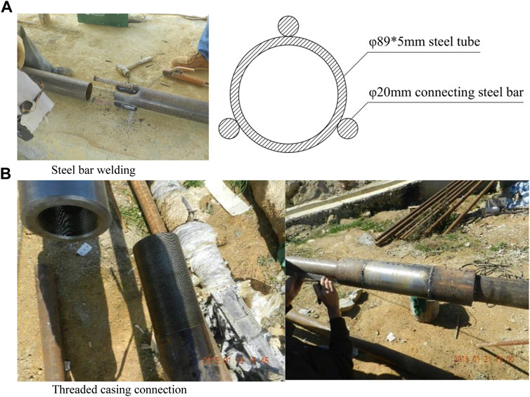
FIGURE 1. Steel bar welding and threaded casing connection. (A) Steel bar welding. (B) Threaded casing connection.
A threaded casing connection was used to connect two steel pipes with the threaded casing, and its joint was welded with a welding rod. The grouted steel tube was a seamless steel tube with dimensions of Ø89mm × 5 mm, and butt welding was applied at the joints between the steel pipes. An overlapping seamless steel pipe with dimensions of Ø120mm× 15 mm was used for the outer part of the tube, and the over-lapping length was no less than 100 mm at each end, shown in Figure 1B.
Field model test
Test description
To better simulate the stress characteristics and failure modes of a steel pipe with different connection modes in the practical engineering, a model test was carried out in a 1:1 prototype test tank with 6.0 m in height, 1.5 min width and 6.5 m in length, as shown in Figure 2A. Mention that dimensions in Figure 2 are in cm.
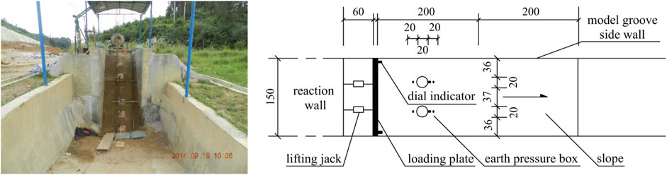
FIGURE 2. Test site and plane distribution of measuring points.
The model groove was mainly composed of the reaction wall with 5.0 m in height, 2.1 m in width and 3.0 m in length, the groove side wall and the loading plate with 3.0 m in height, 1.45 m in width and 0.08 m in length, as displayed in Figure 2B. To ensure the reaction wall remained in a static state during the test, the rubble concrete with 6.5 m in height, 3.0 m in width and 3.0 m in length was filled at the back of the reaction wall away from the side of the loading plate for the reinforcement. The bottom of the loading plate was located on the sliding surface platform in the groove, and the top of the steel plate was fixed by a roller installed on the side wall of the model groove, shown in Figure 3. The displacement of the steel plate was produced by a small horizontal thrust depending on the action of the pulley. The controlled bending deformation of the steel plate was within 3 mm under the horizontal thrust of the jack during the test.
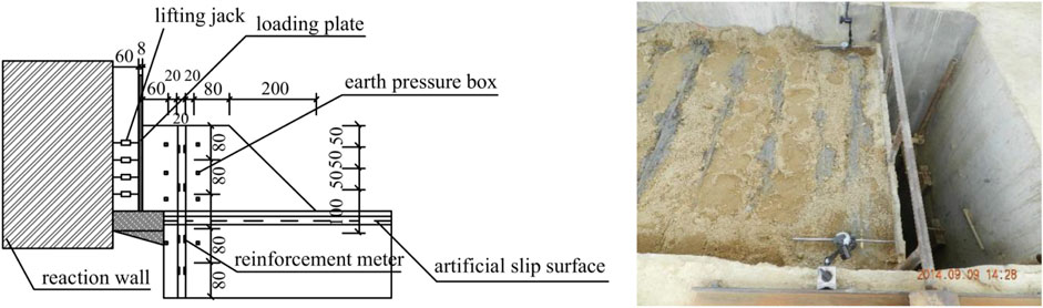
FIGURE 3. Schematic diagram of pile strain gauge location and tinplate protection box.
Test scheme
Four groups of tests were conducted to better study the influence of different connection methods of the steel tube on the bending performance, including the no pile test, the single pile test, the single pile welding connection test and the single pile casing connection test. The specific scheme of each group is shown in Table 1.
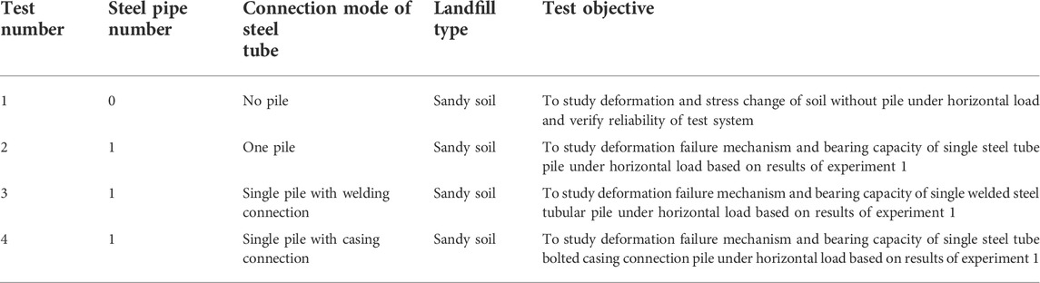
TABLE 1. Test plan.
Test procedure
The single pile welding connection test which is the third group, is taken as an example. The test procedure is described as follows.
1) Soil sample preparation
The clay and sand were mixed in the proportion of 1:5 to make the slope material, and the water content was controlled at 10–15%. It was determined that ρ = 1.8 g/cm3, C = 5 kPa, and φ = 34° through the indoor direct shear tests. A soil slip zone with a thickness of 15–20 cm was constructed through the saturated soft clay, with C being 15 kPa and φ being 21° during the experiment.
2) Soil sample filling
The soil materials were compacted and filled in layers, and each layer of filling could not exceed 20 cm. The slope rate that is the ratio of the height in the vertical direction of the slope to the projection length in the horizontal direction of the slope is 1:1, and the Earth pressure box (JMZX-5006AT) with a measuring range of 2 MPa was embedded in the corresponding position of the slope body.
3) Steel tube preparation
Two steel pipes 3 m in length with dimensions of Ø89 mm × 5.0 mm were selected for the test piles, on which grouted holes 8 mm in diameter were drilled with a spacing of about 10 cm for the multi-stage grouting control. The strain gauges were welded outside the steel pipe to effectively record the soil stress. The strain gauges were protected from the influence of water and mud outside the pipe with a tinplate protection box, which was sealed with 302 glue. The verticality was strictly maintained during the welding of the upper and lower sections of the steel tube. The gap between the butt joints was maintained based on the design requirements. Three steel bars 20 mm in length were symmetrically welded around the joint. The operation diagram is shown in Figure 3. Mention that dimensions in Figure 3 are in cm.
4) Steel tube installation
A straight hole with 150 mm in diameter was drilled by a down-hole drill after filling the model trench. A plumb line was used to adjust the verticality of the drill pipe to ensure that the drilling hole was vertical during drilling and to lower the pipe after drilling. In order to ensure there was no horizontal displacement at the bottom of the steel tube during the test, the concrete pier was set at the bottom of the model groove in advance, and the steel tube was directly inserted into the concrete pier, which was drilled through. The grouting was controlled in multiple stages after the steel tube installation completion.
5) Multi-stage grouting
The grouting equipment for the tests mainly included the grouting machine, the mixing box, and the slurry box. The cement and water in the fixed proportion were first poured into the mixing box for mixing, with a size of 1.2 m × 1.0 m × 0.3 m, and the uniformly mixed slurry was poured into the slurry box. The grouting pipe was used to connect the grouting box and grouting machine. The grouting machine was opened, and the slurry was injected into the borehole which was the primary grouting outside the pipe or the steel pipe which was the secondary splitting grouting through the grouting gun head driven by the pressure. The grouting outside the tube was performed quickly after the installation of the steel tube until the orifice overflowed. The opening of the steel tube was sealed with a steel cover during the second grouting because of the large grouting pressure. The multiple split grouting was employed after 5–12 h of grouting outside the tube when the axial compressive strength of the grouting body was no less than 3 MPa. The secondary grouting pressure was measured by the pressure gauges connected to the pipe. The secondary grouting was stopped immediately when the grouting pressure exceeded the allowable pressure (8 MPa) of the grouting machine or when slurry leak-age occurred on the slope.
6) Force load
The simulation of the landslide thrust in this test used eight hydraulic jacks that operated synchronously, and the load force of the jacks equaled the magnitude of the landslide thrust. The method of displacement control loading, in which the loading plate was moved horizontally during the loading process, was adopted during the test to make it easier to collect data and make observations. The difference between the upper and lower displacement of the loading plate was no more than 3 mm, and the loading was recorded for each horizontal displacement of the loading plate of 1–5 cm. The displacement of the loading plate was smaller in the early stage of the test, about 1–3 cm, and then it became larger in the later stage, about 4–5 cm. The loading test was terminated when the soil entered the plastic state; that is, the test was terminated when the loading thrust basically remained constant.
7) The filling was removed, and the test was complete.
Monitoring system
The horizontal thrust was measured by eight pressure gauges installed on the jack. The displacement of the loading plate was measured by two dial indicators installed on the loading plate. The soil pressure box and dial indicator were embedded in advance to measure the soil pressure and the horizontal displacement of the slope surface. The bending measurement of the steel-tube pile body was obtained through theoretical calculations based on the values of the strain gauge on both sides of the steel tube and the strain gauge in front of and behind the pile, respectively. The specific instrument layout is illustrated in Figures 2, 3.
Test results
Results of multi-stage controlled grouting
Multi-stage controlled grouting tests were carried out with different connection modes in the second, third, and fourth groups of tests. The position of the grouting hole was 2.5–4 m below the pile top, and the position of the sliding surface was about 3 m. The interval between the first and second grouting time in the whole pile test of the second group was 7.5 h. Figure 4 illustrates the variations of the grouting pressure with time. The secondary splitting pressure reached 5.8 MPa within 30 s after the splitting began, and then the pressure quickly dropped to 0–2 MPa, indicating that the primary grouting body was split successfully. The splitting time lasted 13 min, and the slurry feed exceeded 1.2 t. The test was terminated after the splitting slurry flowed from the bottom of the loading plate and the lower part of the slope surface simultaneously, as shown in Figure 5.
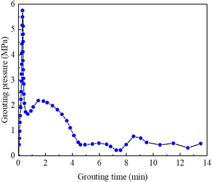
FIGURE 4. Controlled grouting pressure curve of the second group of experiments.
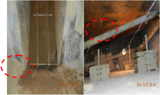
FIGURE 5. Slurry emerging from the bottom of the loading plate and the lower part of the slope at the same time in the second group of experiments.
The interval between the first and second grouting in the welded steel-tube grouting of the third test group was 7.5 h. The secondary splitting pressure reached 6 MPa within 30 s after the splitting began, and then the pressure quickly dropped to 0–2 MPa, implying that the primary grouting body was split successfully. The splitting time lasted 14 min, and the slurry feed exceeded 1.3 t. The test was terminated after the splitting slurry flowed from the lower part of the slope surface simultaneously, as shown in Figure 6.
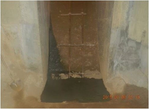
FIGURE 6. Slurry emerging from the lower part of the slope in the third group of experiments.
The interval between the first and second grouting in the threaded casing connected steelcasing connected steel-tube grouting test of the fourth group was 7.5 h. The secondary splitting pressure reached 6 MPa within 30 s after the splitting began, and then the pressure quickly dropped to 0–2 MPa, indicating that the primary grouting body was split successfully. The splitting time lasted 11 min, and the slurry feed exceeded 1.4 t. The test was terminated after the splitting slurry flowed from the bottom of the loading plate and the lower part of the slope surface simultaneously, as shown in Figure 7.
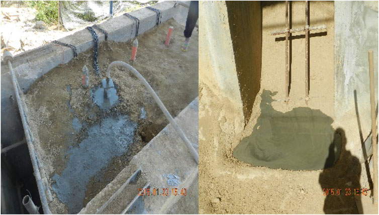
FIGURE 7. Slurry emerging from the top and bottom of the slope surface in the fourth group of experiments.
The filling in the model tank was excavated after these three groups of tests were completed. The slurry was mainly distributed in the lower part of the sliding surface through the second split grouting. The bodies were joined together, and a “root-shaped” cement column formed at the bottom of the pile, as shown in Figure 8.
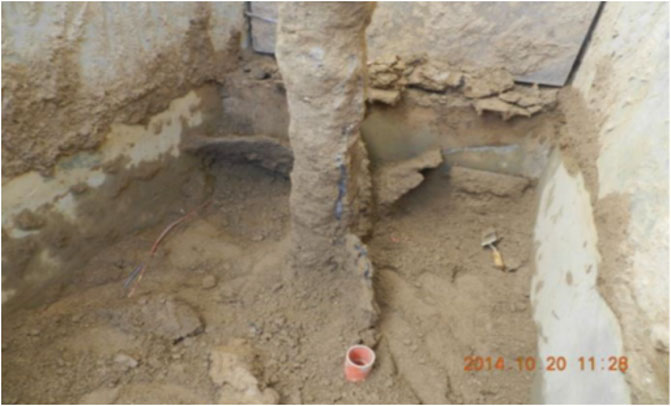
FIGURE 8. Test slurry formed a “tree root” cement column in the lower part of the pile.
Analysis of landslide thrust characteristics
Through the analysis and comparison of the loading plate displacement and horizontal thrust in the four groups of tests (as shown in Figure 9), the test soil entered the plastic state after about 20 times thrust loading in the no-pile test, the single pile test, the single pile welding connection test and the single pile casing connection test. The horizontal thrust at this time was considered to be the landslide thrust required for the plastic failure of the tested slope soil. The four groups of tests had roughly the same trend of the displacement curve under the action of horizontal thrust. After the soil body entered the plastic state, the landslide thrust was 72.9 t in the no pile test (the first group). Setting a single pile of the whole steel tube in the model (the second group) would make an increase of the landslide thrust to 83.3 t. The landslide thrust with the welded steel tube (the third group) was increased to 84.7 t. The landslide thrust with a threaded casing connected to the steel tube (the fourth group) could reach 93.5 t.
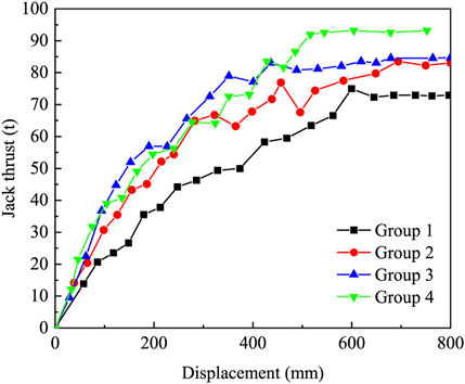
FIGURE 9. Relationship between jack thrust and displacement of the first group experiments.
Multiple lateral cracks were formed on the slope surface with the increase of the load in each group of tests. In groups one to three, the cracks gradually formed at the top of the slope, while the damage occurred at the slope foot during the group four test. Figure 10 shows the schematic diagram of the slope failure in the first group (left) and the third group (right) of tests.
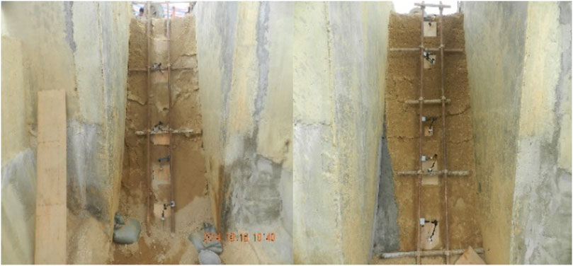
FIGURE 10. Slope failure diagram of the first group experiments (left) and the third group experiments (right).
Based on the horizontal landslide thrust tests described above, the steel tube set in the model soil body could effectively improve the mechanical performance of the slope soil, while the steel tube with different connection methods could provide different values of the anti-slip force. In group one, the horizontal anti-slip force increased by about 14.27% due to the presence of the entire pile of steel tubes, the welded connection steel tube increased the horizontal anti-sliding force by about 16.19%, and the threaded casing connected steel tube increased it by about 28.26%.
The increased horizontal anti-sliding force of the threaded casing connected steel tube was greater than that of the other two groups, resulting from a greater landslide thrust at the position near the sliding surface. The widened casing diameter here partially enhanced the anti-sliding performance of the steel tube. Therefore, the steel tube with the threaded casing connection had the best mechanical performance because of its casing at the connection, followed by the welded connection. The whole pile of steel flower tubes was not as good as the other two tubes.
Bending moment analysis of steel tube
(1) Calculation of bending moment of pile body from steel bar stress value
A reinforcement meter was set on both sides of the pile body for this test. During the test, the stress change of the pile body under stress was measured. The bending moment of the pile body was inversely deduced through the measured stress change of the pile body and the formula for the bending bearing capacity of a circular concrete section in Appendix e.0.4 of Specification for Concrete Structure Design (GB 50010, 2010). The formula is as follows:
where ft is design value of the shear strength of the slurry, being 1.71 MPa; fv is the design value of the shear strength of the Ø89 mm steel tube and the casing, being 180 MPa; design value of the shear strength of the casing; Ec is the elastic modulus of the slurry with a value of 2.5 × 10⁴ MPa; Es represents the elastic modulus of the steel tube, with a value of 2.06 × 10⁵ MPa; d is the diameter of the pile, being 130 mm; d1 is the outer diameter of the steel tube, being 89 mm; d2 is the inner diameter of steel tube, being 79 mm; fcm is the design value of the bending compressive strength of the slurry, being 19.1 MPa; fy is the de-sign value for the tensile strength of the steel pipe, being 310 MPa; r is the radius of the circular cross section, being 65 mm; rs is a circular radius located in the barycenter of the steel pipe section; α is the ratio of the central angle (RAD) of the cross section in the compression zone to 2π; αt is the ratio of the cross-sectional area of the tensile steel pipe to the total steel pipe area, where αt =1.25∼2α. This method can be used to analyze the bearing characteristics of the pile body.
In this model test, the steel tube had dimensions of Ø89 mm × 5 mm. The drilling diameters of the second and third group were 130 mm, and the drilling diameter of the fourth group was 170 mm. The grouting material was a pure cement slurry prepared with ordinary Portland cement (P.O. 42.5), whose strength grade was 42.5 MPa.
Through Eq. 1, it was determined that the values of α and αt were 0.3657 and 0.5186, respectively. These values were substituted into Eqs 2, 3, and the bending capacity of the steel tube Mu=24.30 kNm and the shear capacity Q=260.07 kN were obtained.
2) Analysis of bending moment
The steel tube was used in the second, third, and fourth groups of tests. The bending moment of the steel-tube pile could be acquired by the inversion of the above calculation method, and the diagrams of the variations of the bending moment of the steel-tube pile during the test loading are shown in Figures 11–13.
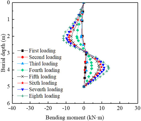
FIGURE 11. Moment diagram of steel flower tube of the second group experiments.
The bending moment distributions in the three groups of tests were similar, basically forming S shapes. The upper and lower parts of the sliding surface close to the loading plate side were compressed and tensioned, respectively. The maximum bending moment above the sliding surface was 2.0–2.5 m from the top. The maximum bending moment below the sliding surface was about 4.0 m from the top. The strain gauge was damaged after the eighth loading process (loading displacement: 144.2 mm; displacement at the top of the steel tube: 115.3 mm) in the second group of tests. At this time, the maximum bending moment of the steel-tube pile occurred at a position 4 m from the top, and its value was about 13.3 kN·m when the strain gauge failed. The whole pile steel tube exhibited 54.73% of the bearing capacity of the steel tube, shown in Figure 11.
The strain gauge was damaged after the sixth loading (loading displacement: 185.7 mm; displacement at the top of the steel tube: 141.9 mm) in the third group of tests. At this time, the maximum bending moment of the steel-tube pile occurred at the position 4 m from the top, and its value was about 18.14 kN·m. When the strain gauge failed, the whole pile steel tube exhibited 74.65% of the bearing capacity of the steel tube, shown in Figure 12.
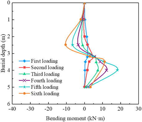
FIGURE 12. Moment diagram of steel flower tube of the third group experiments.
The strain gauge was damaged after the sixth loading (loading displacement: 197.9 mm; displacement at the top of the steel tube: 168.5 mm) in the fourth group of tests. At this point, the maximum bending moment of the steel-tube pile occurred at a position 4 m from the top, and its value was about 26.01 kN·m. The maximum bending moment exceeded the limit value of 24.3 kN·m of the bending capacity of the steel tube. The steel tube did not break, as the local bending capacity of the casing connection was strengthened, but the tube was damaged by the bending, and its exertion ratio of the bearing capacity was 100%. The bending moment diagram is shown in Figure 13.
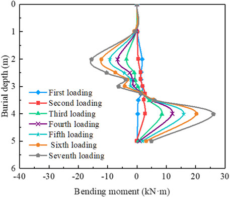
FIGURE 13. Moment diagram of steel flower tube of the fourth group experiments.
In general, the second, third, and fourth groups of tests had similar bending moment distributions, which were 1–3 m from the top near the side of the loading plate. The compression was applied at the upper part of the sliding surface, and the tension was applied at the lower part of the sliding surface close to the side of the loading plate. The maximum values of the bending moment for the upper and lower parts of the sliding surface of the whole pile (group 2) were similar, while the maximum bending moments of the upper parts of the sliding surfaces of the welding connection and the casing connected steel tubes were significantly smaller than those of the lower parts of the sliding surfaces. The maximum bending moments in these three groups of tests occurred about 4 m below the top.
The moment values of the steel-tube piles with different connection modes were all generated under the landslide thrust. The moment values of the casing connected steel tube were larger than those of the welding connection steel tube, which were larger than those of the whole pile. This indicated that the welding and casing connection could improve the bending performance of the steel tube to varying degrees. The casing connection partly strengthened the steel tube near the sliding surface, allowing it to play a better resistance role.
Analysis of steel tube failure mode
To observe and study the stress condition and failure mode of the steel tube, the slope body was excavated after completing the tests in the second, third, and fourth groups of tests. All three sets of steel tubes were bent under the landslide thrust, and bending failure occurred at the position of the sliding surface.
In the second, third, and fourth group, all the steel tubes suffered bending failure. While the steel tube in the fourth group was subjected to a larger bending moment, and the maximum negative bending moment exceeded the ultimate bending moment of steel tube. This can mainly due to the diameter of the steel tube increased by the casing connection. As shown in Figure 14, although the steel tube in the fourth group withstood a larger bending moment, the bending degree at the time of failure was much lower than that of the third group (welding connection). Therefore, the steel tube connected by the casing had better bending resistance.
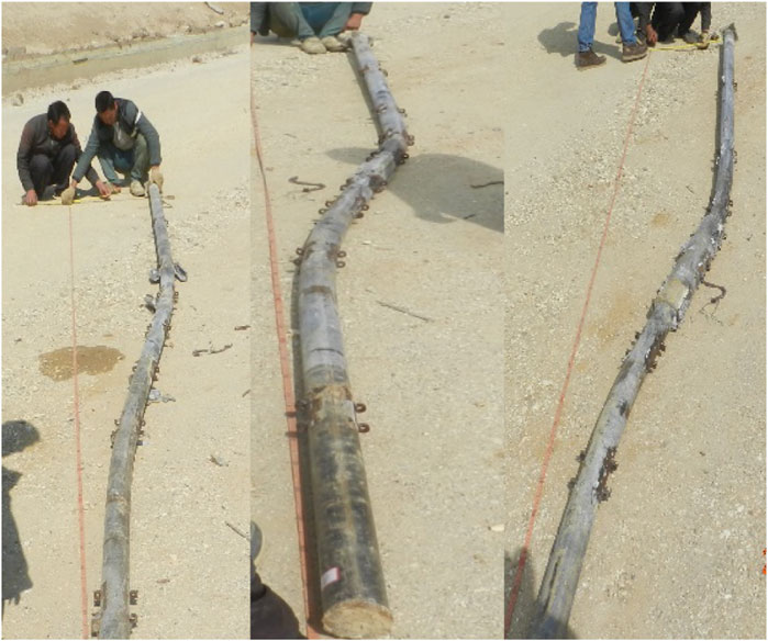
FIGURE 14. Steel flower tube failure of the second, third, and fourth group experiments.
Conclusion
Based on the multi-stage controlled grouting tests of large-scale prototypes with no pile, whole pile, welding connections, and casing connections, the effect of multiple subsections of controlled grouting steel-tube structures with different connection modes on the landslide and mechanical characteristics of steel tube were analyzed in this paper, yielding the following main conclusions.
1) The model test study showed that the whole pile and the steel-tube pile with different connection modes were effectively combined with the soil around the pile to form a “root-type” anti-sliding cement column using the multi-stage controlled grouting technology. This effectively improved the anti-sliding performance of the steel tube.
2) In the test of the multi-stage controlled grouting of the whole pile, the whole pile provided 10.4 t per tube of the horizontal anti-sliding force. The multi-stage controlled grouting steel-tube structure of the welding connection exhibited 11.8 t per piece of the horizontal anti-sliding force under the action of a landslide thrust. The multi-stage controlled grouting steel-tube structure of the casing connection provided 20.6 t per tube of the horizontal anti-sliding force. The horizontal anti-sliding force of the steel flower tube for the casing connection was 8.8 t per tube, which was higher than that of the steel flower tube for the welding connection. The horizontal anti-sliding force of the steel flower tube for the welding connection was 1.4 t per piece, which was higher than that of the whole pile and played a better role in the anti-sliding performance.
3) Compared to the multiple grouting tests of the welding connection pile, the casing connection pile produced a larger bending moment than that of the welding connection pile under the landslide thrust. The limiting bending moment of the casing connection tube exceeded the bending bearing capacity of the steel flower tube, illustrating that the casing connection pile structure could exert resistance more effectively.
4) The steel tubes in each test were damaged near the sliding surface through the model test. Both the welded and casing connections showed the characteristics of bending failure. The use of the casing connection at the joint could increase the diameter of the steel tube. Therefore, the steel tube bore a larger bending moment. It is recommended to use a casing connection in the design of a steel-tube connection and to strengthen the pile reinforcement design near the sliding surface to improve the resistance to bending failure, thereby achieving a better anti-sliding effect.
Data availability statement
The original contributions presented in the study are included in the article/supplementary material, further inquiries can be directed to the corresponding author.
Author contributions
SW: investigation and writing—original draft. XZ: preparation of field test plan. CQ, SQ: field tests. PW: supervision and writing—review and editing. QC: checking the draft. CY: test data sorting.
Funding
This study was supported by the Science and technology planning project of Department of transportation of Yunnan Provincial [2020] No. 116.
Conflict of interest
Author PW is employed by Beijing Tieke Special Engineering Technological Development Co. Ltd. Author XZ, QC, CY, and CQ are employed by Yunnan Infrastructure Investment Co., Ltd. Author SQ is employed by Southwest Transportation Construction Group Co., Ltd.The remaining authors declare that the research was conducted in the absence of any commercial or financial relationships that could be construed as a potential conflict of interest
Publisher’s note
All claims expressed in this article are solely those of the authors and do not necessarily represent those of their affiliated organizations, or those of the publisher, the editors and the reviewers. Any product that may be evaluated in this article, or claim that may be made by its manufacturer, is not guaranteed or endorsed by the publisher.
References
Chen, Q., Chen, W., Liu, S. D., and Ma, Q. J. (2011). Model test on application of grouting steel-tube micro piles to landslide reinforcement. J. Southwest Jiaot. Univ. 46, 758–763.
Fan, Q. J., Huang, G. L., Mu, H. L., and Ling, D. X. (2013). Computational analysis and experimental study on a new connection between segments of square uplift piles. Chin. J. Geotech. Eng. 35, 1011–1015.
GB 50010 (2010). Specification for concrete structure design. Beijing, China: Ministry of Housing and Urban-Rural Development of the People’s Republic of China.
Gong, J., Chen, R. P., and Chen, Y. M. (2004). Prototype testing study on micro-piles under lateral loading. Chin. J. Rock Mech. Eng. 23, 3541–3546.
Gong, W., Tang, H., Wang, H., Wang, X., and Juang, C. H. (2019). Probabilistic analysis and design of stabilizing piles in slope considering stratigraphic uncertainty. Eng. Geol. 259, 105162. doi:10.1016/j.enggeo.2019.105162 |
He, Y. H., and Li, Z. G. (2008). Steel floral tube split grouting construction technology. Constr. Technol. 1, 254–256.
JGJ 123 (2012). Technical Code for foundation reinforcement of existing buildings. Beijing, China: Ministry of Housing and Urban-Rural Development of the People’s Republic of China.
Kourkoulis, R., Gelagoti, F., Anastasopoulos, I., and Gazetas, G. (2011). Slope stabilizing piles and pile-groups: Parametric study and design insights. J. Geotech. Geoenviron. Eng. 137, 663–677. doi:10.1061/(asce)gt.1943-5606.0000479 |
Li, W. X., Liu, Q. B., and Wang, Z. (2009). Experimental study on prestressed uplift pile joints. Chin. J. Geotech. Eng. 13, 198–203.
Li, Z., Teng, Y. J., Li, Q. R., Duan, Q. W., and Li, D. Z. (2015). Micro-pile techniques for improvement project of existing buildings. China Civ. Eng. J. 48, 198–201.
Liu, F. R., Jia, L., and Li, C. (2008). The test study on welding joint flexural bearing capacity of prestressed concrete hollow square pile. J. Wuhan. Univ. Technol. 30, 105–108.
Liu, H., Xiao, S. G., and Zhang, Y. F. (2015). Experimental study on the anti-sliding mechanism of micro-pile composite structure. China Railw. Sci. 36, 18–24.
Shi, S. Y., and Yang, H. (2011). Type and influence control of connected pile for pre-stressed pipe pile. Coal Eng. 9, 45–47.
Sun, S. W., Chen, C., and Ding, H. (2014). Stability analysis of earth slopes reinforced with micro-piles. Chin. J. Geotech. Eng. 36, 2306–2314.
Tan, W. Y. (2016). Tests and detection of multi-section grouting technique of steel grouting pipes. Constr. Technol. 45, 122–128.
Troncone, A., Pugliese, L., Lamanna, G., and Conte, E. (2021). Prediction of rainfall-induced landslide movements in the presence of stabilizing piles. Eng. Geol. 288, 106143. doi:10.1016/j.enggeo.2021.106143 |
Wang, H. J., Xu, H. K., and Dong, L. J. (2016). Application of grouted steel floral tube in preventing diseased of slop retaining wall in highway. J. Geo. Hazards Environ. Preserv. 27, 92–95.
Wei, S. W., Sui, Y. Y., and Yang, J. M. (2019). Model tests on anti-sliding mechanism of circular and rectangular cross section anti-sliding piles. Rock Soil Mech. 40, 951–961.
Xiang, R. Z., and Song, G. (2008). Application of steel perforated pipe and injecting grout steel bolt pipe in reinforcement on A sloping sliding located at shang Pu expressway. Soil Eng. Found. 22, 14–17.
Yan, J. K., Yin, Y. P., and Men, Y. M. (2009). Model test study on landslide reinforcement with single micro pile. J. Eng. Geol. 17, 669–674.
Zhang, Y. F., Wei, S. W., Zhou, W. J., Li, D., and Zhou, B. (2019). Model test study on anti-sliding behaviours of multiple segmented grouting steel pile group structure. Chin. J. Rock Mech. Eng. 38, 982–992.
Zhao, X. X., Zhang, C. L., and Wang, C. (2014). Application of steel-tube bored grouting anti-sliding retaining wall to treatment of zhenqing 5-K64+600 bridge slope. World sci-tech. R. D. 36, 226–230.
Zhou, W. J., Wei, S. W., and Zhang, Y. F. (2019). Model test study on anti-sliding mechanism of multiple segment grouting steel-tube. Rock Soil Mech. 40, 1–10.
Zhu, B. L., Hu, H. T., Zhang, Y. F., Chen, Q., and Zhang, S. (2006). Application of steel-tube bored grouting anti-sliding retaining wall to treatment of landslide K108 in beijing-zhuhai expressway. Chin. J. Rock Mech. Eng. 25, 399–406.
Keywords: large-scale model test, pile connection modes, casing connection, multi-stage grouting, anti-sliding performance
Citation: Wei S, Zhang X, Qin C, Wei P, Qin S, Liu L, Chen Q and Yin C (2022) Influence of vertical grouting steel-tube connection mode on anti-sliding performance. Front. Earth Sci. 10:986894. doi: 10.3389/feart.2022.986894
Received: 05 July 2022; Accepted: 30 August 2022;
Published: 16 September 2022.
Edited by:
Zhen-Dong Cui, China University of Mining and Technology, ChinaReviewed by:
Xiaoyan Liu, China University of Mining and Technology, ChinaPengpeng Ni, Sun Yat-sen University, China
Copyright © 2022 Wei, Zhang, Qin, Wei, Qin, Liu, Chen and Yin. This is an open-access article distributed under the terms of the Creative Commons Attribution License (CC BY). The use, distribution or reproduction in other forums is permitted, provided the original author(s) and the copyright owner(s) are credited and that the original publication in this journal is cited, in accordance with accepted academic practice. No use, distribution or reproduction is permitted which does not comply with these terms.
*Correspondence: Peiyong Wei, c2Rsd3dweUBvdXRsb29rLmNvbQ==