 Yusen Kang
 Zhilin Long1*
95% of researchers rate our articles as excellent or good
Learn more about the work of our research integrity team to safeguard the quality of each article we publish.
Find out more
ORIGINAL RESEARCH article
Front. Earth Sci. , 29 August 2022
Sec. Structural Geology and Tectonics
Volume 10 - 2022 | https://doi.org/10.3389/feart.2022.986344
This article is part of the Research Topic Unconventional Reservoir Geomechanics View all 16 articles
In this paper, the adaptability characteristics of the packer to three types of common clastic rock reservoirs (mudstone, shale, sandstone) are analyzed systematically. Moreover, the identification and structural design of the packer in hydraulic fracturing are systematically conducted based on the finite element calculation. Finally, the nonlinear mathematical models of the packing safety factor and the pressure under the packer and the conditions of casing, mudstone, shale and sandstone are obtained. The results show that the maximum stress of the rubber cylinder in the three formation models of mudstone, shale and sandstone is lower than the compression set strength of the rubber cylinder, indicating that the rubber cylinder will not cause stress damage. At the same time, by analyzing the common rubber materials and constitutive models of the packers, the structure of the packer rubber cylinder and a new anti-shoulder protrusion device were redesigned. The Nitrile-butadiene rubber (NBR) meets the performance requirements of the rubber tube under the allowable pressure difference and temperature difference. The designed new anti-protrusion device can ensure the structural integrity and stress uniformity of the rubber tube, thereby ensuring good sealing performance. Under the three formation conditions of mudstone, shale and sandstone, the rubber cartridge can be in a safe working state, and its sealing width is close to the contact length of the rubber cartridge. In addition, the rubber cartridge is in a good elastic deformation range. The design of the packer in this study satisfies the third strength theory and the safety requirements. The deformation and sealing performance of the rubber cylinder are relatively stable, and the size of the rubber cylinder also meets the field requirements.
The measurement of initial stress of underground rock mass has very important practical value to improve the development efficiency of tight oil and gas resources. In addition, the test of in-situ stress is also of great significance to the safe utilization of urban space, disaster reduction and prevention. Packers are the basic equipment for obtaining in-situ stress in hydraulic fracturing tests (Yohannes., 2017; Huang et al., 2020). The research object of this study is the Jurassic Ziliujing Formation in the X area of the Sichuan Basin, China. Typically, the rocks encountered by packers in the formation are mainly mudstone, shale, and sandstone. Hydraulic fracturing is one of the methods for measuring in-situ stress specified by the International Professional Committee of Rock Mechanics Testing Technology, and it is also the most effective method for measuring deep in-situ stresses. At present, the differential pressure of some newly developed bridging packers in the world is around 35 MPa, which cannot fully meet the temperature and pressure conditions required for deep hole geostress testing (Wakuda et al., 2002; Zhao et al., 2021a; Zhao et al., 2021b; Liu et al., 2022; Zhao et al., 2022; Zheng et al., 2022). Packers are important tools for downhole stress measurements. The sealing rubber material of the packer is prone to have problems such as stress relaxation and shoulder protrusion under high temperature and high pressure or tough environment, furthermore, it will lead to sealing failures (Akhtar et al., 2012). Shale is developed in the Jurassic Ziliujing Formation in the Sichuan Basin, and the shale has strong toughness or creep characteristics. It is easy to soften and expand after soaking with annotation, and it has small deformation modulus and poor sliding stability. There are a large number of interlayer pores and micro-fractures developed in shale rocks (Figure 1), thus higher requirements for deep hole in-situ stress testing are needed.
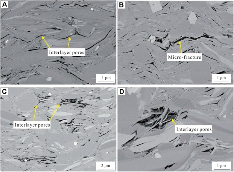
FIGURE 1. Development characteristics of interlayer pores and microfractures in the Ziliujing Formation shale in the Sichuan Basin (Liu et al., 2021). Notes: (A) Well F1, 2736.3 m; (B) Well X101, 2149.77 m; (C) WellX101, 2269.94 m; (D)Well Y30, 4007.13 m.
In order to improve the performance of the rubber cartridge, some scholars have carried out related research on the selection and design of the packer (Lan et al., 2019; Liu et al., 2020; Zheng et al., 2022). However, in the research on the improvement of the rubber tube structures of the packer and the selection of rubber materials, there is no systematic analysis of the influence of different lithologies on the adaptability of the packer. Existing models mainly assume that rubber is a linear elastic material with a fixed elastic modulus, which ignores the highly nonlinear and hyperelastic properties between the rubber barrel and the casing. Furthermore, these studies generally did not consider the effect of the anti-shoulder structure on sealing performance.
Based on the current problems in the research of packers in hydraulic fracturing, this study systematically analyzes the influence of three common lithologies on the contact pressure of packers. The outburst prevention device contacts directly with the rubber materials. We have designed a novel outburst prevention device according to high nonlinearity and superelasticity of rubber materials. Then, a finite element model of the packer is established based on the highly nonlinear and hyperelastic properties of the rubber material. The results of finite element analysis show that the sealing performance of the rubber cylinder with the new anti-outburst device has been significantly improved.
The maximum working pressure difference and temperature of the packer are mainly limited by the material of the rubber barrel, and the choice of material is a key factor in the design of the packer tube (Luo et al., 2002; Bu et al., 2011; Li et al., 2013; Dorokhov et al., 2016). The main rubber materials of compression packers are fluorine rubber, nitrile rubber, and hydrogenated nitrile rubber. The advantages and disadvantages of these materials are shown in Table 1. By comparing these materials, nitrile rubber (NBR) has the following advantages: high tensile strength and elastic modulus, easy molding, and low cost. At the same time, it can be applied to the three clastic rock lithologic formations in this paper, and its physical properties are shown in Table 2.
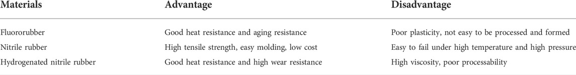
TABLE 1. Comparison of properties of different types of rubber materials.
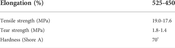
TABLE 2. Physical properties of nitrile rubber.
Rubber material is a typical nonlinear material, its elastic properties are related to hardness, load size, load frequency and other factors, therefore it cannot be represented by a simple elastic modulus. In the study of constitutive relation of rubber, the phenomenological theory is used to describe its stress-strain relation. It assumes that rubber is isotropic in undeformed state and considers rubber as an incompressible material, it is difficult to obtain a reasonable structure of the sealing unit through theoretical calculation when designing the structure of the rubber cylinder (Guo et al., 2011; Polonsky and Tyurin., 2015; Zhang et al., 2017). In the analysis and calculation of rubber components, the highly nonlinear and superplastic models include Mooney-Rivlin model, Yeoh model and Gent model. The applicability of these models is shown in Table 3.
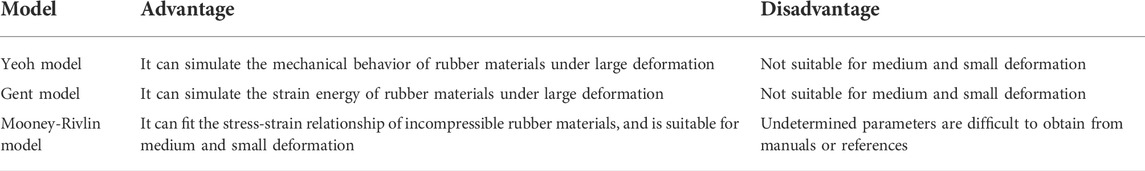
TABLE 3. Comparison of different constitutive models.
The Yeoh model and the Gent model cannot be used for moderate and small deformation, while the Mooney-Rivlin model can better fit the stress-strain relationship of incompressible rubber materials at moderate deformation. Therefore, the Mooney-Rivlin model is selected in this study.
The strain energy density function in the Mooney-Rivlin model is expressed as:
where W is the strain potential energy, I1 and I2 are the deformation tensors, and C10 and C01 are the Mooney material coefficients.
The Poisson’s ratio of incompressible rubber materials can generally be set to 0.5. When the rubber material is in the small strain region, the relationship between its elastic modulus E0, shear modulus G0 and material coefficient can be expressed as:
According to the fitting results of the experimental data of rubber hardness and elastic modulus, the relationship between rubber hardness H and elastic modulus E0 can be obtained:
From Eqs 2, 3, the relationship between hardness and material coefficient can be expressed as:
The ratio of C10 to C01 is usually between 0.3 and 0.7. In this study, C10/C01=0.5. The mechanical properties of the rubber material constitutive model are shown in Table 4.
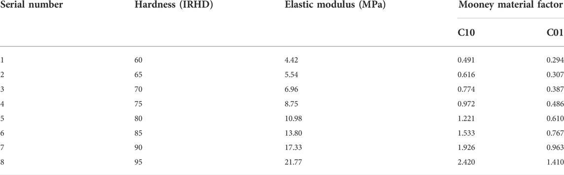
TABLE 4. Mechanical properties of rubber materials.
The finite element method is a principle of the finite element method, which uses an electronic computer to solve the numerical solution of problems such as static and dynamic characteristics of complex structures. It has high precision, strong adaptability and wide application range. At present, the finite element analysis software used to solve nonlinear material problems mainly includes ANSYS and ABAQUS.
ANSYS (Analysis System) is a large-scale CAE general finite element analysis software that integrates structure, heat, fluid, electromagnetic and acoustics, and has powerful and extensive geomechanical analysis functions. It is widely used in linear and nonlinear problems with multi-physical fields such as structure, heat, fluid, electromagnetic, acoustics, and multi-field coupling.
ABAQUS software is a relatively powerful finite element software in the field of engineering simulation, especially in solving complex nonlinear problems. The ABAQUS operation interface is simple and user-friendly, and complex problems can be “simplified” through the combination of various option blocks, so that highly nonlinear problems can be simulated.
Compared with ANSYS, ABAQUS adopts the parametric modeling method, which provides a powerful tool for parameter design and optimization of actual engineering structures and structural modification. Moreover, ABAQUS adopts CAD modeling and visualization window system, which has good human-computer interaction characteristics. Based on the above analysis, the ABAQUS software was selected for the nonlinear finite element analysis of the packer cylinder group in this study.
Different lithologic formations have different pore structures and rock mechanical properties. The scanning electron microscope images and rock mechanical parameters of typical mudstone, shale and sandstone of the artesian well formation in the study area are shown in Figure 2. Sandstone has the highest compressive strength and elastic modulus (uniaxial condition), followed by shale and mudstone, respectively. Cohesion represents the degree of aggregation between particles within a rock. The results show that loose mudstone has the lowest cohesion value, while sandstone with dense massive structure has the highest cohesion value.
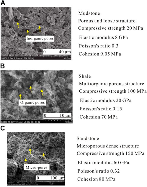
FIGURE 2. Microstructures of clastic rock formations of different types of lithology based on SEM observations. Notes: (A) Mudstone, Well S1, 2243 m; (B) Shale, Well S1, 2247 m; (C) Sandstone, Well S1, 2255 m.
Due to the different lithology of the formation, the packing performance of the packer and the formation is also different. Under the pressure environment of the downhole packer, the contact pressure between the rubber cylinder and the formation should be greater than the gas channeling pressure on either side, so that the gas channeling channel can be cut off. Only by ensuring that the upper or lower gas channeling cannot pass through the contact surface between the rubber cylinder and the formation, can the packer be able to absolutely effectively seal the upper and lower pressures. Therefore, as long as the contact pressure between the rubber cylinder and the well wall is greater than the pressure below the rubber cylinder, it can be determined that the rubber cylinder can effectively seal the upper and lower pressure differences in this case.
In this study, a parameter to characterize effective containment, the packer safety coefficient (S), was introduced. It is defined as the ratio of the maximum contact pressure of the packer cartridge to the pressure below the cartridge. It assumes that the pressure below the packer is greater than the pressure above it. If the obtained packing safety factor is greater than 1, it can be determined that the packer can effectively pack the upper and lower pressure difference in the downhole.
According to the lithological parameters in Figure 2, the casing material takes yield strength σ=835 MPa, elastic modulus E=210 GPa, and Poisson’s ratio μ=0.28. By keeping the pressure above the packer rubber cylinder at 40 MPa, the contact pressure between the packer and the formation can be calculated using finite element, under different lithologic formations and different pressure conditions below the rubber cylinder. The length of the rubber barrel is 0.8 m, and the interference thickness is 3 mm. The interference thickness is the value of the interference fit between the rubber cylinder and the formation after expansion. In turn, the containment safety factor is obtained (Figure 3).
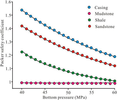
FIGURE 3. Relationship between the isolation safety factor and the pressure under the rubber cylinder.
Using the least squares fitting curve, the nonlinear mathematical model of the packing safety factor and the pressure under the packer can be obtained respectively under the formation conditions of casing, mudstone, shale and sandstone.
Casing:
Mudstone:
Shale:
Sandstone:
In above formulas, S is the packer safety coefficient; x is the pressure under the rubber cylinder, where 40 MPa < x < 60 MPa.
The above formulas (5–8) are empirical formulas established when the pressure below the packer rubber cylinder is 40–60 MPa. The application range of this empirical formula is further extended, that is, the pressure under the packer rubber cylinder is 40 ∼ x MPa (x≥40). When S=1, that is, when it can just be sealed, the maximum safe lower pressure of the rubber cylinder under the four models is calculated respectively: casing pT= 82.704 MPa > sandstone pS= 75.772 MPa > shale pY =60.988 MPa > mudstone pN= 44.28 MPa.
In order for the packer to achieve the expected packing effect in the downhole, it must be ensured that the rubber tube of the packer does not undergo stress damage under the downhole pressure difference. The stress of the rubber cylinder under different formation models was calculated by finite element analysis, and the results are shown in Figure 4.
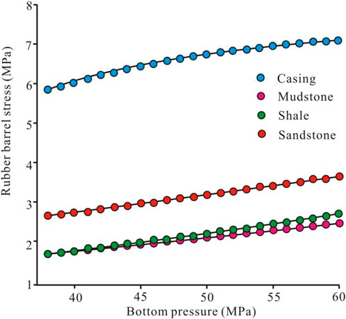
FIGURE 4. Variation curve of the isolation safety factor with the pressure under the rubber cylinder under different formation models.
After the least squares curve fitting, the nonlinear mathematical models of the maximum stress under the casing, mudstone, shale, and sandstone under the pressure of 40–60 MPa were obtained.
Casing:
Mudstone:
Shale:
Sandstone:
where σmax is the rubber barrel stress, MPa; x is the bottom pressure, MPa.
After the above calculation of the stress of the rubber cylinder, the maximum stresses in the above four formation models are 7.146, 2.575, 2.740 and 3.707 MPa, which are lower than the compression set strength of the rubber material of the rubber cylinder of 23.9 MPa. This means that the rubber cartridge will not be damaged by stress under the pressure (40 MPa<x <60 MPa) under the rubber cylinder. Therefore, when the pressure above the rubber cylinder is 40 MPa and the pressure below the rubber cylinder is 40–60 MPa, the packer can safely seal the upper and lower pressure differences.
The influence of the packer on the formation mainly refers to the influence of the contact pressure between the packer and the formation on the formation: ① If the contact pressure between the packer and the formation is too small, the packer cannot effectively seal the upper and lower pressure difference; ② If the contact pressure between the packer and the formation is too large, the formation or formation rock will be fractured and shear stress damage will occur.
This study assumes that only vertical wells are considered, and the effects of well inclination and azimuth on in-situ stress are ignored. Moreover, the horizontal in-situ stress is non-uniform, and the formation pore pressure is considered in the sandstone layer. Since the wellbore diameter is much smaller than the well depth, the vertical wellbore model can be simplified as a plane strain problem. That is, the maximum horizontal principal stress σH acts at infinite distance in the X direction, the minimum horizontal principal stress σh acts at infinite distance in the Y direction, the packer contact pressure P acts on the inside of the wellbore, and the sandstone has the effect of overlying rock pressure.
In this study, considering that the packer is driven to a depth of 4 000 m, the triaxial stress state of the rock in the downhole is σH = 30 MPa, σh = 20 MPa, and the overburden pressure is 40 MPa. Furthermore, under this assumption, the formation shear stress under different lithologic formations and under different contact pressures is calculated by the finite element method. Figure 5 shows the change curves of the maximum formation shear stress under different lithologic formations and different contact pressures. It can be seen from Figure 5 that the maximum shear stress of the borehole formation under the action of triaxial stress increases linearly with the increase of the contact pressure of the rubber.
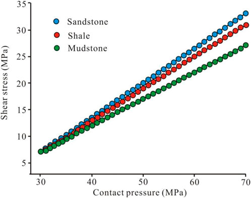
FIGURE 5. Variation of maximum formation shear stress under different contact pressures.
In addition, it can also be seen from Figure 5 that the straight line slope of the sandstone formation is the largest, followed by shale and mudstone. The slope represents the rate at which formation shear stress varies with packer contact pressure. Therefore, the maximum formation shear stress under different lithologic formations is proportional to the increasing rate of the packer contact pressure and the elastic modulus of the formation.
Thus, the relational models of formation shear stress and contact pressure under different lithologic formations and under different contact pressures are established.
Sandstone:
Shale:
Mudstone:
where τ is the formation shear stress, MPa; p is the contact stress, MPa.
These models can be used to calculate the maximum safe contact pressure for shear stress failure in different lithologic formations. It provides the basic conditions for the structural optimization of the packer.
In order to verify the sealing performance and bearing capacity of the compression packer, the basic size parameters and setting pressure of the packer cartridge are calculated as follows:
In order to facilitate installation and interchangeability, the inner diameter of the rubber barrel should be larger than the outer diameter of the central pipe, and it should contact and close the well wall quickly during the setting process. Therefore, the gap between the rubber barrel and the central tube should not be too large. The outer diameter of the central tube was 35 mm, and the inner diameter of the rubber cartridge was determined to be 35.5 mm.
The height of the rubber barrel determines the contact length between the rubber barrel and the hole wall, which is an important factor in determining the sealing performance. The relevant empirical formulas are:
In the formula, σz is the axial stress of the rubber tube; E is the elastic modulus of the rubber tube material; μ is the Poisson coefficient; R3 is the inner diameter of the casing; R2 is the outer diameter of the rubber tube; R1 is the inner diameter of the rubber tube; h is the rubber The height of the pipe; f is the friction coefficient; [τ] is the allowable shear force of the rubber cylinder; A is the annular cross-sectional area between the central pipe and the well wall.
Since R3=76 mm, R2=72 mm, R1=35.5 mm and ΔP=35 MPa, the axial stress and the height of the rubber cylinder can be calculated: Fε=19.11 kN and h=100 mm.
The differential equation of radial displacement of elastic body is expressed as:
where u is the radial displacement and r is the radius of curvature.
Its general solution can be expressed as:
where u is the radial displacement and r is the radius of curvature.
According to the boundary conditions, the definite integral can be calculated as:
Therefore,
In the formula, R3 is the inner diameter of the casing, R2 is the outer diameter of the rubber cylinder, and R1 is the inner diameter of the rubber cylinder.
Substituting Eqs 22, 23 into the definite integral (20), the relative radial elongation εr and relative tangential elongation εθ can be obtained:
where u is the radial displacement, r is the radius of curvature, R3 is the inner diameter of the casing, R2 is the outer diameter of the rubber cylinder, and R1 is the inner diameter of the rubber cylinder.
The change in volume of an elastomer θ can be expressed as:
where εz is the relative axial elongation, εr is the relative radial elongation and εθ is the relative tangential elongation.
Assuming that the sealing element is incompressible, that is, θ=0, Eq. 26 can be expressed as:
where εz is the relative axial elongation, εr is the relative radial elongation and εθ is the relative tangential elongation.
Substituting Eqs 24, 25 into Eq. 27, the relative axial elongation εs can be obtained:
where R3 is the inner diameter of the casing, R2 is the outer diameter of the rubber cylinder, and R1 is the inner diameter of the rubber cylinder.
According to generalized Hooke’s law, radial, tangential, and axial normal components can be calculated:
where εz is the relative axial elongation; εr is the relative radial elongation; and εθ is the relative tangential elongation; σr is the radial stress; σθ is the radial stress; σz is the radial stress; μ is the Poisson’s coefficient; E is the elasticity modulus.
Further, the above three expressions can be transformed into:
where R3 is the inner diameter of the casing; R2 is the outer diameter of the rubber cylinder; R1 is the inner diameter of the rubber cylinder; εz is the relative axial elongation; εr is the relative radial elongation; εθ is the relative tangential elongation; σr is the radial stress; σθ is the radial stress; σz is the radial stress; μ is the Poisson’s coefficient; E is the elasticity modulus.
Substitute Eq. 34 into
where R3 is the inner diameter of the casing; R2 is the outer diameter of the rubber cylinder; μ is the Poisson’s coefficient; E is the elasticity modulus.
By analyzing the relationship between the force and deformation of the rubber cylinder under uniaxial compression, the equilibrium conditions of the force can be obtained:
In the formula, ΔP is the packer pressure difference; A2 is the annular cross-sectional area between the packer center pipe and the well wall; f is the friction coefficient; Pk’ and Pk are the pressures of the axial load acting on the inner and outer surfaces of the rubber cylinder; S1 and S2 are the lateral areas of the inner and outer sealing surfaces after the rubber tube is deformed.
The simplified calculation is as follows:
where Pk’ and Pk are the pressures of the axial load acting on the inner and outer surfaces of the rubber cylinder; S1 and S2 are the lateral areas of the inner and outer sealing surfaces after the rubber tube is deformed.
Therefore,
where S1 and S2 are the lateral areas of the inner and outer sealing surfaces after the rubber tube is deformed; R1 is the inner diameter of the rubber cylinder; h is the height of rubber tube.
Substituting Eq. 28 into Eq. 39, it can be transformed into
where R3 is the inner diameter of the casing; R1 is the inner diameter of the rubber cylinder; ΔP is the packer pressure difference; f is the friction coefficient; h is the height of rubber tube; εz is the relative axial elongation.
At the same time, when the axial load acts on the inner and outer sealing surfaces of the rubber cylinder, the radial pressure and the axial pressure are equal:
where F is the total compressive force; R1 is the inner diameter of the rubber cylinder; R2 is the outer diameter of the rubber cylinder;
The compressive load required for the packer to work in a sealed state is:
where ΔP is the packer pressure difference; R3 is the inner diameter of the casing; R2 is the outer diameter of the rubber cylinder; R1 is the inner diameter of the rubber cylinder; f is the friction coefficient; h is the height of rubber tube; εz is the relative axial elongation.
By substituting the known database into the above formula, the relative axial elongation εs, the compressive load FΔP in the sealed state, the compressive force Fε in the plane deformation and the total compressive force F can be obtained:
Furthermore, the pressure on the cartridge unit:
where S is the stress area of the total compressive force, mm2; P is the pressure on the cartridge unit, MPa.
The compression packer” is one that compresses the packer by axial force and enlarges the diameter of the packer to seal it. It's widely applicable and can be used in various conditions of deep Wells, ultra-deep Wells, directional Wells, horizontal Wells and window-side drilling. The compression packer cartridge consisting of two cartridges in this paper was selected as the study object. Its overall structure consists of a connecting device, a setting device, an anti-midway setting device, a locking device, a sealing device, etc., (Figure 6). The working principle is as follows: the piston and the central pipe are connected by threads, and the inner and outer sides are sealed with the central pipe and the liquid cylinder respectively through O-rings. When working, the piston is fixed on the central tube, and the high-pressure liquid enters the cylinder through the central small hole between the piston and the liquid cylinder. In turn, it pushes the cylinder to the left and forms a seal condition in the compressed rubber cartridge.
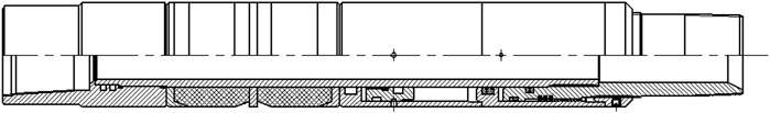
FIGURE 6. Schematic of a compression packer.
The structure of the rubber cylinder is shown in Figure 7. The difference from the general packer is that it has an anti-protrusion structure and adopts steel with lower rigidity. Compared with red copper, it reduces the cost, in addition, it can use the radial extension of the rubber barrel to closely contact the outer diameter of the rubber barrel, thereby effectively preventing the possibility of shoulder protrusions. Therefore, it improves the contact stress between the rubber cylinder and the pipe wall, and ensures the good sealing performance of the packer.
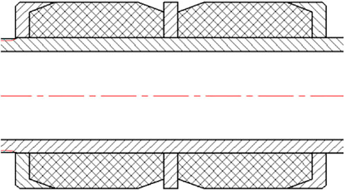
FIGURE 7. Schematic diagram of the rubber barrel structure.
The direct contact between the rubber barrel and the casing will directly lead to structural deformation and performance degradation of the rubber hose, especially under high temperature and high pressure. Therefore, the existence of an anti-shoulder structure is very necessary. A new type of anti-shoulder structure is designed using the conical surface shape of the double rubber cylinder. The structure is shown in Figure 8, and its working principle is shown in Figure 9.

FIGURE 8. Schematic diagram of the shoulder pad structure.
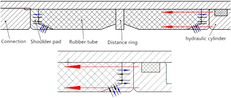
FIGURE 9. Schematic diagram of the rubber barrel structure.
The material used for the shoulder pads is low-strength steel. Its low stiffness allows a slight radial deformation of the cartridge, thereby effectively reducing contact stress, and reducing the possibility of cartridge failure and effectively preventing shoulder protrusions. Furthermore, the contact stress between the rubber cylinder and the pipe wall is increased, which ensures the good sealing performance of the packer.
The finite element software ABAQUS contains most constitutive models of hyperelastic materials. In the Mooney-Rivlin model selected in this paper, C01 = 0.610, C10 = 1.221. The mechanical parameters of the key components of the packer are shown in Table 5.
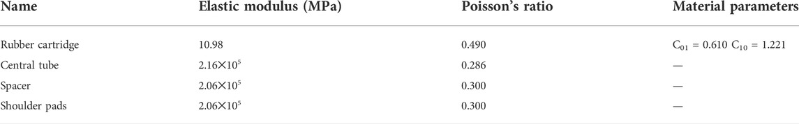
TABLE 5. Mechanical parameters of materials in key parts of packer.
In the process of finite element analysis, the following assumptions are made in this study without affecting the use function of the packer:
① The packer is located in the center of the wellbore before and after setting, and is symmetrical about the centerline of the bottom hole;
② The effect of the packer’s own weight on the results is ignored;
③ The influence of the irregularities of the wellbore on the analysis is ignored, and the casing is used instead of the wellbore to conduct the test;
④ In the analysis, only the part of the rubber cylinder is taken, the lower spacer ring, the central pipe and the well wall are fixed, and only the rubber cylinder is compressed.
The finite element analysis mainly analyzes the deformation of the rubber cylinder. Since both the spacer ring and the center tube are alloy steel, the elastic modulus is large, so the distance ring and the center tube are set as rigid bodies. According to the structure and size of the rubber cylinder in the assembled state, the contact design between the rubber tube and the metal part is established: the outer tube and the inner ring are fixed, the lower shoulder pad is fixed, and the upper shoulder pad is set as the loading reference point. The finite element model of the rubber tube was established by the finite element analysis software ABAQUS. The material of the central tube is 42CrMo, the Young’s modulus and Poisson’s ratio are 2.16e5 MPa and 0.286, respectively; the casing material is 45 steel, the material of the anti-outburst ring is 20 steel, the Young’s modulus and Poisson’s ratio are both 2.06e5 MPa and 0.3. The cartridge material parameters are designed to be C01 = 0.610, C10 = 1.221. The solid model is shown in Figure 10.
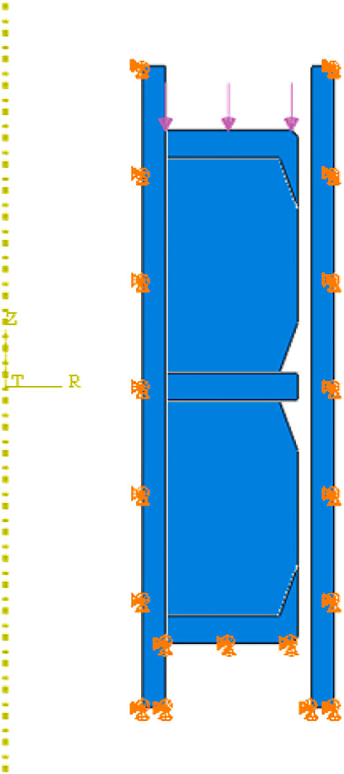
FIGURE 10. Finite element model of rubber cartridge.
The axial load of the rubber cartridge is 13.05 MPa (from Figure 8), and the bottom and lower shoulders of the model are restrained. The deformation, stress and contact stress cloud of the rubber cylinder are shown in Figure 11. In the deformation cloud, it can be seen that the stress is evenly distributed on the gluing cylinder. The cartridge is in close contact with the casing without excessive stress concentration. This shows that the anti-shoulder structure can make the stress uniform, and it also meet the energy requirements of the structure using low-strength steel. Its proper deformation makes the deformation degree of the rubber cartridge more elastic.
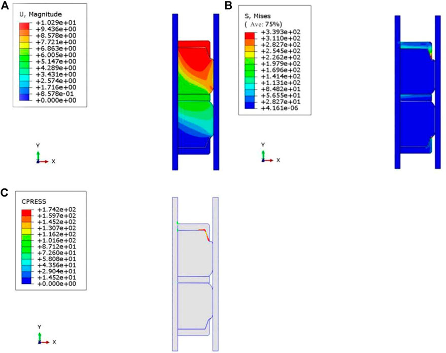
FIGURE 11. Simulation results of the stress distribution of the rubber cylinder. Notes: (A) Deformation cloud of the rubber cylinder; (B) Stress cloud of the rubber cylinder; (C) Contact stress cloud of the rubber cylinder.
The contact pressure curve is shown in Figure 12. On the contact pressure curve, the maximum contact stress is near the two shoulder guards, and the contact pressure on the rubber tube is very uniform. Therefore, the rubber tube is protected by shoulder guards at both ends, thereby ensuring the structural integrity and uniformity of the force of the rubber tube. According to the stress cloud calculation results, the packer does not reach the maximum safe contact pressure when the lithological stratum is damaged by shear stress in the contact stratum.
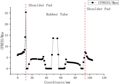
FIGURE 12. Contact stress curve of the rubber cartridge.
In this study, in order to optimize the sealing performance of the conventional compression packer, the packing performance of the packer and the formation was systematically studied according to the different lithology of the formation. Empirical equations for packer suitability under three formation conditions were derived. A new anti-shoulder protrusion device is designed by comparing the commonly used rubber materials for packers and constitutive models. The main conclusions obtained in this paper are as follows:
1) The maximum stress of the rubber cylinder in the three formation models of mudstone, shale and sandstone is lower than the compression set strength of the rubber cylinder, indicating that the rubber cylinder will not cause stress damage.
2) At the same time, by analyzing the common rubber materials and constitutive models of packers, the structure of the packer rubber cylinder and a new anti-shoulder protrusion device were redesigned. Nitrile-butadiene rubber (NBR) meets the performance requirements of the rubber tube under the allowable pressure difference and temperature difference. The designed new anti-protrusion device can ensure the structural integrity and stress uniformity of the rubber tube, thereby ensuring good sealing performance.
3) Under the three formation conditions of mudstone, shale and sandstone, the rubber cartridge can be in a safe working state, and its sealing width is close to the contact length of the rubber cartridge. In addition, the rubber cartridge is in a good elastic deformation range.
4) The design of the packer in this study satisfies the third strength theory and safety requirements, the deformation and sealing performance of the rubber cylinder are relatively stable, and the size of the rubber cylinder also meets the field requirements.
The original contributions presented in the study are included in the article/supplementary material, further inquiries can be directed to the corresponding authors.
Authors YK and ZL are responsible for the idea and writing of this paper and authors TK, ZR, TS, and XZ are responsible for the simulation.
This work was supported by Special funding support for the construction of innovative provinces in Hunan Province No. 2019GK1012, China.
The authors declare that the research was conducted in the absence of any commercial or financial relationships that could be construed as a potential conflict of interest.
All claims expressed in this article are solely those of the authors and do not necessarily represent those of their affiliated organizations, or those of the publisher, the editors and the reviewers. Any product that may be evaluated in this article, or claim that may be made by its manufacturer, is not guaranteed or endorsed by the publisher.
Akhtar, M., Qamar, S. Z., Pervez, T., Khan, R., and Al-Kharusi, M. (2012). Elastomer seals in cold expansion of petroleum tubulars: Comparison of material models. Mater. Manuf. Process. 27 (7), 715–720. doi:10.1080/10426914.2011.648036
Bu, Y., Ma, M., and Li, J. (2011). Study on sealing property criterion and structure design method of packer. Lubr. Eng. 36 (11), 75–78. doi:10.1002/clc.20818
Dorokhov, M., Kostriba, I., and Biletskyi, V. (2016). Experimental research on the sealing ability of borehole packers. Eastern-European J. Enterp. Technol. 4, 56–62. doi:10.15587/1729-4061.2016.74831
Guo, Z., Li, Q., and Wang, Y. (2011). “Analysis and structural improvement of the rubber part in packer in a way of non-linearity finite element,” in 2011 Second International Conference on Mechanic Automation and Control Engineering, Inner Mongolia, China, 15-17 July 2011 (IEEE), 73–76. doi:10.1109/MACE.2011.5986860
Huang, Y., Li, Y., Zhao, H., and Wen, H. (2020). Research on constitutive models of hydrogenated nitrile butadiene rubber for packer at different temperatures. J. Mech. Sci. Technol. 34 (1), 155–164. doi:10.1007/s12206-019-1217-x
Lan, W., Wang, H., Zhang, X., and Chen, S. S. (2019). Sealing properties and structure optimization of packer rubber under high pressure and high temperature. Pet. Sci. 16, 632–644. doi:10.1007/s12182-018-0296-0
Li, Z., Liu, J., and Ding, Y. (2013). Finite element analysis of the packer at fracturing. Appl. Mech. Mater. 385-386, 159–162. doi:10.4028/www.scientific.net/AMM.385-386.159
Liu, H., Zhang, W., Cao, Y., and Dou, Y. (2020). Analysis of the performance improvement effect of combined packing for oil and gas well packer. IOP Conf. Ser. Earth Environ. Sci. 514, 022017–22025. doi:10.1088/1755-1315/514/2/022017
Liu, J., Mei, L., Ding, W., Xu, K., Yang, H., and Liu, Y. (2022). Asymmetric propagation mechanism of hydraulic fracture networks in continental reservoirs. GSA Bull. doi:10.1130/B36358.1
Liu, Z., Hu, Z., Liu, G., Liu, Z., Liu, H., Hao, J., et al. (2021). Pore characteristics and controlling factors of continental shale reservoirs in the Lower Jurassic Ziliujing Formation, northeastern Sichuan Basin. Oil Gas Geol. 42 (1), 136–145. doi:10.11743/ogg20210112
Luo, R. K., Zhou, X., and Tang, J. (2002). Numerical prediction and experiment on rubber creep and stress relaxation using time-dependent hyperplastic approach. Polym.D. Snoke, Sci. 298, 1368. doi:10.1016/j.polymertesting.2016.03.026
Polonsky, V. L., and Tyurin, A. P. (2015). Design of packers for sealing of the inter-tube space in equipment used for recovery of oil and gas. Chem. Pet. Eng. 51 (1-2), 37–40. doi:10.1007/s10556-015-9994-2
Wakuda, M., Yamauchi, Y., and Kanzaki, S. (2002). Effect of workpiece properties on machinability in abrasive jet machining of ceramic materials. Precis. Eng. 10, 193–198. doi:10.1016/S0141-6359(01)00114-3
Yohannes, Y. (2017). Hydraulic in situ testing for mining and engineering design: Packer test procedure, preparation, analysis and interpretation. Geotech. Geol. Eng. (Dordr). 35, 29–44. doi:10.1007/s10706-016-0112-9
Zhang, G., Zhang, Z., and Xin, Y. Y. (2017). Creep and stress relaxation of pine material polyethylene. Adv. Eng. Sci. 2, 232–239. doi:10.15961/j.jsuese.201601123
Zhao, P., He, B., Zhang, B., and Liu, J. (2022). Porosity of gas shale: Is the NMR-based measurement reliable? Petroleum Sci. 19 (2), 509–517. doi:10.1016/j.petsci.2021.12.013
Zhao, P., Xie, L., Fan, Z., Deng, L., and Liu, J. (2021b). Mutual interference of layer plane and natural fracture in the failure behavior of shale and the mechanism investigation. Pet. Sci. 18 (2), 618–640. doi:10.1007/s12182-020-00510-5
Zhao, P., Xie, L., He, B., and Liu, J. (2021a). Anisotropic permeability influencing the performance of free CH4 and free CO2 during the process of CO2 sequestration and enhanced gas recovery (CS-egr) from shale. ACS Sustain. Chem. Eng. 9 (2), 914–926. doi:10.1021/acssuschemeng.0c08058
Keywords: fracturing, packer, structural optimization of rubber cylinder, finite element analysis, performance optimization
Citation: Kang Y, Long Z, Kang T, Ren Z, Shi T and Zhang X (2022) Adaptability of hydraulic fracturing packers and optimization of their sealing performance for three common clastic rock reservoirs based on finite element analysis. Front. Earth Sci. 10:986344. doi: 10.3389/feart.2022.986344
Received: 05 July 2022; Accepted: 04 August 2022;
Published: 29 August 2022.
Edited by:
Jingshou Liu, China University of Geosciences Wuhan, ChinaCopyright © 2022 Kang, Long, Kang, Ren, Shi and Zhang. This is an open-access article distributed under the terms of the Creative Commons Attribution License (CC BY). The use, distribution or reproduction in other forums is permitted, provided the original author(s) and the copyright owner(s) are credited and that the original publication in this journal is cited, in accordance with accepted academic practice. No use, distribution or reproduction is permitted which does not comply with these terms.
*Correspondence: Yusen Kang, ODY5MjgwNTk0QHFxLmNvbQ==; Zhilin Long, bG9uZ3psQHh0dS5lZHUuY24=
Disclaimer: All claims expressed in this article are solely those of the authors and do not necessarily represent those of their affiliated organizations, or those of the publisher, the editors and the reviewers. Any product that may be evaluated in this article or claim that may be made by its manufacturer is not guaranteed or endorsed by the publisher.
Research integrity at Frontiers
Learn more about the work of our research integrity team to safeguard the quality of each article we publish.