 Hao Yuan
 Taoli Xiao*
- School of Urban Construction, Yangtze University, Jingzhou, China
In the study of pre-fabricated single-fissured rock, the failure mode, mechanical properties and propagation law of rock are affected by the length and inclination angle of fissure. In this study, artificially prepared marble-like rocks with different fissure characteristics were used as rock representatives, using PFC2D software to establish a uniaxial compression model tests for rocks with fissures. The effects of different fissure lengths and inclination angles on the failure mode and crack initiation and propagation of rock-like structures were systematically studied, revealing the mechanism of macroscopic mechanical behavior of rocks containing single fissures in the process of crack initiation, propagation, and failure at the micro-level. The results show that: 1) Failure mode of the rock sample is mainly controlled by fissure inclination angle and fragmentation degree is mainly controlled by fissure length. 2) The initiation stress, damage stress, and peak stress of rock samples during loading deformation increase with the increase of fissure inclination angle, and decrease with the increase of fissure length. The crack initiation angle decreases with the increase of the fissure inclination angle. 3) Crack initiation characteristics: at a low fissure inclination angle (α< 45°), the crack initiation position has a certain offset to the center of the prefabricated fissure, or starts from the tip of the prefabricated fissure. At high fissure inclination angles (α≥45°), the crack initiates from the tip of the prefabricated fissure and forms a “dispersed” distribution. 4) The crack propagation law is mainly shear cracks, at a low fissure inclination angle (α< 45°), the crack propagation has obvious aggregation band formation. At high fissure inclination angles (α≥45°), the crack aggregation zone gradually weakened and expanded in the direction of dispersion.
1 Introduction
Fissured rock is the most common geotechnical medium in related engineering fields, such as civil water conservancy, mining, oil and gas extraction, and nuclear waste storage. It is a product of the long and complex diagenetic process of rock formation and is also the core subject of concern in the design, construction, and operation period of geotechnical engineering facilities. Engineering practices have highlighted that the instability of fissured rock is usually affected by the initiation, expansion, and spread of internal fissures in the rock, which reduces the mechanical properties of the rock, causing safety instability in rock structures and facilities. The inclination angle of the fissure and the length of the fissure in the rock (Shu et al., 2016) play a crucial role in the initiation and propagation of cracks in the rock, which in turn affects their mechanical behavior and mechanical properties. Therefore, studying the characteristics of fissure initiation, propagation, penetration, and failure in rocks, as well as their mechanical behavior, provides a significant theoretical basis for revealing the mechanism of rock damage and failure modes.
Recently, numerous scholars have conducted extensive research on the mechanical properties, initiation, propagation, and evolution of rocks with various fissures. A.V. Dyskin et al. (2003) conducted uniaxial compression tests on samples with single fissure of different shapes and sizes, and found that the propagation of 3-D cracks was different from that of 2-D cracks during compression. Unlike 2-D cracking, there were intrinsic limits on 3-D growth of wing cracks produced by a single pre-existing fissure. Wei et al. (2020) considered the effect of fluid pressure on rock with single fissure, and found that with the increase of fluid pressure, the propagation of wing cracks was accelerated, the propagation of secondary cracks was inhibited, the peak stress of the sample was reduced, and causes the specimen to undergo tensile failure. Fu et al. (2013) conducted uniaxial compression tests on elliptic three-dimensional specimens with built-in single fissure, and found that wrapped wing cracks and petal-shaped cracks appeared in the process of crack propagation, and finally a vertical curved tension crack was generated at the front of the petal-shaped crack to split the specimen. Zhang and Wong (2012) used PFC to establish uniaxial compression test of rock-like with single fissure, systematically studied the influence of fissure inclination angle on crack propagation, and found that with the increase of fissure inclination angle, the tensile force concentration zone shifted from the middle of the fissure towards the fissure tip regions as fissure inclination angle increased. Some scholars (Li and Li, 2013; Zhang et al., 2017) conducted numerical simulations on the failure process of rock samples with two parallel fissures and analyzed the influence of the rock bridge inclination angle and fissure inclination angle on the crack evolution characteristics of rock samples. A. BOBET and H. H. EINSTEIN (1998) conducted uniaxial and biaxial compression tests on rock-like materials with double fissures, and found that the interaction distance between cracks could reach 1.5 times of the fissure length during the crack growth process. In addition, only when the fissures were close enough to each other could they coalescence, and this distance decreased with the increase of confining pressure. In addition, scholars (Pan, 2017; Tian et al., 2017; Sarfarazi et al., 2018; Chen et al., 2020; Wang Z. et al., 2020) have also performed numerical simulations of uniaxial compression on two coplanar fissured rocks and reported that the peak strength generally increased with the inclination angle of the two coplanar fissures, and revealed that the failure modes of the two coplanar fissured rocks were primarily macroscopic shear failure modes and macroscopic tension-shear composite failure modes. Lou et al. (2019) investigated the effect of the fissure inclination angle on the energy evolution law of a rock mass through uniaxial cyclic loading and unloading tests. Niu et al. (2016) adopted the improved rigid-body spring element method to numerically simulate the compressive failure process of fissured specimens with different opening degrees and found that the peak strength of the specimens first increased before decreasing with an increase in the fissure opening degree, and finally remained stable. Mi (2020) studied the crack-propagation law of single and double fissures under hydraulic pressure. Many scholars have also studied the rock mass containing multiple fissures. Zhou et al. (2019a, 2019b), Wang et al. (2018) analyzed the influence of brittleness of rock-like materials on crack initiation, propagation, and coalescence behaviors in three fissure-contained specimens through uniaxial compression test and DIC, and found that crack initiation mode transforms from the tensile mode to the shear mode with a decrease in the brittleness index of rock-like materials. Zhou et al. (2013); Zhou et al. (2021) conducted uniaxial compression tests on rock-like materials with four fissures and revealed five types of cracks, including wing cracks, quasi-coplanar secondary cracks, oblique secondary cracks, out-of-plane tensile cracks and out-of-plane shear cracks. Zhou et al. (2018) conducted uniaxial compression tests on rock samples with nine prefabricated fissures, and combined with DIC, revealed the failure mechanism of brittle and ductile multi-fissured rock mass. The results show that the crack initiation mode transforms from shear crack to tensile crack as the brittleness index. Wang Q et al. (2020) conducted uniaxial compression tests on granite specimens with central holes and hole edge fissures, and found that the mechanical properties of specimens such as strength are greatly weakened by the central hole and hole edge fissures compared with those of intact specimens, and the weakening effect decreases gradually with the increase of fissure inclination angle. In addition to the effect of the fissures itself on the specimen, some scholars have considered the effect of external factors on the mechanical properties and the law of crack propagation of fissured rock mass. Zhao et al. (2019) studied the rheological fracture behavior of rock by establishing a simple and practical rheological fracture model under the combined action of hydraulic pressure and far-field stress, and found that both transient crack propagation and subcritical crack propagation increased with an increase in the hydraulic pressure. Zhao et al. (2020) studied the influence of acid solution on fracture toughness and subcritical crack growth of marble, lherzolite, and amphibolite. The results indicate that, for all three studied rocks, the percentage of load drop during RLX increases and the fracture toughness decreases when the environmental condition changes from air to distilled water and to an acidic solution with higher acidity. Zhao et al. (2021) proposed a dual-medium model, including equivalent continuous and discrete fissure media to study the coupled seepage-damage effect in fissured rock masses, and found that in the process of water injection in coal seam, the damage zone and major fracture apertures in the coal seam gradually increase with increasing injection time. Some scholars have also used particle flow code (PFC) to simulate various rock defect shapes and found the PFC has a good simulation effect on revealing the rock failure mode, microscopic mechanism of fissure propagation, and the degradation behavior of mechanical properties. Zeng et al. (2021) used PFC to simulate the uniaxial compression of rocks with double-cavity and double-fissure defect rock and analyzed the influence of the fissure inclination angle and defect shape on rock mechanical properties and the final failure mode. Li et al. (2020) employed PFC to simulate the uniaxial compression of a porous trigeminal fissure specimen and summarized the influence of the fissure inclination angle, hole diameter, and length of the fissure on the mechanical properties of the rock mass. In terms of fracture geometry, Wang Y et al. (2020) performed a uniaxial compression simulation test on composite rock samples containing a single fissure. The authors explored the effect of the fissure inclination angle and length of the fissure on rock mechanical properties and failure mode, and reported that the larger the fissure inclination angle or fissure length, the smaller the fissure expansion range on the side with relatively weak mechanical properties in the composite rock sample, and the failure mode exhibited ‘X’ → ‘y’→ ‘>’ transition change characteristics. Zhang et al. (2019) analyzed the influence of the comprehensive effect of the fissure inclination angle, length of the fissure, and position of the fissure on the strength and failure characteristics of the rock, and they discovered that the inclination angle of the fissure has a significant effect on the initiation position and initiation time of the new crack; the length of the fissure is related to the integrity and stability of the rock; the fissure position can affect the scale of crack propagation and failure form; and the degree of influence on peak strength from high to low is length, inclination angle, and position. Xi et al. (2020) performed uniaxial compression tests on granite with a pre-fabricated fissure and found that wing cracks expanded more rapidly as the inclination angle of the fissure increased, and new cracks were distributed clockwise. Li et al. (2012) also conducted a simulation test on a rock with a pre-fabricated fissure and found that the inclination angle of the fissure had a significant influence on the crack initiation position, crack initiation angle, and crack initiation sequence.
In summary, most of the research results are analyzed from a macroscopic perspective, and the research focuses on the number and shape of prefabricated fissures. Due to the experimental limitations and the complexity of rock texture, details of the cracking processes could not always be observed and assessed comprehensively. Therefore, this paper analyzes the crack propagation law of rock samples in the process of failure from the perspective of combining macro and micro. In this study, artificial marble-like rocks with different fissure sizes and distribution characteristics were used as representative rock samples and combined with uniaxial compression tests and particle flow simulations to explore the failure characteristics and crack propagation process of a single fissure rock. First, the particle flow PFC2D software was employed to establish the model sample and internal particles, fissure, and contact conditions. Combined with the laboratory test parameters, the physical and mechanical parameters of the model sample were established using a trial-and-error method. Second, the ultimate failure mode and peak stress of rock samples were obtained through an indoor uniaxial compression test and PFC2D numerical simulation, and the variations in the failure mode and peak stress with the fissure inclination angle and fissure length were discussed. Finally, based on the PFC2D numerical simulation method, the variation law and internal relationship of the fissure initiation angle, initiation stress, and damage stress with the fissure inclination angle and fissure length were determined.
2 Uniaxial compression test of rock with single fissure
2.1 Test setup
In the uniaxial compression test of fissured rock samples, a large number of rock samples are required to study the propagation process and evolution law of defects, such as crack initiation, propagation, and failure. However, it is difficult to obtain rock samples with the same or similar fissure lengths and inclination angles in site sampling, which makes it difficult to adhere to the needs of a large number of engineering tests in practice. Therefore, it is necessary to artificially prepare single-fissured samples with different fissure scales and distribution characteristics as representative rock samples to analyze the failure characteristics and influencing factors of single-fractured rock (Xiao et al., 2012). Taking the pre-fabricated marble-like artificial rock samples as the research object, the mass ratio is 425#ordinary Portland Cement: Silica fume: Quartz sand: Iron powder: Superplasticizer: Water = 1∶0.13∶0.8∶0.25∶0.01∶0.4. According to the test method outlined by the International Society for Rock Mechanics and Rock Engineering, the rock sample was pre-fabricated into a cylinder with a height of 100 mm and diameter of 50 mm, and fissures with different lengths (L) and inclination angles (
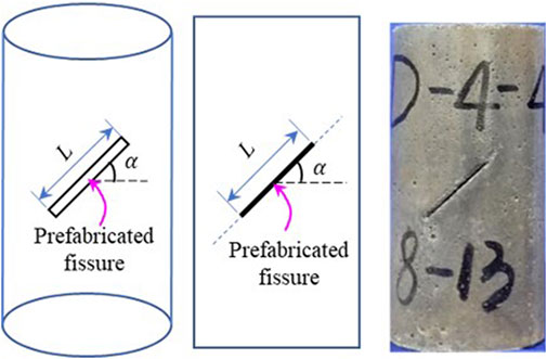
FIGURE 1. Configuration distribution of fissure.
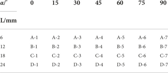
TABLE 1. Marble samples setting with prefabricated fissured.
2.2 Establishment of PFC2D numerical model
In contrast to the continuum mechanics method, the PFC numerical simulation method is more suitable for analyzing the mechanical properties and behavior of a medium containing defects. The principle is that the sample is simulated by the collection of round particles. Subsequently, the damage evolution and macroscopic mechanical behavior of the material are simulated by the movement and interaction of the particles. The numerical test was divided into two steps: sample preparation and loading. The PFC2D software was used to produce uniformly distributed particles within a certain range to simulate the sample. The size of the model sample was the same as that of an actual rock sample. A fissure was generated using the particle deletion method. The fissure length was 24 mm and the fissure inclination angle was 60°, as depicted in Figure 2A. The sample was locally enlarged to clarify the contact type between particles more clearly, as shown in Figure 2C. Model loading involves the application of concentrated loads of the same size and opposite directions to the upper and lower walls and simulates the loading process of the uniaxial compression test at a certain loading speed. When the post-peak strength is equal to 70% of the peak strength, the loading stops, and the program records the data in real time during the entire process.
FIGURE 2. Fissured rock PFC2D model. (A) Model sample, (B) local amplification and (C) particle contact type.
The test adopted the built-in flat joint model (FJM), in which the number of particles in the model sample was 12,952 in total, and there were 32,379 contact points between particles. According to the existing research results on the loading rate (Huang et al., 2012; Chen, 2018), the loading of the test was simulated at a loading rate of 0.04 m/s. Based on the indoor test parameters, the trial-and-error method was adopted to adjust the mesoscopic parameters of the model so that the stress-strain curve of the numerical simulation was consistent with the laboratory test curve, as depicted in Figure 3. The physical and mechanical parameters of the model sample determined in this study are listed in Table 2.
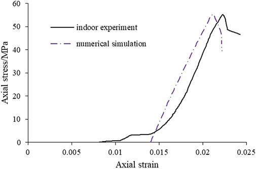
FIGURE 3. Comparison of stress-strain curves between laboratory test and numerical simulation.
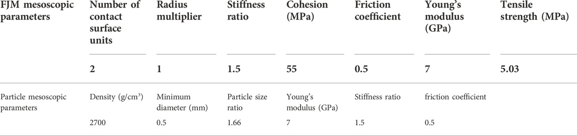
TABLE 2. Parameters for model setting.
2.3 Numerical simulation and laboratory test failure analysis of rock with a single fissure
2.3.1 Peak stress comparative analysis
According to the numerical model parameters listed in Table 2, the final failure mode of the fissured rock sample in the indoor uniaxial compression test was compared with the final failure mode diagram simulated by PFC2D. The failure modes of rock samples change with the fissure inclination angle under the same fissure. Thus, the lengths are different, and the failure modes with the change in fissure length under the same fissure inclination angle are the same. Therefore, two groups of pre-fabricated samples with fissure lengths of 12 and 18 mm were selected for the failure modes at different fissure inclination angles. The peak stress of the rock samples was obtained from an indoor uniaxial compression test and PFC numerical simulation test, as shown in Figure 4.
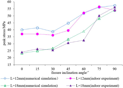
FIGURE 4. Comparison of peak stress between numerical and laboratory tests with different fissure lengths.
From Figure 4, it can be observed that the peak stress of the PFC numerical simulation is consistent with the numerical value measured by the indoor uniaxial compression test, indicating that the PFC simulations of the fissured rock uniaxial failure test are consistent with each other, indicating the feasibility of the method. When the fissure length is constant, the peak stress of the rock sample is close when α≤30°, indicating that when the fissure inclination angle is low, the rock strength is less affected by the change in the inclination angle. When α≥30°, the peak stress of the specimen increases with an increase in the inclination angle, and when α is close to 90°, the peak stress growth rate will slow down. In the meantime, comparing the fissure lengths of 12 mm and 18 mm, it was revealed that with the increase in fissure length, the peak stress will be significantly reduced, particularly at a low fissure inclination angle; that is, at α≤45°, the peak stress of the 18 mm specimen will decrease to 60% of the peak stress of the 12 mm sample, indicating that the fissure length has a significant influence on the strength of the rock sample. When
2.3.2 Comparative analysis of failure modes
The final failure modes of the specimens obtained from the indoor uniaxial compression test and PFC numerical simulation were compared and analyzed, as illustrated in Figure 5. The failure mode diagram uses different colored lines to distinguish the propagation of cracks in different ways; more specifically, the thick red line represents the location of the pre-fabricated crack, the green line represents the crack extending from the tip of the pre-fabricated fissure to the upper and lower ends of the sample, the orange lines represent the cracks that expanded from the middle of the pre-fabricated crack to the upper and lower ends of the sample, and the blue lines represent the cracks that expanded from the upper or lower ends of the sample.
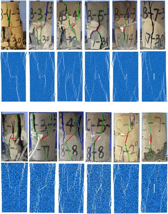
FIGURE 5. Rock samples failure modes of test and numerical simulation with different fissure lengths and inclination angles.(A) L=12 mm (B) L=18 mm.
It can be observed from Figure 5A that under the same fissure length when α= 0°, the cracks at the tip of the pre-fabricated fissure propagated to the top and bottom of the end, respectively. The propagation of the right crack leads to spalling of the right side of the specimen, and the development of the crack in the middle intensifies the crushing degree of the specimen and divides the lower part of the pre-fabricated fissure into fragments, which is in good agreement with the simulation results. When α= 30° and 45°, the wing cracks at both ends of the pre-fabricated fissure were dominant, and a small number of cracks propagated in the middle of the pre-fabricated fissure, the damage was also caused by the development of wing cracks at both ends of the sample. When α> 60°, the main failure surface of the specimen was formed by the main crack through the pre-fabricated fissure, which was accompanied by the spalling of the specimen side, and the cracks developed in the middle part of the pre-fabricated fissure and the formation of local far-field cracks. With an increase in the fissure angle, the cracks in the middle of the fissure gradually developed to both ends and then disappeared, which is similar to the failure of the intact rock samples.
As shown in Figure 5B, with an increase in the fissure initiation angle, the failure mode of the specimen is consistent with the crack propagation in Figure 5A. However, Figures 5A,B exhibit the most significant difference, namely, the fissure length is a12 mm sample in addition to the pre-fabricated fissure tip crack propagation, there are more macroscopic cracks from the top and bottom end of the sample extension, destroying the sample surface rendering impellers, macro with large cracks, which is the result of the fissure length effect on the compressive strength of the samples, which also indicates that the failure mode is the result of the joint action of the fissure inclination angle and strength.
It can be observed from Figure 5 that the final failure mode simulated by PFC2D is very close to the final failure mode in the indoor uniaxial compression test, which represents the failure process of the indoor test. It also indicates that it is feasible to use the PFC to simulate rock failure. However, the most obvious difference is between Figures 5A,B. In other words, in the specimen with a fissure length of 12 mm, in addition to the crack propagation at the tip of the pre-fabricated fissure, many other macrocracks propagated from the upper and lower ends of the specimen. The surface of the damaged specimen presented the accompanying phenomenon of multiple falling blocks and multiple macrocracks. This phenomenon is the result of the influence of fissure length on the compressive strength of the specimen, which also demonstrates that the failure mode of the specimen is the result of the joint action of the fissure inclination angle and strength.
3 Crack initiation and propagation law of rock with a single fissure
In the process of rock deformation and failure, the cracks experienced four stages: compaction, crack initiation, expansion, and penetration (Gao et al., 2016). Each stage division corresponds to a specific stress threshold; that is, the characteristic stresses related to crack initiation, propagation, and transfixion are the crack initiation stress, damage stress, and peak stress (introduced). The propagation of cracks in rock samples is affected by the mechanical properties of the rock, the length of the prefabricated fissure, and the fissure inclination angle, and in turn, these factors also determine the crack initiation angle, initiation stress, and damage stress. In the following, under the condition of setting the fissure length and inclination angle, we focus on exploring the crack initiation angle, crack initiation stress, and damage stress with the fissure inclination angle and length as well as the internal relationship.
3.1 Crack initiation angle, initiation stress, and damage stress
3.1.1 Crack-initiation angle
The crack initiation angle (θ) denotes the angle between the first crack and pre-fabricated fissure in the rock with a fissure during the loading process, as illustrated in Figure 6A. In the crack initiation stage, the PFC2D software can be employed to record the relationship between the pre-fabricated fissure inclination angle (α) and the new crack initiation angle (θ) in real time to study the influence of the length and inclination angle of the pre-fabricated fissure on the crack initiation angle. The PFC model test provides statistics on the crack initiation angle of rock samples with pre-fabricated fissure lengths of 6 mm, 12 mm, 18 mm, and 24 mm, and the results are depicted in Figure 6B.
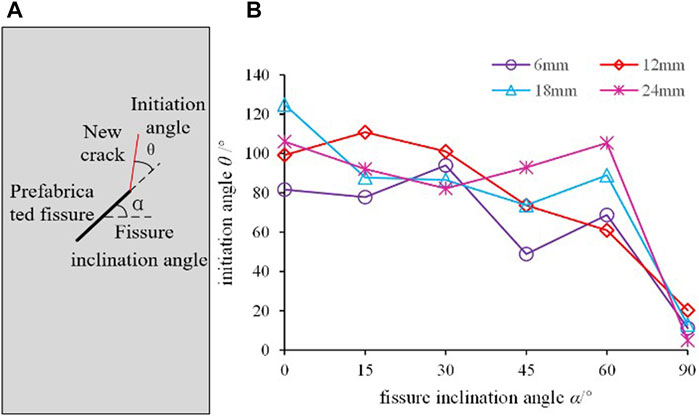
FIGURE 6. Relationship between the crack initiation angle and pre-existing fissure inclination angle. (A) Diagram of θ and α (B) θ vs. α
It can be observed from Figure 6 that, overall, the crack initiation angle gradually decreases with an increase in the pre-fabricated fissure inclination angle, which is similar to the influence of the fissure inclination angle on the pre-fabricated granite studied by Guo et al. (2019). As the inclination angle of the pre-fabricated fissure increases, the inclination angle of the originally initiated crack gradually approaches the direction of the pre-fabricated fissure. When the inclination angle of the fissure increased from 60° to 90°, the crack initiation angle abruptly decreased significantly, which is similar to the macroscopic integrity of the oblique shear, which is comparable to the oblique shear failure direction of the macroscopic intact sample. This variation was controlled by the variation in the particle displacement caused by the inclination angle and length of the pre-fabricated fissure, and the initial crack initiation direction may be one of the directions of the failure surface of the specimen.
3.1.2 Initiation and damage stress
Liu et al. (2017) predicted rock crack initiation stress (σci) and damage stress (σcd) based on Griffith’s strength theory. The specific method uses the lateral strain response method (LSR) (Nicksiar, M., and Martin, C. D., 2012), that is, to determine the maximum point and zero value point of the lateral strain difference through simple calculation to obtain the rock crack initiation stress and damage stress. In this study, the axial stress, axial strain curve, lateral strain curve, and volumetric strain relationship curve were obtained through the PFC model test, following the processing of data, the crack initiation stress and damage stress of rock samples with fissure lengths of 12 mm and 18 mm under different fissure inclination angle, as well as the variation law of their values with the fissure inclination angle, were obtained, as depicted in Figure 7. And under the condition of the same fissure inclination angle, α was set at 30° for analysis to obtain the variation law of fissure initiation stress and damage stress with an increase in the pre-fabricated fissure length, as depicted in Figure 8.
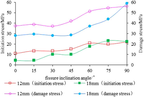
FIGURE 7. Relationship of crack initiation stress and damage stress with the fissure inclination angle.
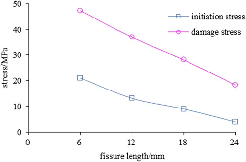
FIGURE 8. Relationship of crack initiation stress and damage stress with fissure length.
It can be observed from Figure 7 that the crack initiation stress and damage stress of the fissured rock sample increases with an increase in the fissure inclination angle, indicating that an increase in the fissure inclination angle strengthens the strength characteristics of the sample. In the process of increasing the inclination angle of the fissure, the mechanical properties of the specimens with fissures gradually approached the strength properties of the intact specimens. It can be observed from Figure 8 that the crack initiation stress and damage stress decrease with an increase in the pre-fabricated fissure length, indicating that with an increase in the fissure length, the effective area of the cross-sectional area of the sample with fissure will be reduced, and the strength variation characteristics of the sample are comparable to the principle of equivalent stress in damage mechanics.
It can be observed from Figure 7 that when α< 45°, the crack initiation stress and damage stress exhibit a relatively stable and slow increase with the change in the fissure inclination angle. When α≥45°, the crack initiation stress and damage stress exhibit an obvious increasing trend with the increase in fissure inclination angle. When comparing the test results of the 12 mm and 18 mm fissure lengths, it is evident that with an increase in the fissure length, the crack initiation stress and damage stress both decrease significantly, indicating that the increase in the pre-fabricated fissure length induces new cracks to initiate earlier under the same loading conditions.
3.2 Crack initiation characteristics
The PFC software was employed to simulate the initial stage of crack initiation to discuss the initiation of cracks near the prefabricated cracks. They found that the initiation of cracks was primarily affected by the inclination angle of the fissure. Therefore, a model sample with a pre-fabricated fissure length of 12 mm was used as an example to discuss the law of crack initiation and development near the pre-fabricated fissure. When the total number of cracks in the simulation test was less than 100, the crack initiation and development process of the sample was monitored using the PFC software, and the initial crack initiation and development of the sample under uniaxial compression were obtained, as shown in Figure 9.
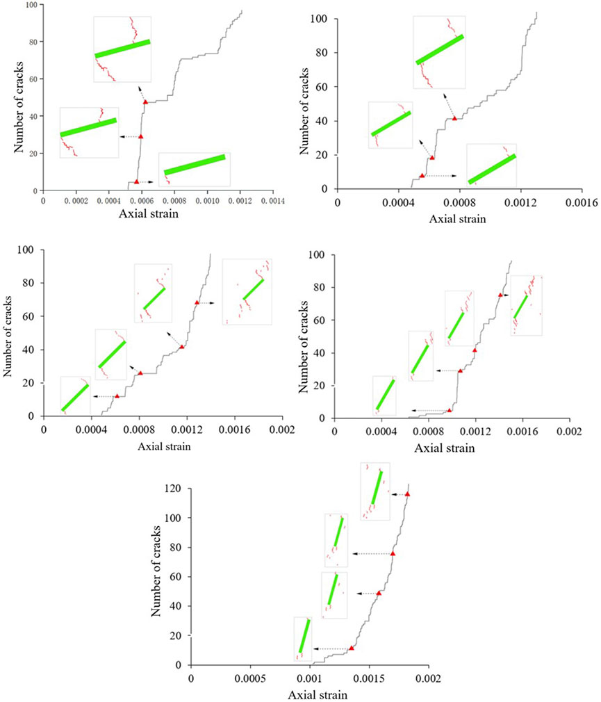
FIGURE 9. Initiation characteristics of cracks near prefabricated fissure(A)L=12 mm,α =15° (B) L=12 mm,α =30°(C) L=12 mm,α =45° (D)L=12 mm α =60°(E) L=12 mm,α =75°.
As shown in Figure 9, the cracks near the pre-fabricated fissure of the sample had a priority of initiation, indicating that obvious stress concentration regions were generated near the pre-fabricated fissure. It can be observed from Figures 9A,B that when α < 45°, the crack initiation does not begin from the tip of the pre-fabricated fissure, instead, it shifts to the center of the crack to a certain extent, and the initiated cracks all expand significantly. It can be observed from Figure 9C,E, when α≥45°, the crack initiation commenced from the tip of the pre-fabricated fissure and does not expand significantly, and many new cracks were generated near the pre-fabricated fissure. As the number of cracks (stress) increases, the development of later cracks was not limited to the vicinity of pre-fabricated cracks, indicating that pre-fabricated cracks were not the cause of new crack propagation, and new cracks tend to be “dispersion type” and filled with the entire surface of the specimen, which is also explained by the fissure inclination angle increase, and the strength characteristics of samples containing fissures are closer to those of intact samples. The 45° fissure inclination angle is a special angle, so that the projected length of the fissure in the direction perpendicular to the principal stress is equal to that in the direction parallel to the principal stress. From the perspective of fracture mechanics, the vertical stress acting on the fissure is close to the horizontal stress at this time, causing the cracks to expand in the vertical and horizontal directions with equal probability. This is also the reason why the crack initiation characteristics of the fissure change when the inclination angle of the fissure is 45°, and this phenomenon also occurs in the crack propagation characteristics hereinafter.
3.3 Crack propagation characteristics
The generation of microcracks in PFC is caused by the fracture of particle-particle contact. Tension cracks are formed when the contact between particles is damaged by tensile stress, and shear cracks are formed when they are damaged by shear stress. The relationship between the three dependent variables of axial stress, number of shear cracks, number of tensile cracks, and axial strain during the loading process of the specimen were simulated and discussed using PFC software, as well as the crack propagation law at three specific stress threshold points σci (initiation stress), σcd (damage stress) and σpeak (peak stress). Figure 10 illustrates the crack propagation process of the rock sample when L=12mm, α=0°, 30°, and 75°; Figures 11, 12 are α = 30°, L=18 mm, and α = 30°and 24 mm, respectively rock crack propagation process.
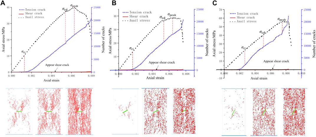
FIGURE 10. Crack propagation process of fissured samples with different inclination angles when L = 12 mm. (A) L 12 mm, α = 0 (B) L = 12 mm, α = 30 (C) L = 12 mm, α = 75.
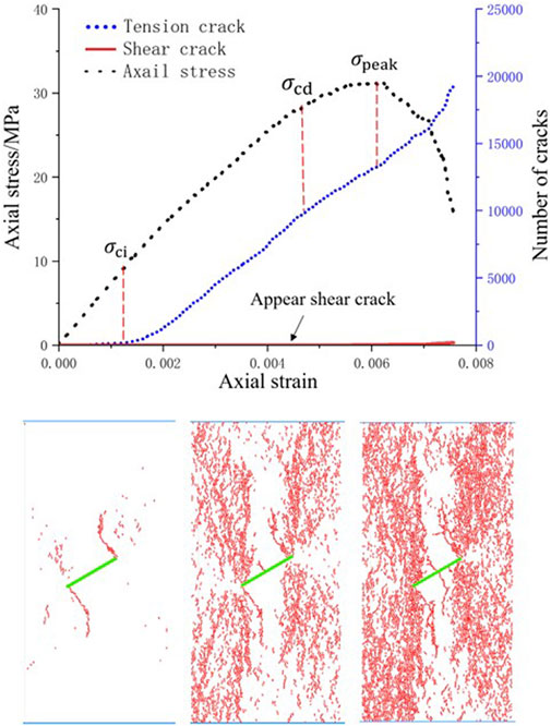
FIGURE 11. Micro-crack propagation process of a fissured specimen when L=18mm, α = 30°.
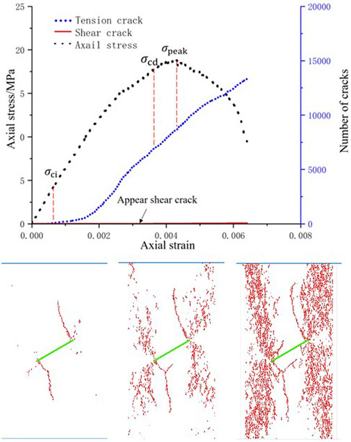
FIGURE 12. Micro-crack propagation process of fissured samples when L=24 mm, α = 30°.
It can be observed from Figure 10 that 1) there were no tension cracks in the sample at the initial loading stage. With an increase in the load, the tension crack was the primary crack before the crack initiation stress, whereas a shear crack occurred after the crack initiation stress, and the number of cracks was very small. In the steady crack growth stage, the tension crack increased steadily, and the rate of increase was significantly higher than that of the shear crack. 2) With an increase in the fissure inclination angle, the appearance time of the tension crack was hardly affected by the fissure inclination angle. When α≤30°, the appearance time of the shear crack was barely affected by the fissure inclination angle. When α>30°, the occurrence time of shear cracks is delayed, and the number of cracks increases steadily. 3) When the fissure penetrates the sample, the integrity of the sample is not completely lost, the rock still has a certain bearing capacity, and the sample has a shearing effect in the later stage of severe failure. Therefore, the failure mode reflects the tension-shear hybrid type damage, which is consistent with the experimental phenomenon. Simultaneously, in the uniaxial compression test of the sample with fissures, the number of meso-shear cracks was far less than that of tension cracks, and the physical test also showed that the macroscopic failure surface of the sample was caused by the expansion of the macroscopic cracks with tensile properties. Tensile failure was dominant, and the shear crack was only the result of the internal friction of the material. With an increase in load, the stress decreases rapidly, and the number of cracks is positively correlated with the fissure inclination angle.
It can be observed from Figure 10 that 1) when the pre-fabricated fissure inclination angle is small, the fissure inclination angles in Figures 10A,B are 0° and 30°, respectively. The crack distribution of the specimen after propagation had an obvious crack aggregation zone, and a dense crack aggregation zone appeared in the vicinity of the pre-fabricated fissure, indicating that the pre-fabricated fissure tip of the specimen was relatively broken, indicating that the pre-fabricated fissure tip will produce a stress concentration zone, which is also the priority area for crack initiation and propagation. 2) When the inclination angle of a fissure gradually increased from 0°, the aggregation zone of such cracks gradually weakened, which was the result of the change in the particle movement path caused by the change in the fissure inclination angle. The specific performance is as follows: when α≤ 30°, the crack distribution forms under the corresponding damage stress are similar, mainly manifested as the crack aggregation at the fissure tip; when α> 30°, as shown in Figure 10C, the cracks cover the entire surface of the sample, and the lower the degree of aggregation of cracks in this fissure inclination angle range, the higher the damage stress. 3) The more obvious the crack aggregation, the lower is the strength. With the increase of the fissure inclination angle, the stress at the three stages also increases gradually, indicating that the strength of the sample increases gradually when it expands in the direction of “dispersion”.
It can be observed from Figure 10B and Figures 11, 12 that under the same fissure inclination angle, with an increase in fissure length, the sample crack distribution presents obvious crack aggregation zones, the number of cracks decreases significantly, and there is a large number of blank regions without crack propagation. However, as the fissure length increased, the three specific stress threshold points σ ci, σcd, and σpeak decreased during the process of specimen expansion. From a microscopic perspective, it can be observed that with an increase in the fissure length, the crack initiation stress and crack propagation diagram corresponding to the damage stress time are similar, indicating that the crack propagation time decreases gradually, and the specimen is destroyed more rapidly. The crack propagation is primarily because the crack at the tip of the pre-fabricated fissure first expands to a certain extent to both ends, and then expands at the left and right ends of the entire sample away from the fissure, forming an “X-shaped” crack propagation mode. When comparing Figures 5A,B, it can be found that the crack growth and aggregation to a certain extent will form macroscopic cracks.
4 Conclusion
(1) Through a comparative analysis of the PFC2D numerical simulation of single-fissure rock and the deformation and failure of the indoor test, the simulation results were in good agreement with the test results, indicating that it is feasible to use PFC2D to simulate rock failure.
(2) In the process of crack propagation, the characteristic variables, such as peak stress, crack initiation angle, crack initiation stress, and damage stress vary law with the change of fissure inclination angle and fissure length. The outcome indicates that the peak stress increases with the increase of fissure inclination angle and decreases with the increase of fissure length. Moreover, the crack initiation angle decreases with the increase of fissure inclination angle. Additionally, the crack initiation stress increases with the increase of fissure inclination angle and decreases with the increase of fissure length. Furthermore, the damage stress increases with the increase of fissure inclination angle and decreases with the increase of fissure length.
(3) Failure characteristics of fractured rock: Failure mode of the rock sample is mainly controlled by fissure inclination angle and fragmentation degree is mainly controlled by fissure length. when α≤ 45°, the failure mode of rock samples was dominated by the development of wing cracks at both ends of the pre-fabricated fissure, and accompanied by a small number of cracks in the middle of the pre-fabricated fissure developed up and down to the end of the sample, which led to the fusion and penetration of cracks, resulting in sample damage. When α>45°, the main failure surface of the sample was formed by the main crack running through the pre-fabricated fissure, accompanied by the spalling of the side of the sample, the crack developed in the middle of the pre-fabricated fissure, and the formation of local far-field cracks. With an increase in the fissure inclination angle, the crack in the middle of the fissure gradually developed to both ends and subsequently disappeared.
(4) Crack initiation characteristics of fissured rock: The cracks near the pre-fabricated fissure is preferentially initiated, and the specific performance is as follows: when α <45°, the crack initiation position has a certain offset to the center of the prefabricated fissure, or starts from the tip of the prefabricated fissure, and the initiated crack has obvious propagation. When α ≥45°, the cracks are initiated from the tip of the pre-fabricated fissure. With an increase in the number of cracks (stress), the new cracks tended to be “dispersion-type” and began to cover the entire surface of the sample.
(5) Crack propagation law of fractured rock: In the process of crack propagation, new cracks were primarily generated by tension cracks, and shear cracks appear after the crack initiation stress; the number is very small. When the fissure length is constant, α ≤30°, and the crack distribution of the sample after the expansion has an obvious crack aggregation zone, and a dense crack aggregation zone all appears near the pre-fabricated fissure. When α>30°, the aggregation zone of cracks gradually weakens with the increase of fissure inclination angle, and the crack expands in the direction of “dispersion”. When the fissure inclination angle was constant, and with an increase in fissure length, the phenomenon of crack aggregation was more obvious. Overall, the number of cracks decreased, and the overall strength of the rock decreased.
Data availability statement
The original contributions presented in the study are included in the article/Supplementary Material, further inquiries can be directed to the corresponding author.
Author contributions
HY: Data curation, Writing- original draft preparation. TX: Supervision, funding acquisition HS: Writing- reviewing and editing. MH: Conceptualization, methodology, software.
Funding
This work was supported by the Hubei Provincial Science and Technology Plan Project Foundation of China (Grant No. 2020AC15), the Shanxi Provincial Key Laboratory of Concrete Structure Safety and Durability Open Fund of China (Grant No. SZ02105), and Open Fund for the State Key Laboratory of Geomechanics and Engineering of China (Grant No. Z020013).
Conflict of interest
The authors declare that the research was conducted in the absence of any commercial or financial relationships that could be construed as a potential conflict of interest.
Publisher’s note
All claims expressed in this article are solely those of the authors and do not necessarily represent those of their affiliated organizations, or those of the publisher, the editors and the reviewers. Any product that may be evaluated in this article, or claim that may be made by its manufacturer, is not guaranteed or endorsed by the publisher.
References
Bobet, A., and Einstein, H. H. (1998). Fracture coalescence in rock-type materials under uniaxial and biaxial compression. Int. J. Rock Mech. Min. Sci. 35 (7), 863–888. doi:10.1016/S0148-9062(98)00005-9
Chen, P. (2018). Loading rate effect analysis on rock particle flow model under uniaxial compression. Chin. J. Undergr. Space Eng. 14 (3), 635
Chen, Y., Cui, D., Bian, K., Li, Y., and Liang, W. (2020). Particle flow analysis on mechanical characteristics of composite rock samples containing coplanar double fractures. Saf. Environ. Eng. 27 (2), 140–148. doi:10.13578/j.cnki.issn.1671-1556.2020.02.019
Dyskin, A. V., Sahouryeh, E., Jewell, R. J., Joer, H., and Ustinov, K. B. (2003). Influence of shape and locations of initial 3-D cracks on their growth in uniaxial compression. Eng. Fract. Mech. 70 (15), 2115–2136. doi:10.1016/S0013-7944(02)00240-0
Fu, J., Zhu, W., Cao, G., Xue, W., and Zhou, K. (2013). Experimental study and numerical simulation of propagation and coalescence-process of a single three- dimensional flaw in rocks. J. China coal Soc. 38 (3), 411–417. doi:10.13225/j.cnki.jccs.2013.03.003
Gao, M., Li, T., Meng, L., Chen, G., Chen, C., and Liao, A. (2016). The method to identify characteristic stresses of rock in different stages during failure process. Chin. J. Rock Mech. Eng. 35 (S2), 3577–3588. doi:10.13722/j.cnki.jrme.2015.1645
Guo, Q., Wu, X., Cai, M., Ren, F., and Pan, J. (2019). Crack initiation mechanism of pre-existing cracked granite. J. China Coal Soc. 44 (S2), 476–483. doi:10.13225/j.cnki.jccs.2019.1212
Huang, Y., Yang, S., and Zeng, W. (2016). Experimental and numerical study on loading rate effects of rock-like material specimens containing two unparallel fissures. J. Cent. South Univ. 23 (6), 1474–1485. doi:10.1007/s11771-016-3200-3
Li, F., and Li, X. (2013). Micro-numerical simulation on mechanism of fracture coalescence between two pre-existing flaws arranged in echelon. J. Shenzhen Univ. Sci. Eng. 30 (2), 190–194. doi:10.3724/sp.j.1249.2013.02190
Li, H., and Wong, L. N. Y. (2012). Influence of flaw inclination angle and loading condition on crack initiation and propagation. Int. J. Solids Struct. 49 (18), 2482–2499. doi:10.1016/j.ijsolstr.2012.05.012
Li, X., Niu, Z., Yao, Q., Wang, W., and Yu, L. (2020). Particle flow analysis of crack propagation characteristics of hole-type trident cracks sandstone. J. China Coal Soc. 45 (11), 3735–3747. doi:10.13225/j.cnki.jccs.2019.1216
Liu, Q., Wei, L., Liu, X., Liu, J., and Pan, Y. (2016). A revised empirical method for predicting crack initiation based on Griffith strength criterion. Chin. J. Rock Mech. Eng. 36 (7), 1561–1569. doi:10.13722/j.cnki.jrme.2016.0398
Lou, C., Zhao, Q., Zhang, C., and Lu, X. (2019). Protection effect of geotextile mattress with sloping plate on scour below underwater pipeline. Yangtze River 50 (01), 158–162+183. doi:10.16232/j.cnki.1001-4179.2019.01.029
Mi, W. (2020). Numerical simulation of biaxial compression crack growth of specimen with single and double internal cracks under different hydraulic fracturing factors. Chin. J. Undergr. Space Eng. 16 (2), 516
Nicksiar, M., and Martin, C. D. (2012). Evaluation of methods for determining crack initiation in compression tests on low-porosity rocks. Rock Mech. Rock Eng. 45 (4), 607–617. doi:10.1007/s00603-012-0221-6
Niu, J., Huang, K., Yao, C., and Yang, J. (2016). Numerical simulation of failure mechanism of fractured rock with different apertures under uniaxial compression. Yangtze River 47 (22), 87–91. doi:10.16232/j.cnki.1001-4179.2016.22.019
Pan, X. (2017). Numerical simulation of the failure characteristics of rocks containing coplanar nonpersistent fissures under uniaxial compression. Chin. J. Undergr. Space Eng. 13 (4), 892
Sarfarazi, V., Haeri, H., and Bagheri, K. (2018). Numerical simulation of shear mechanism of concrete specimens containing two coplanar flaws under biaxial loading. Smart Struct. Syst. 22 (4), 459–468. doi:10.12989/sss.2018.22.4.459
Shu, Y., Wu, J., Yue, L., Liu, J., and Le, H. (2016). Numerical simulation of mechanical behavior of single fractured rock mass under direct shear. J. PLA Univ. Sci. Technol. Sci. Ed. 17 (5), 424
Tian, W., Yang, S., and Huang, Y. (2017). PFC2Dsimulation on crack evolution behavior of brittle sandstone containing two coplanar fissures under different confining pressures. J. Min. Saf. Eng. 34 (6), 1207–1215. doi:10.13545/j.cnki.jmse.2017.06.026
Wang, Q., Wang, J., Ye, Y., Wang, W., Huang, C., Hu, N., et al. (2020). Development and preliminary verification of the evaluation system for clinical practice guidelines in China. Chronic Dis. Transl. Med. 49 (2), 134–139. doi:10.1016/j.cdtm.2019.08.007
Wang, Y., Zhang, H., Lin, H., Zhao, Y., and Liu, Y. (2020). Fracture behaviour of central-flawed rock plate under uniaxial compression. Theor. Appl. Fract. Mech. 106, 102503. doi:10.1016/j.tafmec.2020.102503
Wang, Y., Zhou, X., Wang, Y., and Shou, Y. (2018). A 3-D conjugated bond-pair-based peridynamic formulation for initiation and propagation of cracks in brittle solids. Int. J. Solids Struct. 134, 89–115. doi:10.1016/j.ijsolstr.2017.10.022
Wang, Z., Zhao, W., and Pan, K. (2020). Analysis of fracture evolution characteristics of coplanar double fracture rock under uniaxial compression. Geotech. Geol. Eng. (Dordr). 38 (1), 343–352. doi:10.1007/s10706-019-01022-9
Wei, C., Zhang, B., Zhu, W., Wang, S., Li, J., Lin, C., et al. (2021). Fracture propagation of rock like material with a fluid-infiltrated pre-existing flaw under uniaxial compression. Rock Mech. Rock Eng. 54 (2), 875–891. doi:10.1007/s00603-020-02256-3
Xi, X., Wu, X., Guo, Q., and Cai, M. (2020). Experimental investigation and numerical simulation on the crack initiation and propagation of rock with pre-existing cracks. Ieee Access 8, 129636–129644. doi:10.1109/ACCESS.2020.3009230
Xiao, T., Li, X., and Jia, S. (2012). Triaxial test research and mechanical analysis based on structure surface effect of deep rock mass with single fissure. Chin. J. Rock Mech. Eng. 31 (8), 1666–1673. doi:10.3969/j.issn.1000-6915.2012.08.021
Zeng, Z., He, G., Dai, B., and Chen, K. (2021). Analysis of mechanical properties and crack propagation of rocks with double holes type double fissures. Nonferrous Met. Eng. 11 (5), 87–95. doi:10.3969/j.issn.2095-1744.2021.05.014
Zhang, L., Jing, H., Ding, S., and Yang, L. (2017). Discrete element study on crack coalescence behavior of sandstone with two parallel fissures. Coal Technol. 36 (4), 326–329. doi:10.13301/j.cnki.ct.2017.04.120
Zhang, X., and Wong, L. N. Y. (2012). Cracking processes in rock-like material containing a single flaw under uniaxial compression: A numerical study based on parallel bonded-particle model approach. Rock Mech. Rock Eng. 45 (5), 711–737. doi:10.1007/s00603-011-0176-z
Zhang, Y., Wang, K., Yao, X., Liang, X., Liang, P., and Liu, X. (2019). Simulation experiment study on the effect of fracture geometry on rock strength. China Min. Mag. 28 (08), 141
Zhao, Y., Liu, Q., Zhang, C., Liao, J., Lin, H., and Wang, Y. (2021). Coupled seepage-damage effect in fractured rock masses: Model development and a case study. Int. J. Rock Mech. Min. Sci. 144, 104822. doi:10.1016/j.ijrmms.2021.104822
Zhao, Y., Wang, Y., Wang, W., Tang, L., Liu, Q., and Cheng, G. (2019). Modeling of rheological fracture behavior of rock cracks subjected to hydraulic pressure and far field stresses. Theor. Appl. Fract. Mech. 101, 59–66. doi:10.1016/j.tafmec.2019.01.026
Zhao, Y., Zhang, L., Liao, J., Wang, W., Liu, Q., and Tang, L. (2020). Experimental study of fracture toughness and subcritical crack growth of three rocks under different environments. Int. J. Geomech. 20 (8), 04020128. doi:10.1061/(ASCE)GM.1943-5622.0001779
Zhou, X., Cheng, H., and Feng, Y. (2014). An experimental study of crack coalescence behaviour in rock-like materials containing multiple flaws under uniaxial compression. Rock Mech. Rock Eng. 47 (6), 1961–1986. doi:10.1007/s00603-013-0511-7
Zhou, X., Lian, Y., Wong, L. N. Y., and Berto, F. (2018). Understanding the fracture behavior of brittle and ductile multi-flawed rocks by uniaxial loading by digital image correlation. Eng. Fract. Mech. 199, 438–460. doi:10.1016/j.engfracmech.2018.06.007
Zhou, X., Wang, Y., Zhang, J., and Liu, F. (2019a). Fracturing behavior study of three-flawed specimens by uniaxial compression and 3D digital image correlation: Sensitivity to brittleness. Rock Mech. Rock Eng. 52 (3), 691–718. doi:10.1007/s00603-018-1600-4
Zhou, X., and Zhang, J. (2021). Damage progression and acoustic emission in brittle failure of granite and sandstone. Int. J. Rock Mech. Min. Sci. 143, 104789. doi:10.1016/j.ijrmms.2021.104789
Keywords: pre-fabricated single fissure, rock-like materials, PFC2D, failure mode, cracks initiation, cracks propagation
Citation: Yuan H, Xiao T, She H and Huang M (2023) Crack propagation law of rock with single fissure based on PFC2D. Front. Earth Sci. 10:977054. doi: 10.3389/feart.2022.977054
Received: 28 June 2022; Accepted: 24 October 2022;
Published: 11 January 2023.
Edited by:
Fanyu Zhang, Lanzhou University, ChinaReviewed by:
Xiaoping Zhou, Chongqing University, ChinaYanlin Zhao, Hunan University of Science and Technology, China
Wei Chen, Hunan University of Science and Technology, China
Ping Wang, Lanzhou Earthquake Research Institute, China Earthquake Administration, China
Copyright © 2023 Yuan, Xiao, She and Huang. This is an open-access article distributed under the terms of the Creative Commons Attribution License (CC BY). The use, distribution or reproduction in other forums is permitted, provided the original author(s) and the copyright owner(s) are credited and that the original publication in this journal is cited, in accordance with accepted academic practice. No use, distribution or reproduction is permitted which does not comply with these terms.
*Correspondence: Taoli Xiao, MjAwNTM2QHlhbmd0emV1LmVkdS5jbg==; Haicheng She, c2hlaGFpY2hlbmdAMTI2LmNvbQ==