 Xia Liu
 Tiejun Tao
 Xingchao Tian
- Guizhou University, College of Civil Engineering, Guiyang, Guizhou, China
The traditional tunnel-drilling and blasting parameter design is based on the small-section roadway and involves many boreholes and conditions that require slow operation progress and thus cannot meet the rapid operation requirements of a large-span tunnel. Taking the Baizhushan Tunnel as the engineering background, this article put forward a theoretical basis for a hole-reducing layout method for large-section tunnel blasting. These parameters of the rock statics and dynamics were obtained through core-drilling sampling in the field and the development of static and dynamic tests. LS-DYNA software was used to establish the numerical model of large-span tunnel blasting. The method was verified through three aspects, namely, cavity effect, effective stress, and surrounding rock damage and was implemented in the field application. The results showed the following: the scheme for reducing-hole numbers used 26 fewer blast holes per cycle footage and saved 0.7 h of drilling time; the average effective stress of the retained rock was 0.6 times that of the original blasting scheme, which reduced the damage to the remaining rock; the maximum over-excavation thickness control was within 50 cm, which reduced over-break; in the field test, the utilization rate of cutting holes was 81.9%, the utilization rate of other blasting holes was 91.2%, the unit consumption of explosives was 0.72 kg/m3, the average over-excavation thickness control was within 20 cm, and the smooth blasting effect was superior.
1 Introduction
With the implementation of national strategies such as “Western Development,” “Poverty Alleviation,” and “Traffic Power,” highway construction is developing rapidly. In the highway construction of complex and dangerous mountainous areas, the factors of topography and geology determine the need for large-scale tunnel construction (Zhang and Zhang, 2012). The drill-blasting method is the main method used for tunnel construction. However, due to the tunnel sections being too wide and the geology of the karst mountain area being too complicated, the traditional tunnel-blasting parameter design and construction technology can no longer meet the requirements of safe and efficient tunnel construction in complex mountain areas (Yang et al., 2010; Ma, 2022). At present, the tunnel in the eastern section of Shenyang, China, can be considered the tunnel with the largest sections. The width of the standard subsection is 27.1 m, and the width of the widening sections is 42.6 m. When constructing a super-large cross-section rock tunnel by the drill-blasting method, the large number of drilling holes and the slow construction progress seriously affect the construction efficiency of the whole project. Therefore, there is an urgent need for a new method suitable for the blasting construction of the large-span tunnel.
Ji et al. (2021) established the blasting damage model by combining the tensile damage model and the Drucker–Prager yield condition. Based on the definition of damage threshold Drc and using LS-DYNA software to simulate the full-section blasting damage process many times, it was determined that the maximum damage depth and the maximum PPV appeared in the inner bottom of the tunnel, and the critical PPV was therefore proposed as a safety criterion for rock damage. Ma et al. (2020), in order to improve the construction efficiency of large cross-section tunnels, reduce the production cost, and simplify the construction process, carried out a series of detonation tests on tunnel excavation faces to determine the critical distance of emulsion explosive under the constraint of blast holes and proposed a smooth blasting technology without the detonating cord. Ling et al. (2020) proposed inverted T-cut blasting for a large-span section tunnel. Combining numerical simulation and field tests, and comparing and analyzing the blasting effects of single-wedge-cutting blasting and inverted T-cut blasting in an extra-large cross-section tunnel, the average blasting hole utilization rate of this blasting method was 90.2%, the unit explosive consumption was 0.75 kg/m3, and the smooth blasting effect was superior. Pan et al. (2022) determined the parameters of the periphery-hole through the eccentric charge structure, studied the blasting effects of different charge structures based on Riedel–Hiermaier–Thoma (RHT), and drew the conclusion that the eccentric charge structure had obvious eccentric pressure. Based on the eccentric charge structure, the smooth blasting parameters were optimized, and the under-excavation phenomenon was well-controlled. Meng et al. (2022) studied the influence of blasting delay time and spacing of post-blasting holes on crack formation in sequentially controlled pre-splitting blasting and optimized the blasting parameters. Shan et al. (2022), based on the Heelan short column charge theory and introducing the equivalent radius, obtained the attenuation equation of peak blasting vibration velocity.
At present, research on large-span section tunnel blasting is mainly focused on blasting vibration control, charge structure, and blast hole spacing. Many challenging problems in tunnel blast sites have been solved, and blasting effects have been optimized. However, research on the new method of arranging hole nets in large-span section tunnel blasting has not been reported yet. Therefore, based on the Baizhushan Tunnel of Leishan–Rongjiang Expressway in Guizhou Province, this article put forward a new theory and method for reducing hole numbers in large-span section tunnel blasting that completely change the design concept of “more holes and less charge” in traditional tunnel blasting. Through field sampling and by conducting uniaxial compression tests, triaxial compression tests, Brazilian splitting tests, and split Hopkinson pressure bar (abbreviated as SHBP) tests, standard rock samples and the static and dynamic parameters of the surrounding rock were obtained. Using LS-DYNA software, the numerical model of large-span section tunnel blasting was established, and the method was verified through three aspects of cutting cavity, effective stress, and surrounding rock damage and was implemented to the field application. The research results provided a new hole net layout method for large-span section tunnel blasting, reducing the number of boreholes and improving the operation efficiency.
2 Materials and methods
2.1 Engineering background
The Baizhushan Tunnel is a separate extra-long tunnel. The left length of the tunnel is 4,358 m, and the maximum buried depth is 318 m. The right length of the tunnel is 4,404 m, and the maximum buried depth is 323 m. The distance between the left and right lines of the tunnel is 16–41 m. The tunnel is a Renzipo tunnel. The longitudinal slopes of the left and right tunnels are 2.0% and −1.35%, respectively. The ZK20-770∼ZK21-215 section was selected as the research section. The roof depth of this section is 54.6 ∼ 195.48 m. The surrounding rock is medium-weathered thin-to-medium-thick-layered tuffaceous slate, and the joint fissure is developed. The rock mass
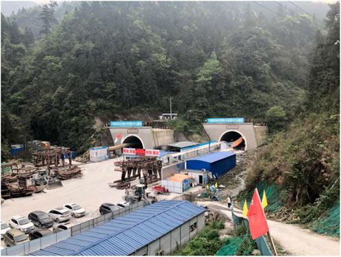
FIGURE 1. Baizhushan Tunnel.
There are two main problems in the construction process of the Baizhushan Tunnel. First, the traditional tunnel blasting method caused a large number of holes. The layout of traditional blast holes is estimated according to the tunnel section area and rock hardness coefficient:
In this article, the cross-section area of the upper bench of the tunnel in the test section is
Second, according to the traditional blasting scheme, the over-excavation of the Baizhushan Tunnel is significant, and five field blasting tests have been carried out. The over-excavation and under-excavation data are shown in Table 1, with the maximum over-excavation being 60.0 cm and the average over-excavation thickness being 36.70 cm. The code stipulates that the maximum allowable value of over-excavation (National standard of the People 's Republic of China GB50299, 1999) is 15 cm, and the traditional design scheme is significantly over-excavated, which seriously increases the construction cost.
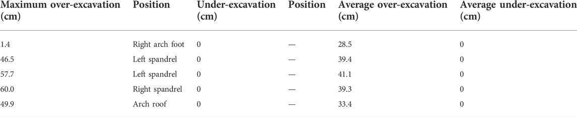
TABLE 1. Over-excavation and under-excavation.
2.2 Determination of mechanical parameters of slate
In order to obtain the static and dynamic parameters of surrounding rock in this section, drilling core sampling obtained the standard slate samples. As shown in Figure 2, the uniaxial compression test, triaxial compression test, and Brazilian splitting test were carried out on a TAJW-2000 rock triaxial testing machine controlled using a microcomputer. Six cylindrical rock samples with a diameter of 50 mm and height of 100 mm were prepared for the uniaxial compression test and triaxial compression test; three cylindrical rock samples with a diameter of 50 mm and height of 50 mm were prepared for the Brazilian splitting test; and three cylindrical rock samples with a diameter of 50 mm and height of 25 mm were prepared for the SHPB test, as shown in Figure 3. The sample size was measured using a Vernier caliper and weighed using the electronic balance. The average density of the sample was 2,721 kg/m3.
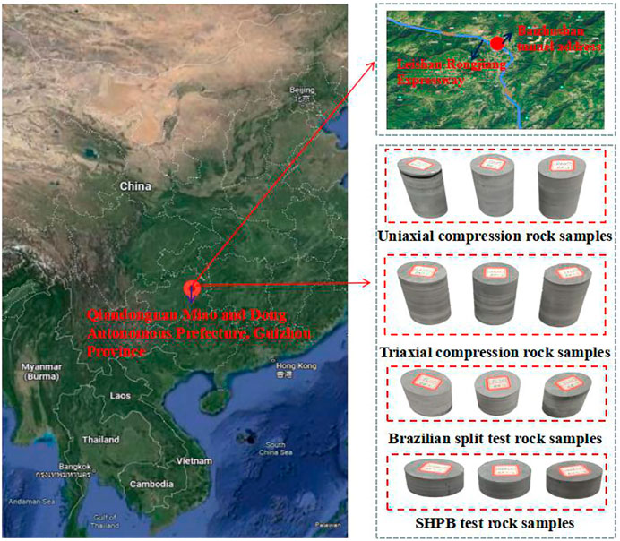
FIGURE 2. Slate rock test samples.
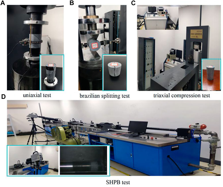
FIGURE 3. Mechanical test of slate.
The purpose of the uniaxial compression test was to obtain the uniaxial compressive strength, elastic modulus, and Poisson’s ratio of the rock samples. When carrying out the uniaxial compression test, the preloading of 0.2 KN was applied first; after the instrument was stabilized, it was converted to displacement loading. The loading rate was 0.12 mm/min, and the uniaxial compression process is shown in Figure 3A. According to
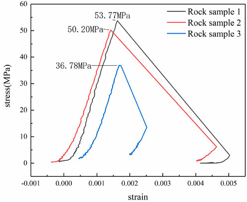
FIGURE 4. Stress–strain curve of uniaxial compression.
The main purpose of the triaxial compression test was to obtain the strength parameters B and N of the HJC constitutive model. Three groups of tests were carried out, and the confining pressures of 5, 10, and 15 MPa were applied to the samples, respectively. The test process is shown in Figure 3C. According to
The Brazilian splitting test was carried out to obtain the tensile strength of rock samples. The linear load was applied in the diameter direction of the cylindrical specimen, and the loading rate was 0.15 mm/min until the rock sample was destroyed. The Brazilian splitting test process is shown in Figure 3B. The tensile strength of the rock sample was determined as
The purpose of the SHPB test was to calculate the strain rate influence coefficient C of the HJC constitutive model. The SHPB test was carried out through the separate Hopkinson compression bar test system ALT100 developed by Archimedes Industrial Technology Co., Ltd. The experimental process is shown in Figure 3D. Based on the impact experimental data of slate processed by the two-wave method and three-wave method, it was concluded that, when the impact pressures were 0.1, 0.2, and 0.3 MPa, the average peak stresses of rock failure were 89.5, 95.2, and 101.8 MPa, respectively, and the corresponding average strain rates were 103.50, 180.21, and 201.42 s. It was found that the greater the impact load, the greater the peak stress of the rock. Since the strain sensitivity under loading had little effect on the rock dynamic tensile strength, it was considered that the rock uniaxial tensile strength and dynamic tensile strength were the same. The mechanical parameters of slate are shown in Table 2.
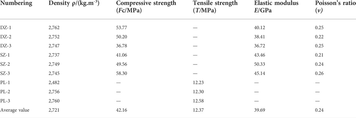
TABLE 2. Mechanical parameters of slate.
3 Theoretical method of blasting reduced-hole layout for large-section tunnels
The blast hole layout of traditional tunnel blasting was developed for the small cross-section roadway, with a large number of blast holes and more blast holes in the center of the face, and it is difficult for on-site workers to complete such a dense blast hole layout. In the actual project, to improve tunnel construction efficiency and reduce construction cost, the method of applying less drilling and more charge is adopted to improve the blasting excavation speed. However, this leads to damage to retained rock mass, significant over-excavation, and high consumption of the initial concrete. Through combined theoretical analysis, numerical simulation, and field tests, this article put forward a theoretical method for the design of wide hole spacing in large cross-section tunnels, pushing the wedge-shaped cutting hole outward to the maximum extent to liberate the central face of the tunnel. According to the criteria for determining the damage to retained rock mass, the optimal cutting hole angle and the optimal layout position were determined. The design concepts of wide hole spacing and small row spacing were introduced to break the bottleneck of the traditional blast hole net layout. This controls the tunnel profile and damage to retained rock mass more effectively while reducing the amount of drilling and associated drilling costs and improving the tunneling efficiency of large cross-section tunnel blasting.
This article, based on the Baizhushan Tunnel of Leirong Expressway, put forward a new method of reducing hole numbers with wide hole spacing and small row spacing in a large-span section tunnel, which “pushed out” the position of the wedge-shaped cutting hole to a safe distance d from the design outline of the tunnel. Under this condition, the wedge-cut blasting will not cause damage to the reserved rock mass outside the tunnel outline. At the same time, according to the mechanical mechanism and rock-breaking mechanism of wedge-cut blasting, the optimal angle β (the angle between the free surface and the direction along the length of the wedge-cutting hole) is determined, which enables the rock mass to be fully broken under the action of reflected tensile waves, in order to ensure that the wedge-cutting blasting can better provide two-way liberation of the heading face while ensuring that the retained rock mass separates from the central rock mass of the heading face. Even if the subsequent blasting uses increased explosive quantity, it will not cause damage to the retained rock mass. The blast hole schematic diagram of the original blasting scheme is shown in Figure 5A, and the blast hole schematic diagram of the reduced-hole scheme is shown in Figure 5B.
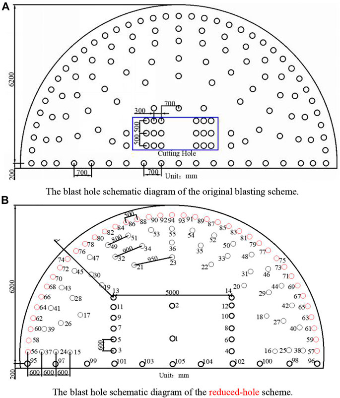
FIGURE 5. Schematic diagram of the blast hole layout. (A) Blast hole schematic diagram of the original blasting scheme. (B) Blast hole schematic diagram of the reduced-hole scheme.
The core objective of this method was to determine the safe distance d from the No. 13 and No. 14 cutting holes to the tunnel contour line, and the optimal angle
The first step was to determine the safe distance d from the No. 13 and No. 14 cutting holes to the tunnel outline. According to the detonation wave theory, the initial shock-wave pressure of the cylindrical charge acting on the rock using the uncoupled charge is P (Yuan, 2014).
In the formula,
According to the attenuation law of stress waves, the peak of radial pressure at a specific distance
In this equation,
As a medium with high compressive strength and low tensile strength, rock is most prone to tensile failure in the process of blasting, so the tensile strength of rock is taken as the failure standard, and when
The second step was to determine the optimal angle β of the wedge-cutting holes and establish the numerical model of wedge-cutting blasting. As shown in Figure 6, the rock breaking mechanism of cutting blasting was analyzed (Wang, 2016; He, 2017a; Wang, 2020; Yang et al., 2022). The shear resistance of the face
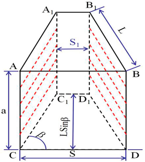
FIGURE 6. Rock-breaking mechanism of cut blasting.
In this equation,
Therefore, the total shear resistance of the free surface is
The tensile resistance of the face
In this equation,
According to the isentropic expansion, the resultant force
In this equation,
The tensile strength of rock is small, and the shear stress of plane
To enable the rock in the cutting cavity to be thrown out and the rock in the groove cavity to reach limit equilibrium under the static action, the following formula must be met:
The safe distance
4 Numerical simulation
4.1 Determination of materials
4.1.1 Determination of rock materials
The Johnson–Holmquist concrete (HJC) takes (Chen et al., 2016; Luo et al., 2021) the influence of strain rate and cumulative damage, which describes the fracture behavior of brittle materials under explosive impact load. The HJC constitutive model includes basic mechanical parameters, strength parameters, damage parameters, and pressure parameters.
The basic mechanical parameters
According to the 0.10 MPa impact pressure test results, starting from the characteristic tensile strength
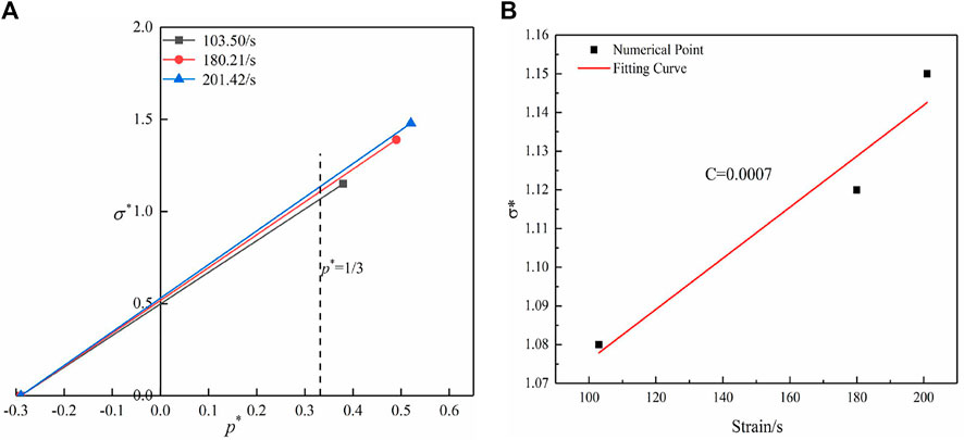
FIGURE 7. Strain rate influence factor C. (A) Relationship between characteristic equivalent stress and hydrostatic pressure under different strain rates. (B) Relationship between characteristic equivalent stress and strain rate.
According to the triaxial compression test data, the cohesion
The pressure parameters
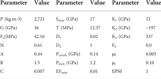
TABLE 3. Parameters of the HJC model for slate.
4.1.2 Determination of explosive materials
Field use of 2# emulsion explosive, adopting MAT_HIGH_EXPLOSIVE_BURN material combined with the JWL equation of state, describes the relationship between detonation pressure and specific volume in the process of detonation (Cheng et al., 2021):
where
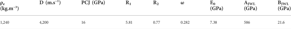
TABLE 4. Parameters for the explosive material and JWL EOS.
4.2 Establishment of the model
The parameters of field use of 2# emulsion explosive were as follows: density
There were 131 blasting holes in the upper steps of the original blasting scheme, including 18 cutting holes, 59 auxiliary holes, 35 peripheral holes, and 19 bottom holes. The scheme was subjected to three-stage compound wedge cutting. The first-stage cutting was inclined to the tunnel center angle of 69°, and the blast hole length was 1.5 m. The second-stage cutting was 72°, and the blast hole length was 2.3 m. The third-stage cutting was 73°, and the blast hole length was 3.8 m. The other blast hole lengths were 3.5 m. The blasting parameters are shown in Table 5. There were 105 blasting holes in the upper steps of the reduced-hole layout scheme, including 12 cutting holes of 4.2 m blasting hole length, 41 auxiliary holes, 39 periphery holes, and 11 bottom holes. The blast hole lengths were 3.5 m. Two blast holes with low charge were arranged in the center of the heading face to decompose the large chunks of rock (these are collectively referred to as the unloading hole), and the blasting hole length was 3 m. The blasting parameters are shown in Table 6.
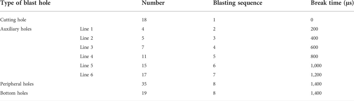
TABLE 5. Blasting parameters of the original scheme.
TABLE 6. Blasting parameters of the reduced-hole layout scheme.
ANSYS/LS-DYNA software can better simulate complex structure calculations, especially for solving nonlinear problems, such as high-speed collision and explosion shock. LS-DYNA software was used to establish the blasting model of the reduced-hole layout with the size of 20 m × 20 m × 3.5 m (X × Y × Z) and the original blasting model. The schematic diagram of the two models is shown in Figure 8. Figure 8A is a schematic diagram of the original blasting scheme model. Figure 8B is a schematic diagram of the reduced-hole layout blasting scheme model. The charge structure adopted was an uncoupled charge, the cartridge diameter was 32 mm, and the blast hole diameter was 42 mm. In a study, for conducting a more realistic simulation of on-site blasting and rock selection using HJC material (Banadaki, 2010; Xie et al., 2017; Dong, 2019; Li et al., 2022), the authors defined the keyword initial-detonation to delay initiation and added the keyword mat_add_erosion as the erosion failure criterion to control the failure of the unit. The minimum tensile stress was defined as the failure criterion of the surrounding rock. The finite element mesh was the SOLID164 element, which was divided into about 800,000 grids. The model adopted a cm∼g∼μs unit system. In order to avoid the influence of the reflection wave caused by the artificial boundary on the calculation results, the heading face was set at the free boundary, and the other five surfaces were set at the non-reflection boundary. The hole-bottom initiation blasting method was adopted, and the total simulation initiation time was 4,000 µs. The calculation used the fluid–solid coupling algorithm.
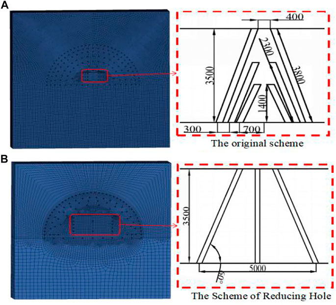
FIGURE 8. Schematic diagram of the two models.
4.3 Result analysis
4.3.1 Analysis of the effect of the blasting cavity
There are a large number of blast holes in the original blasting scheme on the site, and the rock mass in the excavation section is bound to be broken. Therefore, this article did not describe the effect of the original blasting scheme cutting cavity. However, the blasting scheme of the reduced-hole layout pushed the wedge-cutting hole outward to the maximum extent and greatly reduced the number of blasting holes in the central part of the tunnel face. In order to observe the formation of the tunnel cavity after the reduction in the number of blasting holes, the authors extracted a cloud chart of cutting cavity formation at a different timepoint in the process of reduced-hole layout blasting, as shown in Figure 9. The effective stress of the tunnel face was lower after the initiation of the cutting hole. After the initiation of the auxiliary hole, the effective stress began to superimpose increased effective stress around the central part of the heading face and the cutting hole. After the initiation of the peripheral hole and the bottom hole, the superposition effect was more obvious, the effective stress in the central part of the heading face continued to increase, and cumulative damage occurred in the rock mass at the position of the excavation section. When t = 2000 µs, the stress wave produced by the peripheral hole propagated through the whole excavation section, and because the distance between the auxiliary hole and the peripheral hole was small, the stress-superposition effect was more obvious, the effective stress around the profile of the peripheral hole was higher, and the surrounding rock mass was seriously damaged. Under this blasting scheme, when the safe distance from the No. 13 and No. 14 cutting holes to the tunnel profile was set to 2.81 m and the angle of the cutting hole was set to 60°, a better cutting cavity and tunnel profile were formed. This shows that the implementation of the blasting scheme of the hole-reduction layout can ensure the quality of tunnel profile formation.
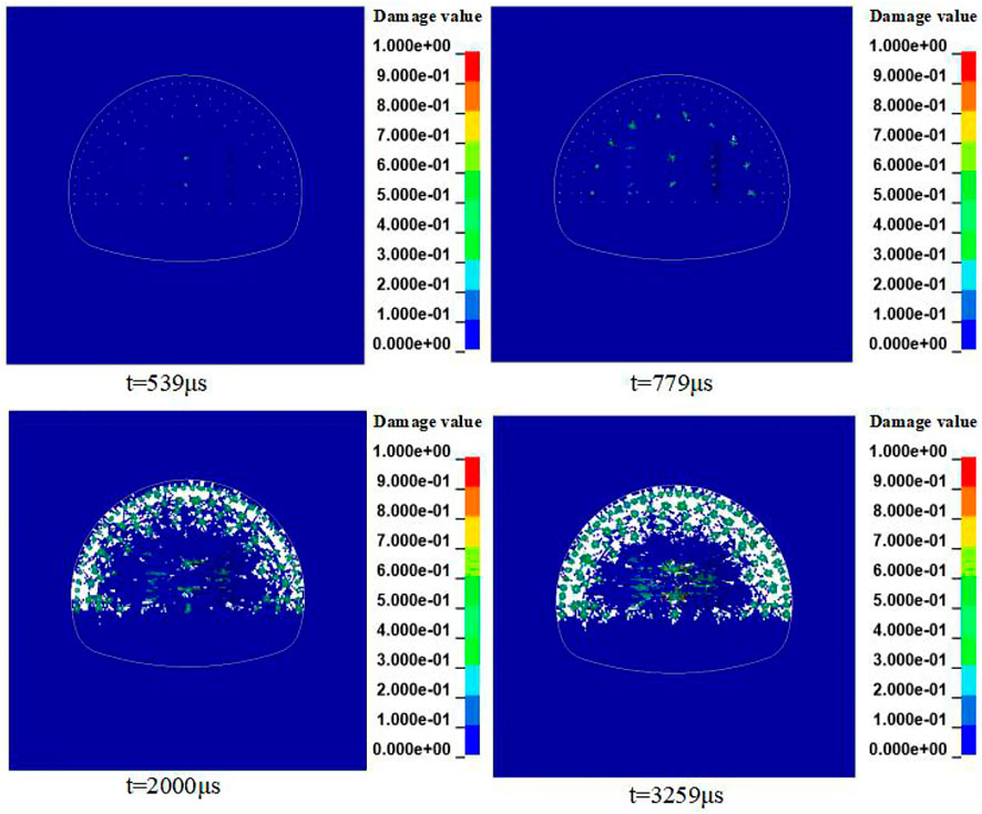
FIGURE 9. Formation process of a blasting cavity.
As a medium with high compressive strength and low tensile strength, the failure of rock is usually tensile in nature. In order to more accurately understand the “outward push” of the wedge-shaped cutting hole in the center of the heading face, and the blasting effect after reducing the number of blast holes, the question of whether such an approach can meet the requirement of 3.3 m of cyclic footage needed to be answered. Therefore, the authors extracted the peak tensile stress of the element at 0.5, 1, 2.8, 3.3, and 3.5 m from the heading face between the left cutting hole and the unloading hole and compared the results with the tensile strength of the slate in Table 2, as shown in Figure 10. It can be seen that the peak of tensile stress under 3.3 m from the heading face was greater than the tensile strength of rock 12.37 MPa, indicating that it met the requirement of cyclic footage of 3.3 m, and the peak tensile stress at 3.5 m from the heading face was less than the tensile strength of rock. This showed that the blasting scheme meets the footage requirement of 3.3 m, can effectively break the surrounding rock, and will not damage the newborn heading face.
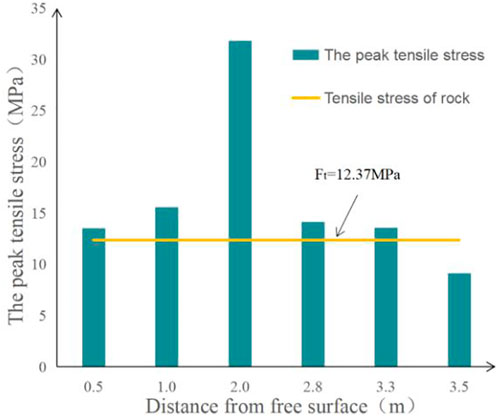
FIGURE 10. Tensile stress during blasting at different positions.
4.3.2 Effective stress analysis
In order to analyze the effective stress of the two layout schemes in the blasting process, the authors extracted the effective stress data of the arch foot, hance, spandrel, and arch roof elements of the two models (the locations of the elements are shown in Figure 11).
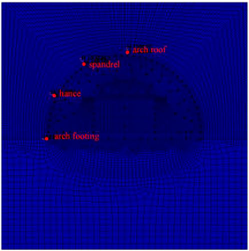
FIGURE 11. Locations of the elements.
As can be seen from Figure 12, the effective stresses of the two blasting schemes were different in the arch foot, hance, spandrel, and arch roof, but the changing trend of the effective stress in the same position was the same. For both schemes, the peak of the effective stress at the arch foot was the highest. The effective stress at the spandrel was the minimum.

FIGURE 12. Effective stress.
The first effective stress peak of the hole-reduction scheme appeared earlier than that of the original blasting scheme. Before t = 1,500 µs, the effective stress of the hole-reduction scheme was higher than that of the original blasting scheme, because the cutting hole, auxiliary hole, and peripheral hole of the hole-reduction scheme were all detonated, and the superposition of reflected waves increased the effective stress at this time. When all the holes in the original blasting scheme were detonated, the effective stress was greater than that of the reduced-hole blasting scheme because the number of holes in the original blasting scheme was greater. In the original blasting scheme, the effective stress peaks of the arch foot, hance, spandrel, and arch roof were 97.86, 65.01, 63.78, and 67.55 MPa, respectively. The effective stress peaks of the arch foot, hance, spandrel, and arch roof of the blasting scheme with the reduced-hole layout were 67.50, 36.33, 33.01, and 35.41 MPa, respectively. The average peak of effective stress of the retained rock mass unit in the blasting scheme with a reduced-hole layout was 0.6 times that of the original blasting scheme. By comparing the effective stress of the two blasting schemes, it was found that the effective stress of the original blasting scheme was higher in the retained rock mass, which caused excessive damage to the retained rock mass. However, the hole-reduction blasting scheme not only broke the rock mass sufficiently and reduced the damage to the reserved rock mass but also reduced the number of blast holes by about 26. Calculating the efficiency according to a manual drilling rate of three holes per hour with 13 people in a drilling class, this method can reduce the drilling time by 0.7 h for each cycle footage.
4.3.3 Damage analysis of rock
According to reference (He, 2017b; Wang et al., 2021b; Chen, 2021), rock is in a three-dimensional stress state under the action of the shock-wave, and this forms a crushing zone, a fracture zone, and an elastic zone. The radius of the rock crushing zone is 2–3 times that of the charge radius, and the radius of the fracture zone is 10–15 times that of the charge radius. In the HJC model, the damage variable (Ling et al., 2021) (0 ≤ D ≤ 1) is the accumulation of reaction plastic volumetric strain and equivalent plastic strain. In this article, a single-hole blasting model was established and calculated. The distribution of the damage variable in the numerical simulation is shown in Figure 13. In the numerical simulation, the radius of the damage variable D = 0.15 was about 15 times the charge radius as shown in Figure 13A, and the radius of the damage variable D = 0.8∼1 was about 2–3 times the charge radius as shown in Figure 13B, C. The zoning range of the rock fragmentation obtained by the numerical simulation was close to the aforementioned empirical value. Therefore, it is considered that D < 0.15 is the elastic zone, 0.15 ≤ D < 1 is the fracture zone, and D = 1 is the crushing zone.
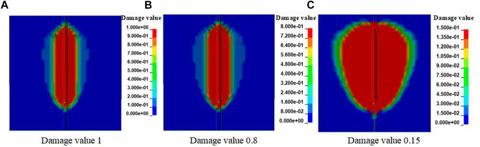
FIGURE 13. Damage area distribution of single-hole blasting.
To observe the over-break and under-break of two blasting schemes at different locations away from the tunnel contour, according to the tunnel damage cloud image, the damage peaks of the tunnel sections at 0, 20, 30, and 50 cm away from the tunnel contour line were extracted, as shown in Figure 14.
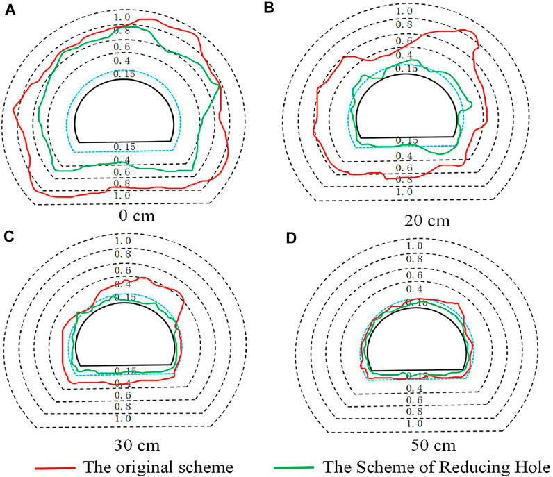
FIGURE 14. Different position damage peak values.
The damage variable peak of the original blasting scheme is higher than that of the reduced-hole layout scheme because the original blasting scheme has more blast holes, the superposition of effective stress is higher, and the cumulative damage caused in the retained rock mass is more serious, resulting in the increase in the damage variable. However, the maximum damage variable peak of the original blasting scheme is close to 1 at the tunnel contour line, the maximum damage peak at the tunnel contour line of the scheme of the reduced-hole scheme is 0.79 as shown in Figure 14A, and the damage values of the two schemes are more than 0.15. It can be observed that the rock mass of the two blasting schemes is all broken at the tunnel contour line, the phenomenon of under-excavation does not occur, and the broken blocks of rock in the original blasting scheme are too small at the tunnel contour line, so that flying stones are more likely to occur.
The damage peaks of the original blasting scheme 20, 30, and 50 cm away from the tunnel profile are 0.85, 0.41, and 0.22, respectively, and those for the hole-reducing blasting scheme 20, 30, and 50 cm away from the tunnel contour line are 0.23, 0.17, and 0.11. As shown in Figure 14B–D it can be seen that the peak of the original blasting scheme at a distance of 50 cm from the tunnel profile is more than 0.15 (the damage threshold of the plastic zone), which results in partial rock fragmentation in this position, and the maximum over-break thickness exceeds 50 cm, resulting in serious over-excavation. However, the maximum damage value of the hole-reducing blasting scheme was slightly larger than 0.15 at 30 cm from the tunnel contour line and a small part of the rock mass broke, while the damage peak at 50 cm from the tunnel profile was less than 0.15 and the rock mass did not break. This shows that the scheme controlled the maximum over-break thickness within 50 cm, which reduced the over-break.
5 Discussion
5.1 Influence of the distance
According to Hu (2019), when wedge-cutting blasting is used, the position of the cutting hole should not exceed half of the distance from the central axis of the tunnel to the side wall. Otherwise, drilling is difficult. With cutting hole spacing a ≤ B/2, where B is the width of the tunnel section, so the maximum distance between cutting holes is 6 m. To meet the cutting hole angle of 60°, the minimum distance between two rows of cutting holes is set at 4.2 m. To verify whether the safety distance d = 2.81 m from No. 13 and No. 14 cutting holes to the tunnel contour line was the optimal distance, in other words, to determine whether the cutting-hole spacing of 5 m was optimal, two numerical models, both with a cutting angle of 60° and with cutting-hole spacings of 4.2 (safe distance d = 3.10 m) and 6 m (safe distance d = 2.37 m), respectively, were established. As shown in Figure 15A, at the safe distance of 3.10 m, the damage value of the rock mass in the center of the heading face was close to 1; at the distance of Z = 1.8 m (Z = 0 in the center of the heading face), the rock mass was fully broken, but the damage value of the rock mass between the cutting hole and the auxiliary hole was small; at 3.3 m, the damage value of the rock mass between the cutting hole and the auxiliary hole was about 0.3, which caused the large fragmentation rate of the rock mass to be too high. The cutting hole could not provide a better freeing surface for the auxiliary hole, the clamping effect of the rock was significant, and the damage range of the peripheral hole was small after initiation, which led to under-excavation.
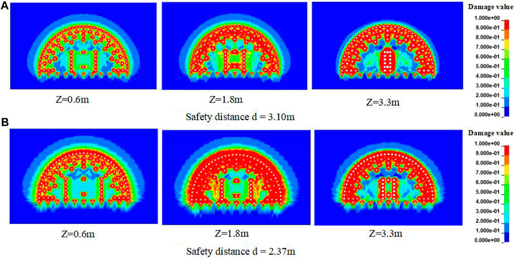
FIGURE 15. Damage cloud images of different safety distances.
When the safe distance was 2.37 m as shown in Figure 15B, the cutting hole was close to the auxiliary hole, and the effective stress superposition effect was more obvious when the cutting hole was detonated. The damage around the peripheral hole was obviously larger than that when the safe distance was 3.10 m, especially in Z = 1.8 m, the damage to the rock mass around the tunnel profile was very large, resulting in serious over-excavation of the tunnel.
5.2 Impact of the angle
The angle for wedge-cut blasting is between 60° and 80°. The optimal hole-layout angle
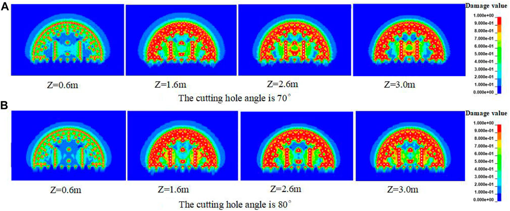
FIGURE 16. Damage cloud images with different cutting angles.
When the angle of the cutting hole was 80° as shown in Figure 16B, the damage value was about 0.15 at Z = 0.6 m, and the damage at the center of the heading face was less. At Z = 1.6 m, the damage value at the center of the heading face was about 0.4, and cracks appeared in this part of the rock mass. At Z = 2.6 m, the damage value of the center of the palm face was about 0.6. At Z = 3.0 m, the damage value was close to 0.7. The rock mass at the bottom of the cutting hole could not be collapsed, and the cutting angle was too large to provide a freeing face for the auxiliary hole.
5.3 Field applications
The original blasting scheme adopted three-stage compound cutting blasting. The cutting angles β were 69°, 72°, and 73°, respectively. The total number of holes was 131. The hole network layout is shown in Figure 17A. The blasting scheme of the reduced-hole layout extrapolated the wedge-shaped cutting hole to the maximum extent. The horizontal spacing of the cutting hole was 5 m, and the longitudinal distance was 0.6 m. The distance from the No. 13 and No. 14 cutting hole to the tunnel contour was 2.81 m. The cutting angle β was 60°, and the number of holes in the upper bench section was 105. The hole network layout is shown in Figure 17B.
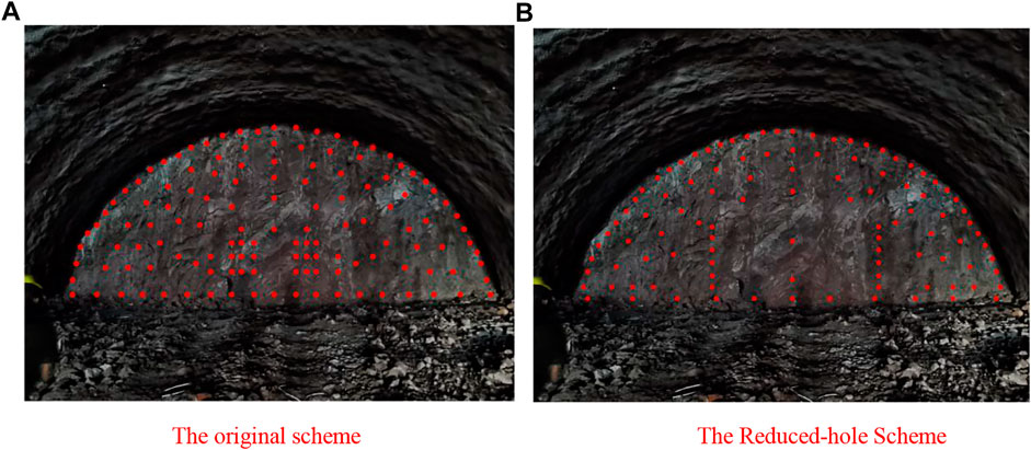
FIGURE 17. Hole network layout. (A) Original scheme. (B) Reduced-hole scheme.
Based on the aforementioned numerical simulation results, the article carried out the millisecond-delay blasting excavation method in the test section of the Baizhushan Tunnel. When the original blasting scheme was carried out, the average utilization rate of the blast hole was 78.3%, the unit consumption of explosives was 0.79 kg/m3, the average over-excavation thickness was 36.70 cm, the maximum over-excavation thickness was 60 cm, and there was no under-excavation as shown in Figure 18A. The authors applied the blasting scheme of the reduced-hole layout to the site for a total of five tests and counted the utilization rate of the blast hole. As shown in Table 7, the average utilization rate of wedge-cut holes was 81.9%, the average utilization rate of other blast holes was 91.2%, and the average explosive consumption was 0.72 kg/m3. The total station instrument was used to measure the over-/under-excavation in each part of the upper step as shown in Figure 18D, and the survey results are shown in Figure 18B. It was found that all of them were over-excavated, and there was no under-excavation. The reduced-hole blasting design scheme for the large-span section tunnel as proposed in this article can control the average over-excavation thickness within 20 cm, and the smooth surface-blasting effect is superior as shown in Figure 18C.
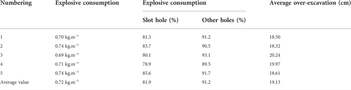
TABLE 7. Data after the on-site test.
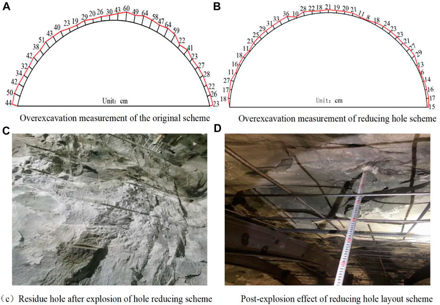
FIGURE 18. Damage diagram of the post-explosion effect.
6 Conclusion
(1) The reduced-hole layout blasting scheme forms better tunnel contours and cutting cavities after blasting and meets the requirements of 3.3 m footage, which can ensure the quality of tunnel formation. The number of holes in the original blasting scheme was 131, while the number of holes in the reduced-hole scheme was 105, and each cycle footage reduced the number of holes by 26, saving 0.7 h of drilling time.
(2) The peak of average effective stress at the positions of arch foot, hance, spandrel, and arch roof was 0.6 times that of the original blasting scheme, and the effective stress around the tunnel profile was lower, which reduced the damage to the retained rock mass.
(3) There was no under-excavation in the two blasting schemes, and the maximum over-excavation thickness of the original blasting scheme exceeded 50 cm. The maximum over-excavation thickness was controlled within 50 cm in the reduced-hole layout blasting scheme, which reduced the over-excavation.
(4) The reduced-hole layout blasting scheme was carried out in the test section of the Baizhushan Tunnel. The average blast-hole utilization rate of the wedge-cut hole was 81.9%, and that of the other blast holes was 91.2%, reducing the average explosive consumption from 0.79 to 0.72 kg/m3 and controlling the average over-break thickness within 20 cm. The blasting effect was superior.
Data availability statement
The original contributions presented in the study are included in the article/Supplementary Material; further inquiries can be directed to the corresponding author.
Author contributions
XL is the main author of this manuscript. The numerical model was analyzed and the initial manuscript was written by XL. TT and XT proposed the innovation of this project and analyzed the samples. QL established a numerical simulation model. XL, QL, and CX performed the uniaxial compression test, triaxial compression test, Brazilian splitting test, and SHPB test of slate.
Funding
The authors declare that this study received funding from the National Natural Science Foundation of China Regional Science Foundation (52064008) and China Guizhou Province high-level innovative talents (GCC [2022] 004-1). The funder had provided the field test.
Acknowledgments
The authors thank the Poly Xinlian Blasting Engineering Group Civil Explosion Engineering Laboratory and Poly Union Group Corporation Civil Explosion Engineering Laboratory for providing experimental venues for this article.
Conflict of interest
The authors declare that the research was conducted in the absence of any commercial or financial relationships that could be construed as a potential conflict of interest.
Publisher’s note
All claims expressed in this article are solely those of the authors and do not necessarily represent those of their affiliated organizations, or those of the publisher, the editors, and the reviewers. Any product that may be evaluated in this article, or claim that may be made by its manufacturer, is not guaranteed or endorsed by the publisher.
References
Banadaki, M. M. D. (2010). Stress-Wave induced fracture in rock due to explosive action. Toronto, Canada: University of Toronto.
Chen, H. (2021). Study on the influence of blasting excavation damage area on rock slope stability. Jiangxi, China: Nanchang University.
Chen, J., Zhang, J., and Li, X. (2016). Rock blasting damage model considering rock mass integrity and its application. J. Geotechnical Eng. 38 (05), 857–866. doi:10.11779/CJGE201605011
Cheng, P., Xie, L., and Li, X. (2021). Numerical investigation of the effect of eccentric decoupled charge structure on blasting-induced rock damage. J. Central South Univ. 29, 663. doi:10.1007/s11771-022-4947-3
Dong, M. (2019). Dynamic response analysis of surrounding rock and structure adjacent to tunnel excavation blasting. Xi'an, Shaanxi, China: Xi 'an University of Architecture and Technology.
He, Q. I. (2017). Rock damage mechanism and control due to excavation distrubance in deep tunnels. Wuhan, Hubei, China: Wuhan University.
He, R. (2017). Micro-vibration blasting control technology of multi-stage wedge cutting. Shandong, China: Shandong University of Science and Technology.
Hu, X. (2019). Optimization design study of blasthole layout for full section smooth blasting of rock tunnel. Tianjin, China: Tianjin University.
Ji, L., Zhou, C., Jiang, N., Lu, S., and Gutierrez, M. (2021). Numerical studies on the cumulative damage effects and safety criterion of a large cross-section tunnel induced by single and multiple full-scale blasting. Rock Mech. Rock Eng. 54 (09), 6393–6411. doi:10.1007/s00603-021-02630-9
Li, F., Hu, Z., and Chen, N. (2022). A study of fracture range of tunnel surrounding rock under blasting. Vib. impact 41 (08), 260–269.
Ling, J., Zhou, C., and Liu, C. (2020). Research and application of inverted T-cut blasting in large section tunnels. J. Huazhong Univ. Sci. Technol. Nat. Sci. Ed. 48 (02), 54–60.
Ling, J., Zhou, C., and Zhang, B. (2021). Study on dynamic response characteristics and damage effect of surrounding rock under large section tunnel blasting. J. Railw. 43 (07), 161–168. doi:10.3969/j.issn.1001-8360.2021.07.021
Lou, Q., Tao, T., and Tian, X. (2022). Research on numerical simulation method of lmestone impact failure based on HJC constitutive model. Blasting, 1–12.
Luo, S., Peng, Y., and Lu, W. (2021). Numerical simulation of blasting damage and damage mechanism of deep buried tunnel excavation. J. Rock Mech. Eng. (S1), 2760–2772.
Luo, Y., Li, X., and Xu, P. (2014). Study on deformation characteristics of surrounding rock considering cumulative damage effect. Rock soil Mech. 35 (11), 3041–3048.
Ma, C., Xie, W., Liu, Z., Li, Q., Xu, J., and Tan, G. (2020). A new technology for smooth blasting without detonating cord for rock tunnel excavation. Appl. Sci. 9, 6764. doi:10.3390/app10196764
Ma, W. (2022). The key technology development and prospect of drilling and blasting method in railway mountain tunnel. Railw. J. 44 (03), 64–85.
Meng, H., Hu, Y., Chen, J., Zhang, J., Li, H., and Cai, C. (2022). Numerical simulation study on parameter optimization of time sequential controlled blasting. Shock Vib. 3, 1–12. doi:10.1155/2022/8728953
National standard of the People 's Republic of China GB50299 (1999). Code for construction and acceptance of underground railway projects. Beijing, China: National standard of the People 's Republic of China.
Pan, C., Xie, L.-X., X.Li, , Liu, K., Gao, P.-F., and Tian, L.-G. (2022). Numerical investigation of effect of eccentric decoupled charge structure on blasting-induced rock damage. J. Cent. South Univ. 3, 663–679. doi:10.1007/s11771-022-4947-3
Ren, l., Zhao, Y., Wang, H., and Wang, D. (2022). Research on the attenuation law of blasting vibration in tunnel engineering. Arab. J. Geosci. 15, 631. doi:10.1007/s12517-022-09899-2
Shan, R., Zhao, Y., Wang, H., Dong, J., and Wang, D. (2022). Research on the attenuation law of blasting vibration in tunnel engineering. Arab. J. Geosci. 3, 631. doi:10.1007/s12517-022-09899-2
Wang, P. (2020). Optimization of blasting parameters of large cross-section tunnel wedge cutting. China, Guangxi, Nanning, Qingxiu: Guangxi University.
Wang, W., Zhang, H., and Li, X. (2021). Tension-compression damage model of rock under blasting load. J. Central South Univ. Nat. Sci. Ed. 52 (11), 3918–3929.
Wang, Z. (2016). Research on complex wedge cutting technology of super large section hard rock roadway. Taiwan: Nanhua University.
Wang, Z., Wang, H., Wang, J., and Tian, N. (2021). Finite element analyses of constitutive models performance in the simulation of blast-induced rock cracks. Comput. Geotechnics 135, 104172. doi:10.1016/j.compgeo.2021.104172
Xie, L. X., Lu, W. B., and Zhang, Q. B. (2017). Analysis of damage mechanisms and optimization of cut blasting design under high in-situ stresses. Tunn. Undergr. Space Technol. 66, 19–33. doi:10.1016/j.tust.2017.03.009
Yang, J., Dai, J., and Yao, C. (2022). Displacement mutation characteristics and energy mechanism of rock slope under blasting excavation disturbance. Explos. impact 42 (03), 138–149.
Yang, S. (1991). Dynamics base of rock blasting. Beijing: China Coal Industry Publishing House, 74–78.
Yang, Y., Liu, M., Zhang, G., and Li, Q. (2010). Optimization analysis of construction parameters of new large section tunnel adjacent to existing tunnel. Geotech. Mech. 31 (04), 1217–1226. doi:10.3969/j.issn.1000-7598.2010.04.037
Yuan, X. (2014). Tunnel wedge cutting blasting technology research. Anhui, China: Anhui University of Technology.
Keywords: large-span tunnel, SHPB test, numerical simulation, damage of surrounding rock, reduced-hole layout
Citation: Liu X, Tao T, Tian X, Lou Q and Xie C (2022) Layout method and numerical simulation study of reduced-hole blasting in large-section tunnels. Front. Earth Sci. 10:976419. doi: 10.3389/feart.2022.976419
Received: 23 June 2022; Accepted: 29 August 2022;
Published: 15 September 2022.
Edited by:
Chong Xu, National Institute of Natural Hazards, ChinaReviewed by:
Jagriti Mandal, Visvesvaraya National Institute of Technology, IndiaLixiang Xie, China University of Mining and Technology, China
Chao Yuan, Hunan University of Science and Technology, China
Copyright © 2022 Liu, Tao, Tian, Lou and Xie. This is an open-access article distributed under the terms of the Creative Commons Attribution License (CC BY). The use, distribution or reproduction in other forums is permitted, provided the original author(s) and the copyright owner(s) are credited and that the original publication in this journal is cited, in accordance with accepted academic practice. No use, distribution or reproduction is permitted which does not comply with these terms.
*Correspondence: Tiejun Tao, dGp0YW9AZ3p1LmVkdS5jbg==