 Shaorui Sun
 Jin Wang
 Haotian Fan
 Wuchao Wang
- College of Earth Science and Engineering, Hohai University, Nanjing, China
Engineering problems are related to the failure of geological material, especially that of jointed rock masses. To investigate the influence of confining stress and inclination angle β on cracking behavior and failure mechanism, triaxial compression tests are conducted on rock-like samples containing parallel opening flaws. There are two patterns, namely, tensile failure and tensile-shear failure, and each occurrence has an equal frequency. Nine crack modes are summarized, and the most special one is mode 8, which is mainly observed in samples with β = 60° at high confining pressure. Both the compressive strength and internal friction in samples with β = 60° are the smallest in the experiments, and those in samples with β = 65.31° based on the improved theory are the smallest. The compressive strength decreases with the increase of inclination angle β when 0°≤β≤60°; however, it increases as inclination angle β increases when 60°<β≤90°. This phenomenon is found in laboratory experiments and numerical tests and is almost even in accordance with theoretical results. Numerical compression tests are performed to investigate the influence of the width-to-length ratio of opening flaws on compressive strength and to verify the improved theory reliability. Compared numerical results with the two kinds of theoretical results, the width-to-length ratio has an obvious impact on compressive strength and the opening fracture intensity factor KⅠ.
1 Introduction
In geotechnical engineering, the occurrence of discontinuities in rock masses often results in a deterioration of strength. Compressive loading always contributes to the cracking of flaws, leading to rock mass failure (Lee and Jeon, 2011; Cao et al., 2015; Le et al., 2019a; Wan et al., 2019). In the past decades, a number of experimental and numerical researches on flawed rocks under uniaxial and biaxial loading have been carried out (Bahaaddini et al., 2013; Fu et al., 2016; Huang et al., 2016; Chenchen Huang et al., 2019; Chen et al., 2020; Bao et al., 2021). However, it is triaxial compression that is better in replying to the cracking behavior and is more realistic to investigate into fracture mechanism since flawed rock mass, especially in underground excavation, is in three-dimensional geological stress.
Some previous research studies have confirmed that the path of different loading has an impact on the development of cracks and the compressive strength of rock masses. Five coalescence crack patterns were found in uniaxial compression; however, four patterns were found in biaxial compression (Bobet and Einstein, 1998), which is one less shearing pattern than uniaxial compression. The compressive strength of flawed rock mass is mainly related to the mechanical properties of rock-like material and infill material, the geometrical parameters of flaws and confining stress. A comprehensive understanding of the influence of three kinds of materials infilling Naghdeh limestone samples on failure was made, and it was found that the weaker the infilling materials, the more the possibility of cracking in them (Haeri et al., 2020). Moreover, the compressive strength of samples with an inclination angle of 60° was the smallest one. Conventional triaxial compression was performed on jointed rocks with two parallel flaws; four crack coalesces modes were identified in samples with different inclination angles under the confining stress 0, 5, 10, 15, and 20 MPa (Huang and Yang, 2018). To investigate the discontinuities in cracking behavior, three groups of specimens containing different numbers of flaws (type A, granite specimens without cracks; type B, rock specimens with one inclined crack; type C, rock specimens with two parallel pre-existing cracks C) were prepared for experimental and numerical triaxial compression, and the failure of type C was constantly shear at any confining pressure (Yao et al., 2019). It was known from the abovementioned research that the compressive strength increased with the increase of confining stress. However, there are not enough investigations on the influence of pre-existing flaw geometry on the rock’s failure. Meanwhile, there are still difficulties in manual sample preparation due to the precise requirements of pre-existing flaws, especially opening flaws with a narrow width.
With the development of science and technology, more and more mature numerical simulation is one of the effective means to investigate the strength and deformation of rock mass (Guo et al., 2017; Cheng et al., 2019; Mu and Zhang, 2020; Wang et al., 2020). Compared to indoor experiments, there are fewer limitations to using the numerical method since many laborers and a specific area for the testing site are not required. Nine models with different joint numbers (1, 2, and 3) and joint angularities (0°, 45°, and 90°) were performed on the extended finite element method (X-FEM) (Haeri et al., 2020), and the failure process was fully demonstrated throughout. GPGPU was introduced to the finite element method to optimize modeling, and it was confirmed that more ductile flawed rock masses and less liable to fracture with an increase in confining pressure (Mohammadnejad et al., 2019). The interaction integral technique in ANSYS was applied to accurately predict the crack propagation paths and the mixed-mode stress intensity factors of jointed rock masses (Alshoaibi, 2021). As the failure mechanism of composite rocks can be effectively explained from the perspective of the migration of particles, the distribution of contact force, and the development of tensile cracks and shear cracks, the discrete element method is widely adopted to investigate the mechanical response of rock materials on the micro level (Camones et al., 2013; Cui et al., 2020). It was indicated that there were five failure modes, determined by the flaw’s orientation and step angle. Under triaxial compression, the cross-section of experimental specimens scanned by CT agreed with that of numerical models in PFC3D, and the numerical results well-revealed the failure mechanism of rock masses containing pre-existing flaws (Yan-Hua Huang et al., 2019). Therefore, numerical simulation has many advantages in the high accuracy of specimens’ preparation, making it possible for investigating the strength and failure mechanism of rock masses containing opening flaws.
In this study, rock-like specimens contacting four opening flaws were subjected to triaxial compression tests to investigate the effects of flaws’ inclination angle on compressive strength and cracking behavior in rock masses under different confining pressure. Types of cracks defined were used to determine the ultimate failure pattern, and the fracture theory of opening flaws was improved to make it more suitable for experimental results and reality. For verifying the reliability of this theory, numerical compression tests were performed. Numerical samples with min-width flaws were in high precision, and three width-to-length ratios were prepared to further understand the influencing factors of compressive strength. Results obtained from three methods (experiment, numerical simulation, and fracture theory) were expected to be compared and illustrated in the end.
2 Materials and methods
2.1 Specimens preparation
To reflect the brittle failure characteristics of rock mass with non-consecutive joints, cement mortar has been proved to be an ideal rock-like material for rock mechanics experiments. In this research study, specimens for triaxial loading tests were made of C32.5 Portland cement, fine sand, and water. The mechanical properties of the rock-like material with a cement-to-sand-to-water weight ratio of 1:2:0.4 were similar to those of sandstone are shown in Table 1. To reduce the effects of heterogeneity caused by formations of weak structural surfaces in the preparation process, the particle size of fine sand was selected to be less than 1 mm. Artificial flaws in specimens were prefabricated using a steel sheet with a width of 10 mm and a thickness of 1 mm, and the flat sheet of steel was fixed at the designed position. These samples were cured for 28 days in a tank with a temperature of 20°C to avoid an uneven shrinkage resulting from dehydration and cement hydration. Two mutually perpendicular strain gauges were attached to the surface of each specimen to monitor stains in the vertical and horizontal directions, respectively.
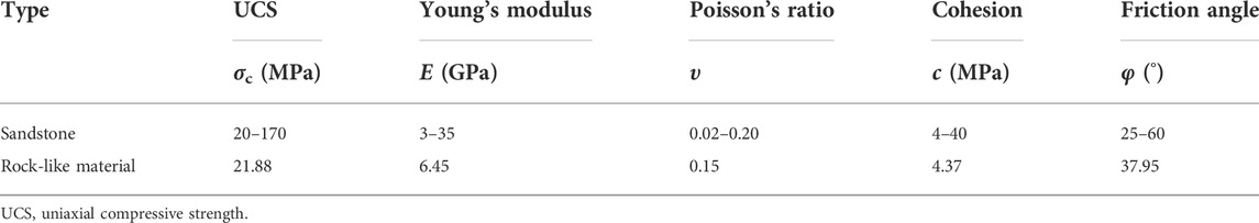
TABLE 1. Mechanical properties of the experimental material.
The geometry of specimens is a cylinder shown in Figure 1, with a dimension of 108 mm in height and 54 mm in radius. Centers of the four pre-existing flaws remain consistent all the time, and the distance between each of the two adjacent centers is 20 mm. The inclination angle β is illustrated in Figure 1. In this experiment, five kinds of jointed specimens are composed of flaws with different inclination angles, and intact samples are used as control groups to calibrate microscopic parameters in numerical simulation. The evolution of flaws into transfixion under loading conditions can be clearly observed with these specimens.
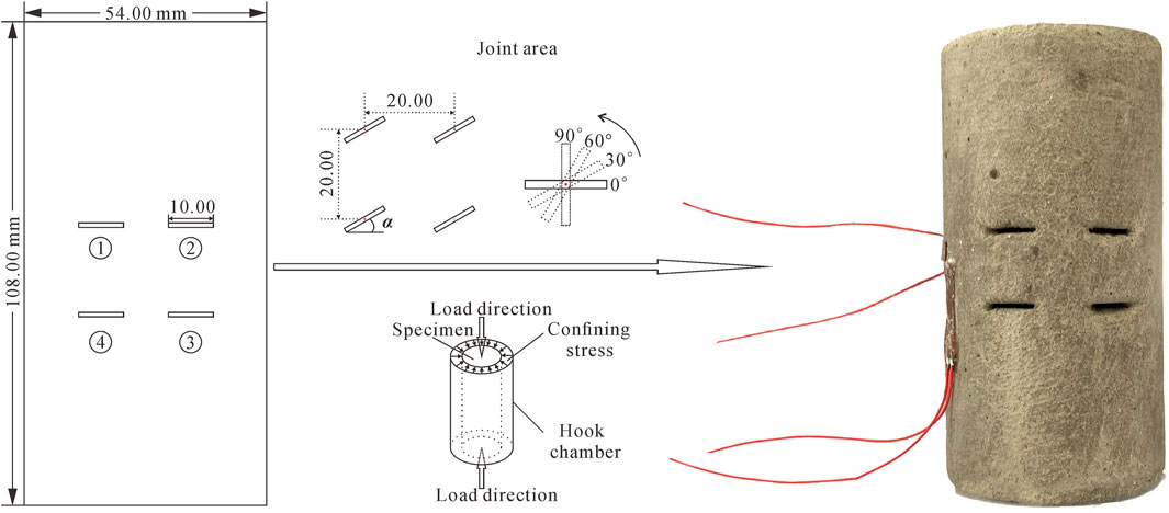
FIGURE 1. Detailed information of the specimen containing four flaws from plane view.
2.2 Testing procedure
Triaxial compression tests were conducted by the ELE device, and the loading rate was 0.1 ∼ 0.2 kN/s until the failure of specimens. It should be noted that centers of the Hooke chamber and of the jack were on the same line before loading to ensure force equality. In this experiment, confining stress was set to five levels which were 2.0, 4.0, 6.0, 8.0, and 10.0 MPa. Four kinds of flaws angle (0°, 30°, 60°, and 90°) were prefabricated to investigate the influence of inclination.
3 Experimental results
3.1 Samples coalescence and failure patterns
Compared to failure patterns under uniaxial compression, it is difficult to discover the crack mode which has been defined in previous studies (Peng et al., 2021; Wong and Einstein, 2009; Yang and Jing, 2010) that a tensile crack initiates from the flaw tips and then propagates along the major stress under the biaxial or triaxial loading, due to the effect of confining stress. Based on the ultimate crack modes of rock-like samples shown in Figure 2, the failure patterns are summarized into two types: one is composed of pure tensile cracks, and another one is a mixed coalescence of tensile cracks and shear cracks. Moreover, there is no failure pattern that is only caused by shear cracks. According to the mechanical properties of single crack propagation in Figure 3, a total of nine crack modes are found. Five modes are tensile (mode 1∼5), three modes are tensile-shear (mode 6∼8), and one of them is a spalling surface (mode 9) which often appears after tensile cracks. Modes I∼4, 6∼7, and 9 as common crack types of jointed rock masses failure have been summarized in many studies (Yang, 2011; Le et al., 2019b).
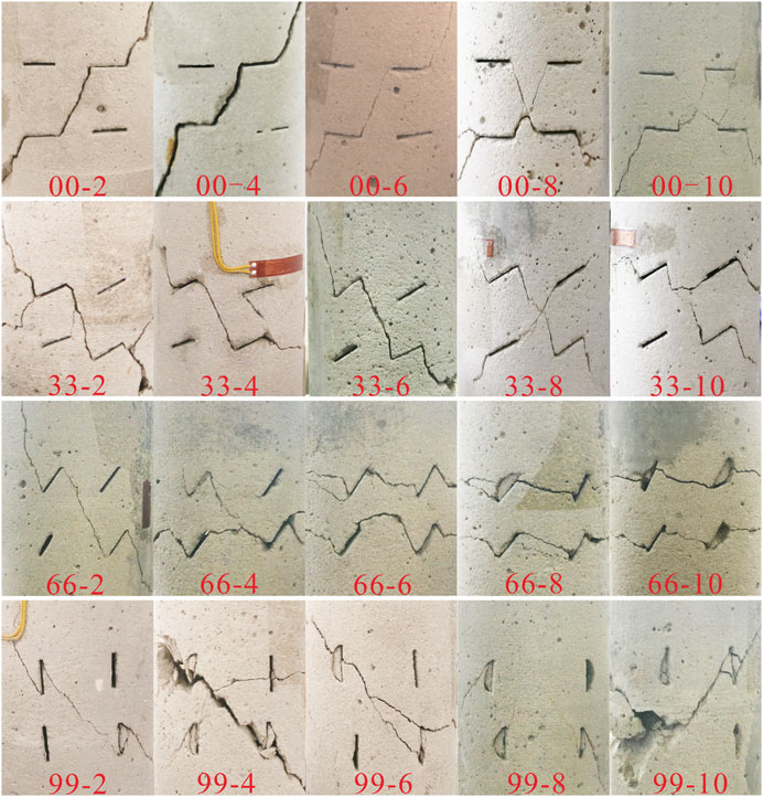
FIGURE 2. The ultimate failure of samples containing four opening flaws under triaxial compression. *The symbol “00-2” means that the sample with the inclination angle of 0° is loaded at the confining pressure of 2 MPa.

FIGURE 3. Crack types initiated from a single flaw under triaxial loading. (T Tensile crack, S Shear crack, Cs enveloping cracks, and Ss Surface spalling).
In mode 5, anti-wing cracks initiate from the two tips of pre-existing flaw and then extend to connection, and an elliptical crack surface is formed to envelop the flaw in the end. Short shear cracks shown in mode 7 are distributed near the pre-existing flaw and are almost parallel to it. Their appearance is always accompanied by the propagation of tensile cracks. Different from the lateral crack found in the previous research (Yang and Jing, 2010), it always develops at the end of the anti-wing crack in mode 8 and is gradually vertical to the major principal stress. The surface of the lateral crack is smooth, and combined with Figure 3, this crack is identified as a shear crack.
Cracking evolution of all samples subjected to triaxial compression tests is demonstrated in Figure 4 and is in accordance with the conclusion (Bobet and Einstein, 1998): The coalescence of cracks (including flaws) is the main reason leading to the ultimate failure of flawed rock mass under biaxial compression. All crack types for each specimen are summarized in Table 2. It is of note that tensile crack is the most dominant crack during the loading of a specimen. Especially when β = 90°, no matter what the confining pressure is, only the failure pattern that is composed of pure tensile cracks is discovered, and these two crack types (mode 3 and mode 5) are found in each specimen with that angle. When β = 0°, there is only mode 1 under low confining pressure; however, the major tensile crack is mode 2 when β = 30°. When the confining pressure is 8 and 10 MPa, these two crack types (mode 4 and mode 5) begin to appear in specimens with an inclination angle of 60°. With the increase of confining pressure, shear cracks gradually form in samples with β = 0°, 30°, and 60°, and the failure pattern changed from tensile failure to tensile-shear failure.
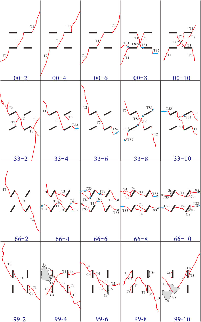
FIGURE 4. Various crack types observed in the ultimate failure of all samples.
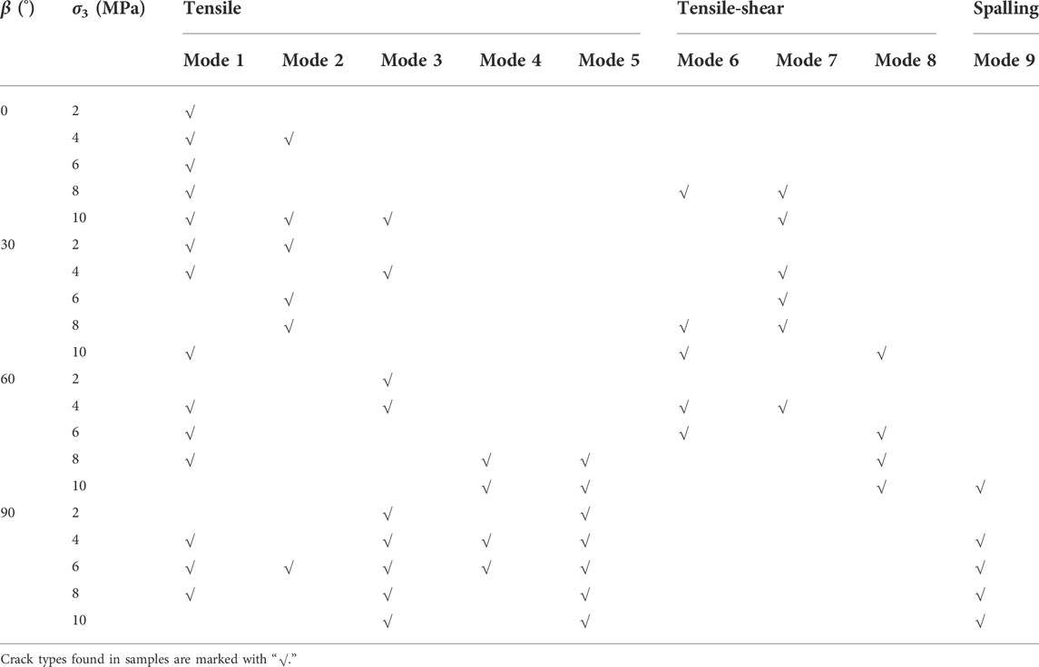
TABLE 2. Crack types of rock-like specimens containing four parallel flaws with different angles under triaxial loading test.
Based on the frequency of occurrence of crack types, mode 1 is thought to be the most dominant crack type in this study that just is not found in five kinds of samples (33-6, 33-8, 66-10, 99-2, and 99-10). The second type is mode 3, and the least one is mode 4. Mode 5 crack initiates in some samples with an angle of 60° at the large confining pressure (8 MPa, 10 MPa) and in all samples with an inclination angle of 90°. The main reason is that shear stress distributed on the pre-existing flaw surface increases as the inclination angle becomes larger. When the flaw is parallel to the axial loading, shearing is the strongest, leading it to be more prone to anti-wing cracks. Moreover, large confining pressure also contributes to shearing, resulting in anti-wing cracks intersecting to form an envelope surface. The special crack type, mode 8, is only observed in samples with β = 30° and σ3 = 10 MPa and in samples with β = 60° and σ3 = 6, 8, and 10 MPa.
3.2 Compressive strength and mechanical parameters of the specimens under confining loads
In order to obtain cohesion c and internal friction angle φ of samples, assuming that the relationship between confining pressure σ3 and the corresponding compressive strength σ1 is linear, linear regression is carried out in the least square method.
in the equation, a is the slope of the resultant line, and b is the intercept of the resultant line on the σ1. Furthermore, c and internal friction φ are derived based on the Mohr–Coulomb criterion.
The experimental results are processed according to the abovestated equations. Table 3 shows the compressive strength in the axial direction, cohesion c and internal friction angle φ of jointed rock-like specimens with different inclination angles under corresponding confining stress. The compressive strength of intact specimens is always larger than that of jointed rock mass, no matter what the confining pressure is. Variations of compressive strength and internal friction as the inclination angle of flaws increases are described in Figure 5A. The compressive strength of samples with β = 90° is larger than that of samples with β = 0°. Because the action of confining stress applied to samples is considered as leading opening flaws to internal closure, the specimen with β = 90° is easier to be closed on account of the flaw surface perpendicular to the confining pressure. Hence, the compressive strength, cohesion c and internal friction angle φ of samples with β = 90° approach to those of intact samples.
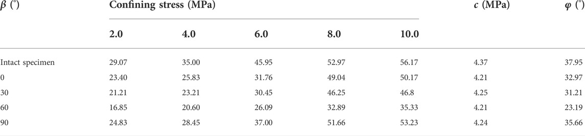
TABLE 3. Compressive strength and mechanical parameters of rock-like samples.
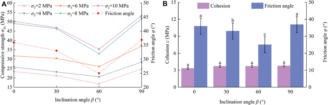
FIGURE 5. (A) Analysis of influence of inclination angle on shear strength parameters; (B) Variations of compressive strength and internal friction angle with inclination angle.
An obvious experimental phenomenon is found: There is a V-shaped characteristic that the peak strength first decreased when β<60° and then increased when β>60°. At any confining pressure, the compressive strength of samples with β = 60° is the minimum. The compressive strength of samples with β = 30° is very close to that of samples with β = 0°. It is a further observation that these curves in Figure 5A become flatter and flatter with the decrease of confining stress.
In Figure 5B, regression analysis is carried out for thoroughly investigating the influence of flaws angles, and the lowercase letters of the same column indicate the difference between cohesion, internal friction angle φ under the condition of different flaw angles (LSD): there is no significant effect of the inclination angle on cohesion (p > 0.05) but on internal friction angle (p < 0.05). The existence of pre-existing flaws does not have a significant effect on cohesion because cohesion is directly related to properties of rock material, such as mineral composition and density. The variation of the internal friction angle φ of jointed rock masses is in agreement with that of compressive strength, which decreases first and then increases with the increase of inclination, and the minimum one is found in samples with β = 60°. When the confining pressure σ3 and cohesion are determined, the compressive strength decreases as the internal friction angle decreases.
Lateral cracks in mode 8 initiate after anti-wing cracks and are defined as shear cracks because those surfaces are smooth and flat; moreover, this mode is mainly discovered in samples with an inclination angle of 60°. It is speculated that there is a concentration of shear stress at the anti-wing crack end. In addition, the ratio of compressive strength and confining pressure in samples with β = 60° is smaller than other samples at high confining pressure, as Table 4 indicates, resulting in the crack gradually propagating along the lateral direction.
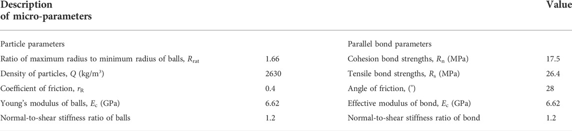
TABLE 4. Micro-parameters for bond parallel contact model.
4 Discussion
4.1 Fracture mechanical theory of rock masses containing opened flaws
The stress state of a simplified diagram for an inclined opening flaw in the infinite body under the compressive loading is shown in Figure 6. The flaw is described as an ellipse with 2a mm in length and 2b mm in width, where the biaxial loads σ1 and σ3 are distributed uniformly on the edges. The radius of curvature is ρ, and the angle of this flaw subjected to the direction of σ3 is represented by the symbol β.
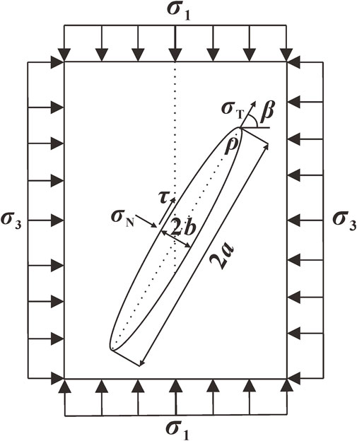
FIGURE 6. Sketch of force applied to opening type flaw.
Based on the elastic mechanic, it is known that transverse compressive stress σT, normal stress σN and shear stress τ in the far field of the ellipse are represented by the Eq. 4. The stress intensity factor of opening mode is KⅠ, and that of sliding mode is KⅡ. A tensile stress perpendicular to σT will be produced by the transverse compressive stress at the prefabricated flaw tip (Muschelišvilli, 1975), and k is introduced as the coefficient of pressure conductivity. The compressive stress σ is described by the following formula.
Under triaxial compression, tensile-shear failure is found to be an important ultimate failure pattern of experimental samples in this study. In this pattern, only shear cracks initiated under confining stress cause the ultimate failure of rock masses (Zhou, 1987).
In Eq. 7, λ12 is the compression-shear coefficient, and KⅡC is a material constant. Cracks always develop from the tip of the flaw, and when the width of the flaw is small, the tip can be considered as the endpoint of the major axis of the ellipse. Therefore, the radius of curvature ρ is expressed by b2/a, and the compression-shear coefficient λ12 is considered as the friction coefficient f of rock material. When σ3 = σ3C, the compressive strength σ1C of open-flawed rock mass is derived.
The angle βu corresponding to the minimum compressive strength is calculated by the following equations:when
hence,
For open-flawed samples with 10 mm in length and 1 mm in width, made of rock-like material with an internal friction angle of 37.95°, the βu calculated according to Eq. 11 is 65.31° at any confining pressure. In order to facilitate calculation, σ3C in Eq. 9 is set to 0. The infinite flawed rock masses under uniaxial condition is taken as the research object, and the fracture resistance R in Eq. 12, which is related to material properties and the width W mm of samples, is introduced to better describe the strength law (Ren et al., 2013). Both the compression-shear coefficient λ12, the width-to-length ratio k, and the fracture resistance R are dimensionless parameters.
Figure 7 demonstrates the relationship between compressive strength and inclination angle under uniaxial compression. This failure pattern occurs when the shear stress is larger than the frictional resistance, so when the inclination angle β is less than the internal friction angle φ, the compressive strength of the rock mass is close to the intact sample. It is clearly observed that the curves of inclination angle and compressive strength are V-shaped. When the angle increases from 0° to 65.31°, the compressive strength gradually decreases. When β > 65.31°, the compressive strength increases with the increase of inclination angle. This is also in accordance with the experimental phenomenon found in Figure 5A.
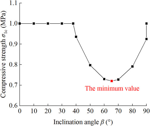
FIGURE 7. Relationship between fracture resistance of samples containing opening flaws and inclination angles.
4.2 Numerical verification tests for reliability
In the laboratory, when the pre-existing steel sheet is taken out from cement mortar, the opening flaw with a small width is easy to close. Therefore, numerical simulation is of great help in exploring the influence of flaw size. Numerical models are performed using the discrete element method to further verify relationships indicated in Eq. 9 between compressive strength and inclination angle and between compressive strength and flaws’ size. The finite element method is used to verify the reliability of taking the geometrical parameter k of opening flaws into account.
4.2.1 Influencing factors of compressive strength
A two-dimensional model with the size of 108 mm × 54 mm is filled with spherical particles named “balls” in PFC2D. The largest radius of balls is 0.332 mm, and the smallest is 0.2 mm. In the way of uniform distribution, it is constructed into a rectangular model with a density of 2630 g/cm3 and consisting of 21046 balls. For a good calibration of microscopic parameters in Table 4, intact specimens are subjected to uniaxial and biaxial compression tests, respectively, and the results of mechanical parameters are: The Poisson ratio 0.15, the elastic modulus 6.46 GPa, the uniaxial compressive strength 21.52 MPa, and the axial peak strength is 29.80 MPa under the confining pressure of 2 MPa. Compared to the results of experiments shown in Table 1, the absolute values of errors are small, not more than 3.0%.
In the numerical compression test, the length of the open flaw is 20 mm, and three width-to-length ratios (0.05, 0.1, and 0.2) are prepared for making a thorough inquiry into the influence of opening flaw geometry. Under the confining pressure of 8 MPa, there is an obvious finding that tensile-shear failure is the most common failure pattern in numerical samples. As Figure 8 shows, the minimum compressive strength is found in the numerical sample with β = 60°, no matter what the width-to-length ratio (0.05, 0.1, or 0.2) is. When the inclination angle grows from 0° to 60°, the compressive strength becomes larger; however, the compressive strength decreases with the increase of inclination angle when β > 60°. For samples with the same inclination angle, their compressive strength decreases as the width-to-length ratio of the opening flaw increases. These findings also can be illustrated by Eq. 9 and confirm that the geometrical parameter k has an important influence on the compressive strength of open-flawed rock mass.
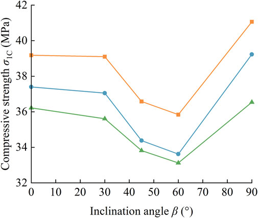
FIGURE 8. Effect between different width-to-length ratios and inclination angles on compressive strength of numerical samples containing opening flaw.
Figure 9 shows the ultimate modes of cracks in the numerical samples under the confining stress of 8 MPa. It is worth noting that with the increase of inclination angle, anti-wing cracks gradually develop near the pre-existing flaw. Shear failure is not found in any specimen, and mode 1 is the main failure pattern of specimens when β = 0°, while mode 5 is found in all the specimens with an inclination angle of 90°. When k = 0.05, the development of a through crack is the main reason for sample failure. When k = 0.2, only the samples with β = 0° are destroyed by a through crack, while the main failure pattern of other specimens is mode 5. Therefore, it can be assumed that increasing the inclination angle, together with increasing the width, both positively affect the shearing on the flaw surface while the flaw’s length is constant. Compared with others, the open flaw with an inclination angle of 90° is more susceptible to closure by the confining pressure, increasing its compressive strength.
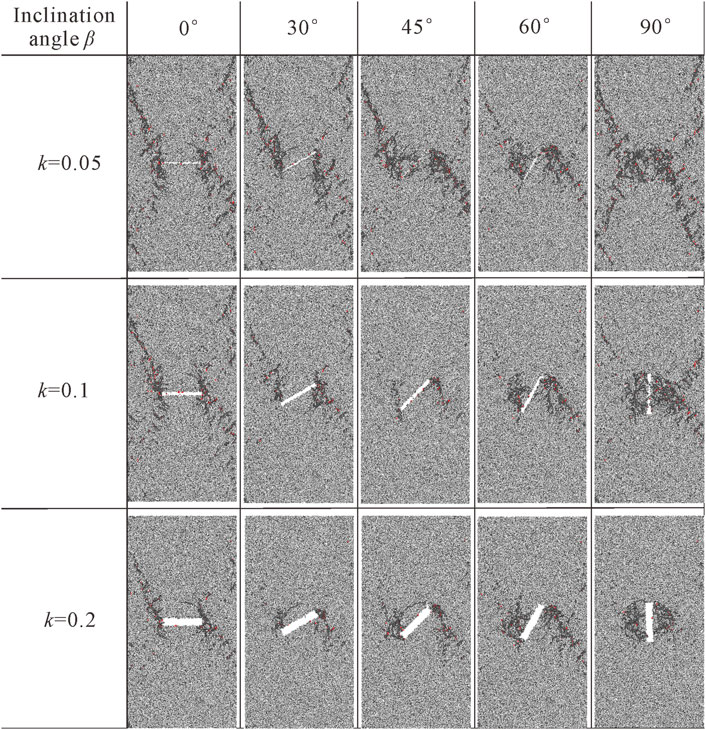
FIGURE 9. The ultimate failure modes of numerical samples with different width-to-length ratios and inclination angles.
4.2.2 Comparison of stress intensity factor
Without considering the influence of σT on the opening mode, the stress intensity factor of the opening mode is derived from the following equation. The improved effectiveness is investigated by ANSYS V19.2 in the finite element method. The material PLANE183 with eight nodes is used to deduct the singularity of the flaw tip, and details for meshing are demonstrated in Figure 10. The numerical model is a rectangle with a size of 108 mm × 54 mm, and the length of the pre-existing flaw is 20 mm.
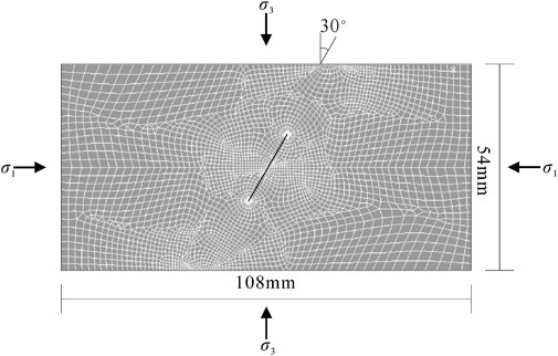
FIGURE 10. Meshing of the simulation model in ANSYS.
The mechanical parameters in Table 1 are applied to the contact analysis procedure, such as coefficient of friction, elastic modulus, and Poisson’s ratio. These two kinds of stress intensity factors of open-flawed rock-like samples with different inclination angles are obtained in the method of interaction analysis at a confining pressure of 8 MPa in Table 5. The opening fracture intensity factor KⅠ and the sliding fracture intensity factor KⅡ calculated from Eqs 6–13, respectively, are listed in Table 5. At present, the finite element method (FEM) is a mature method to calculate fracture mechanics of linear elastic material; therefore, the numerical results obtained by FEM are temporarily taken as true values, and the error analysis is carried out, respectively.
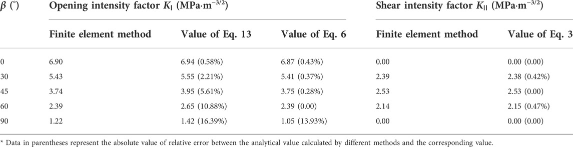
TABLE 5. Values of stress intensity factors derived from different methods and relative error between them.
It can be seen from Table 5 that the value calculated based on Eq. 6 is closer to the numerical value of the opening fracture intensity factor KⅠ compared with Eq. 13, especially when the inclination angle is less than 90°. The sliding fracture intensity factor KⅡ calculated by the finite element method is very close to the one calculated by Eq. 6. It indicates that the improved fracture theory of opening flaw is workable and reliable. Therefore, the flaw’s geometry is suggested to be considered as the influence factor of compressive strength of open-flawed rock mass, which makes the calculation more accurate.
5 Conclusion
A triaxial compressive test was carried out on rock-like specimens containing four parallel flaws, and nine crack modes and two failure patterns were found. The relationships between inclination angle and compressive strength and mechanical parameters, respectively, were summarized. Numerical biaxial tests were conducted to verify the reliability of the improved fracture theory of open-flawed rock mass.
(1) Most cracks initiated during triaxial loading are tensile, and there is no failure pattern composed of pure shear cracks. One of the two failure patterns is tensile, and the other is tensile-shear with an equal frequency of occurrence. All samples with an inclination angle β of 90° are tensile failure patterns. For samples with β = 0°, 30°, and 60°, shear cracks gradually appear, resulting in the tensile-shear failure at high confining stress.
(2) Five modes of crack types are tensile, three modes are tensile-shear, and one is spalling surface. Mode 1 is the most frequent crack type, but mode 8 is a special crack type that is mainly found in specimens with β = 60° at high confining pressure, where the lateral crack is shear initiating from the end of anti-wing tensile cracks. When confining stress σ3 is 6 MPa, 8 MPa, and 10 MPa, the ratio of compressive strength σ1 in samples with β = 60° is smaller than that of others, leading to the shear crack propagating along the lateral direction.
(3) Both compressive strength and internal friction angle φ in samples with β = 60° are the smallest ones, and those of samples with β = 90° are the largest, which also is the closet to intact specimens, followed by those of samples with β = 0°. However, the variation of inclination angle almost has no effect on the cohesion c of all samples.
(4) Considering the influence of transverse compressive stress σT, an improved fracture theory of open-flawed rock is proposed, which takes the geometrical parameters of flaws into account. Based on the mechanical properties of the experimental material, the compressive strength of a flawed sample with β = 65.31° is the smallest according to theoretical equations. Moreover, when 0°≤β≤65.31°, the compressive strength decreases with the increase of inclination angle; however, the compressive strength increases when 65.31°<β≤90°. This phenomenon is almost in accordance with the experimental results.
(5) The compressive strength decrease as the width-to-length ratio of the opening flaw increases when the numerical biaxial compression test is performed using the discrete element method. The opening fracture intensity factor KⅠ calculated by the improved theory is closer to the numerical value obtained by the finite element method compared to that calculated by traditional theory.
Data availability statement
The raw data supporting the conclusion of this article will be made available by the authors, without undue reservation.
Author contributions
SS designed this research study. JW wrote the manuscript, led the data analysis, and interpreted the results. HL provided funding acquisition. Numerical analysis was guided by JW, HF, and WW. All authors contributed to manuscript revision and approved it for publication.
Funding
The research is funded by the Natural Science Foundation of China (Grant No. 42007256) and China’s Postdoctoral Science Fund (No. 2021M690865) and supported by “The Fundamental Research Funds for the Central Universities” (No. B210201002).
Conflict of interest
The authors declare that the research was conducted in the absence of any commercial or financial relationships that could be construed as a potential conflict of interest.
Publisher’s note
All claims expressed in this article are solely those of the authors and do not necessarily represent those of their affiliated organizations, or those of the publisher, the editors, and the reviewers. Any product that may be evaluated in this article, or claim that may be made by its manufacturer, is not guaranteed or endorsed by the publisher.
References
Alshoaibi, A. M. (2021). Numerical modeling of crack growth under mixed-mode loading. Appl. Sci. 11 (7), 2975. doi:10.3390/app11072975
Bahaaddini, M., Sharrock, G., and Hebblewhite, B. K. (2013). Numerical investigation of the effect of joint geometrical parameters on the mechanical properties of a non-persistent jointed rock mass under uniaxial compression. Comput. Geotechnics 49, 206–225. doi:10.1016/j.compgeo.2012.10.012
Bao, M., Chen, Z. H., Zhou, Z. H., Zhang, L. F., and Wang, J. M. (2021). Timeliness of collinear crack propagation in rock mass. AIP Adv. 11, 065120. doi:10.1063/5.0050868
Bobet, A., and Einstein, H. H. (1998). Fracture coalescence in rock-type materials under uniaxial and biaxial compression. Int. J. Rock Mech. Min. Sci. 35, 863–888. doi:10.1016/S0148-9062(98)00005-9
Camones, L. A. M., Vargas, E. D. A., Figueiredo, R. P., and Velloso, R. Q. (2013). Application of the discrete element method for modeling of rock crack propagation and coalescence in the step-path failure mechanism. Eng. Geol. 153, 80–94. doi:10.1016/j.enggeo.2012.11.013
Cao, P., Liu, T. Y., Pu, C. Z., and Lin, H. (2015). Crack propagation and coalescence of brittle rock-like specimens with pre-existing cracks in compression. Eng. Geol. 187, 113–121. doi:10.1016/j.enggeo.2014.12.010
Chen, M., Yang, S. Q., Ranjith, P. G., and Zhang, Y. C. (2020). Cracking behavior of rock containing non-persistent joints with various joints inclinations. Theor. Appl. Fract. Mech. 109, 102701–102717. doi:10.1016/j.tafmec.2020.102701
Chenchen Huang, C. C., Yang, W. D., Duan, K., Fang, L. D., Wang, L., and Bo, C. J. (2019). Mechanical behaviors of the brittle rock-like specimens with multi-non-persistent joints under uniaxial compression. Constr. Build. Mater. 220, 426–443. doi:10.1016/j.conbuildmat.2019.05.159
Cheng, Y., Jiao, Y. Y., and Tan, F. (2019). Numerical and experimental study on the cracking behavior of marble with en-echelon flaws. Rock Mech. Rock Eng. 52, 4319–4338. doi:10.1007/s00603-019-01849-x
Cui, J., Jiang, Q., Li, S., Feng, X., Zhang, Y. L., and Shi, Y. E. (2020). Numerical study of anisotropic weakening mechanism and degree of non-persistent open joint set on rock strength with particle flow code. KSCE J. Civ. Eng. 24, 988–1009. doi:10.1007/s12205-020-1482-3
Fu, J. W., Chen, K., Zhu, W. S., Zhang, X. Z., and Li, X. J. (2016). Progressive failure of new modelling material with a single internal crack under biaxial compression and the 3-D numerical simulation. Eng. Fract. Mech. 165, 140–152. doi:10.1016/j.engfracmech.2016.08.002
Guo, S. F., Qi, S. W., Zou, Y., and Zheng, B. (2017). Numerical studies on the failure process of heterogeneous brittle rocks or rock-like materials under uniaxial compression. Materials 10, 378–390. doi:10.3390/ma10040378
Haeri, H., Sarfarazi, V., Ebneabbasi, P., Nazari maram, A., Shahbazian, A., Fatehi Marji, M., et al. (2020). XFEM and experimental simulation of failure mechanism of non-persistent joints in mortar under compression. Constr. Build. Mater. 236, 117500–117514. doi:10.1016/j.conbuildmat.2019.117500
Huang, Y. H., and Yang, S. Q. (2018). Mechanical and cracking behavior of granite containing two coplanar flaws under conventional triaxial compression. Int. J. Damage Mech. 28, 590–610. doi:10.1177/1056789518780214
Huang, Y. H., Yang, S. Q., and Zeng, W. (2016). Experimental and numerical study on loading rate effects of rock-like material specimens containing two unparallel fissures. J. Central South Univ. 23, 1474–1485. doi:10.1007/s11771-016-3200-3
Le, H. L., Sun, S. R., and Wei, J. H. (2019a). Influence of types of grouting materials on compressive strength and crack behavior of rocklike specimens with single grout-infilled flaw under axial loads. J. Mat. Civ. Eng. 31, 1–6. doi:10.1061/(ASCE)MT.1943-5533.0002554
Le, H. L., Sun, S. R., Xu, C. H., Li, L. Y., and Liu, Y. (2019b). Cracking behaviors and mechanical properties of rock-like specimens with two unparallel flaws under conventional triaxial compression. Adv. Civ. Eng. 2019, 1–15. doi:10.1155/2019/5849703
Lee, H., and Jeon, S. (2011). An experimental and numerical study of fracture coalescence in pre-cracked specimens under uniaxial compression. Int. J. Solids Struct. 48, 979–999. doi:10.1016/j.ijsolstr.2010.12.001
Mohammadnejad, M., Fukuda, D., Liu, H. Y., Dehkhoda, S., and Chan, A. (2019). GPGPU-parallelized 3D combined finite–discrete element modelling of rock fracture with adaptive contact activation approach. Comput. Part. Mech. 7, 849–867. doi:10.1007/s40571-019-00287-4
Mu, L. L., and Zhang, Y. M. (2020). Cracking elements method with 6-node triangular element. Finite Elem. Analysis Des. 177, 103421–110355. doi:10.1016/j.finel.2020.103421
Muschelišvilli, N. I. (1975). Some basic problems of the mathematical theory of elasticity. Leyden: Noordhoff International Publishing. doi:10.2307/2314307
Peng, K., Wang, Y. Q., Zou, Q. L., Cheng, Y. Y., and Song, X. (2021). Experimental study of energy dissipation characteristics and crack coalescence modes of cracked sandstone under different cyclic loading paths. Bull. Eng. Geol. Environ. 80, 5881–5895. doi:10.1007/s10064-021-02290-7
Ren, L., Xie, L. Z., and Ai, L. (2013). Preliminary study on strength of cracked rock specimen based on fracture mechanics. Eng. Mech. 30, 156–162. (in Chinese). doi:10.6052/j.issn.1000-4750.2011.07.0464
Wan, W., Liu, J., Zhao, Y. L., and Fan, X. (2019). The effects of the rock bridge ligament angle and the confinement on crack coalescence in rock bridges: An experimental study and discrete element method. Comptes Rendus Mécanique 347, 490–503. doi:10.1016/j.crme.2018.12.006
Wang, Y. X., Zhang, H., Lin, H., Zhao, Y. L., and Liu, Y. (2020). Fracture behaviour of central-flawed rock plate under uniaxial compression. Theor. Appl. Fract. Mech. 106, 102503–102518. doi:10.1016/j.tafmec.2020.102503
Wong, L. N. Y., and Einstein, H. H. (2009). Systematic evaluation of cracking behavior in specimens containing single flaws under uniaxial compression. Int. J. Rock Mech. Min. Sci. 46, 239–249. doi:10.1016/j.ijrmms.2008.03.006
Yan-Hua Huang, Y. H., Yang, S. Q., and Tian, W. L. (2019). Crack coalescence behavior of sandstone specimen containing two pre-existing flaws under different confining pressures. Theor. Appl. Fract. Mech. 99, 118–130. doi:10.1016/j.tafmec.2018.11.013
Yang, S. Q. (2011). Crack coalescence behavior of brittle sandstone samples containing two coplanar fissures in the process of deformation failure. Eng. Fract. Mech. 78, 3059–3081. doi:10.1016/j.engfracmech.2011.09.002
Yang, S. Q., and Jing, H. W. (2010). Strength failure and crack coalescence behavior of brittle sandstone samples containing a single fissure under uniaxial compression. Int. J. Fract. 168, 227–250. doi:10.1007/s10704-010-9576-4
Yao, W., Cai, Y. Y., Yu, J., Zhuo, J. F., Liu, S. Y., and Tu, B. X. (2019). Experimental and numerical study on mechanical and cracking behaviors of flawed granite under triaxial compression. Measurement 145, 573–582. doi:10.1016/j.measurement.2019.03.035
Keywords: opening flaw, crack type, compressive strength, fracture mechanism, numerical tests
Citation: Sun S, Wang J, Le H, Fan H and Wang W (2022) Experimental and numerical investigation on compressive strength and crack behavior of rock-like specimens with open flaws under confining loads. Front. Earth Sci. 10:972194. doi: 10.3389/feart.2022.972194
Received: 17 June 2022; Accepted: 25 July 2022;
Published: 25 August 2022.
Edited by:
Shuren Wang, Henan Polytechnic University, ChinaReviewed by:
Yingchun Li, Dalian University of Technology, ChinaDengke Wang, Henan Polytechnic University, China
Copyright © 2022 Sun, Wang, Le, Fan and Wang. This is an open-access article distributed under the terms of the Creative Commons Attribution License (CC BY). The use, distribution or reproduction in other forums is permitted, provided the original author(s) and the copyright owner(s) are credited and that the original publication in this journal is cited, in accordance with accepted academic practice. No use, distribution or reproduction is permitted which does not comply with these terms.
*Correspondence: Jin Wang, cGFydGljbGV3akBoaHUuZWR1LmNu