 Chang Su
 Zhuang Wu
 Hua Xu1,2
- 1State Key Laboratory of Mining Response and Disaster Prevention and Control in Deep Coal Mine, Anhui University of Science and Technology, Huainan, China
- 2School of Mechanical Engineering, Anhui University of Science and Technology, Huainan, China
It is known that, long-distance concrete pipeline transportation often causes pipe blocking accidents. For the problem of pipeline blockage, we have invented a swirl speed-increasing device. In this study, the discrete element method was used to calibrate the parameters of the contact model through the slump bucket experiment, and a discrete element model of horizontal pumping concrete was established. Based on the particle unit, the flow-promoting mechanism of the swirl speed-increasing device was studied, and the effects of the pumping speed, the volume fraction of coarse aggregate and the wind speed output of the device on the movement state of the particles and the flow-promoting distance were analyzed. The results show that the maximum velocity and flow-promoting distance of the particle unit increase with the increase of pumping speed and wind speed, and decrease with the increase of the coarse aggregate volume fraction. When the pumping speed and wind speed are large, the installation distance of the flow promoting device should be increased. When the volume fraction of concrete aggregate is large, the installation distance of the flow promoting device should be shortened. Our swirl speed-increasing device can solve the problem of pumping concrete pipeline blockage. The discrete element model of pumping concrete established in this study can well reflect the motion state of the concrete unit in the pipeline, which verifies the applicability of the discrete element model. The numerical simulation conclusion in this paper can avoid system energy waste and pipeline blockage caused by improper selection of device installation spacing.
1 Introduction
In the construction of underground engineering, the roadway is usually supported by shotcrete (Su., 2018). Concrete has good pumpability, which allows us to pump concrete to the job site. Concrete is a complex mixture of coarse aggregate (crushed stone, pebbles), fine aggregate (sand), cement, water and various admixtures in a certain proportion. In pipelines, concrete is prone to blockage and segregation. This will not only cause damage to the pipeline, but also seriously affect the efficiency of underground construction.
Researchers (Feys et al., 2016; Chen et al., 2019; Kim et al., 2019; Secrieru et al., 2019) mainly use pipeline experiments to study pumped concrete. Choi et al. (2014) established a 1000 m horizontal pipeline for pumping concrete experiments, and studied the effect of electromagnetic fields on the pumpability of concrete. The results show that the application of electromagnetic fields is very effective in improving the pumpability of concrete. In (Choi et al., 2013a), the researchers studied the properties of the lubricating layer based on the coil experiment, and the results showed that the thickness of the lubricating layer is independent of the speed. The results of literature (Choi et al., 2013b) show that shear-induced particle migration contributes to the formation of the lubricating layer.
Studying concrete flow through field tests is costly and time-consuming, and it is difficult to study concrete flow under various working conditions, and it is impossible to directly observe it. With the development of computer technology, the numerical simulation method is widely used in the research of pumping concrete. Wei et al. (2019) regards concrete as a single-phase fluid and studies the influence of rheological parameters on pumping pressure loss of concrete by using CFD (Computational Fluid Dynamics). The results show that viscosity is the main factor affecting pump pressure loss. Aggregate occupies a large proportion in concrete, and it is inappropriate to treat concrete as a single-phase fluid in research. Sun et al. (2020) simplified the concrete into a two-phase fluid, and Wang et al. (2009a), on the basis of the Euler-Euler model, approximated the particles (pebble, sand) in the concrete into a fluid phase, so as to simplify the research structure. Purpose. But in this model, particles such as aggregates are still treated as fluids, which do not match the actual situation. Subsequently, Wang et al. (2009b) in his research, based on the Euler-Euler model and the Euler-Lagrange model, compared water and mortar as fluids, and compared aggregates with larger particle sizes as particles. Wear mechanism of concrete pumping elbow. Although the influence of aggregates is considered in the article, the particles are regarded as particles, and the particle phase is a sparse phase, accounting for a small volume fraction. However, in fact, the volume fraction of aggregate in concrete is very large, and the above research is far from the actual situation. It can be found from the above literature that the fluid dynamics model can describe the speed and pressure distribution of pumped concrete in the pipeline well, and the formation mechanism of the lubricating layer in the pipeline can be studied. However, it is difficult for the dynamic model to describe the movement of the aggregate in the pipeline, and the model is quite different from the actual concrete.
There are various numerical models for fresh concrete (Gram and Silfwerbrand, 2011), and the discrete particle model is used by scholars in the study of concrete flow. The discrete element method was proposed by Cundall and Strack (1979). Japanese scholar Nabeta applied the discrete element method to the study of fresh concrete for the first time. Du et al. (2020) established a local discrete element model for pumping concrete and studied the pumping pressure loss of straight pipe sections. Cao et al. (2015) divided the particles into two parts, mortar and aggregate, established a discrete element model of local pipelines for pumping concrete, and studied the effect of aggregate volume fraction on the flow behavior of fresh concrete. The results show that with the increase of the volume fraction of coarse aggregate, the degree of pipe wear increases. Zhan et al. (2019) studied the effects of pipe geometry parameters, aggregate parameters and pumping speed on the flow behavior of concrete pipes. Tan et al. (2014) used the concrete discrete element model to try to study the mechanism of pipe wear. Hao et al. (2021) analyzed the trajectory of coarse aggregate in the pipeline and revealed the influence of coarse aggregate on the pumping performance of concrete. However, the research of pumped concrete based on discrete particle model is carried out on the basis of local modeling. The research content covers the effects of pipeline geometric parameters, pumping speed, and concrete aggregate size on concrete rheological properties and pipeline wear. Although the discrete element method makes up for the deficiency of the CFD method and can directly observe the flow behavior of concrete, there is no excellent solution to the clogging problem of pumped concrete.
This study proposes a method to improve pipeline fluidity for pumped concrete. By installing a swirl speed-increasing device along the pipeline, energy is input to the pipeline system to increase the flow speed of the pumped concrete. The rational layout of the flow-promoting device is the main problem discussed in this paper. This paper adopts the discrete element method and based on the discrete element model of horizontally pumped concrete to analyze the relationship between the attenuation of concrete flow energy and the volume fraction of coarse aggregate, the pumping speed and the wind speed of the swirl speed-increasing device, and reveal the promotion of the swirl speed-increasing device.
2 The structure of swirl speed-increasing device
As shown in Figure 1, the swirl speed-increasing device consists of an accelerating cavity and an air bleed ring. The acceleration cavity is connected with the pumping pipeline, and there are a plurality of air holes around the acceleration cavity, and the air holes form a certain angle with the axis of the pipeline. The air bleed ring is connected with the acceleration chamber. The bleed air ring has two air inlets, and the high-pressure air enters the bleed air ring through the air inlet, and then enters the pipeline through the air hole. The airflow forms a swirl in the duct. Swirl increases the flow rate of concrete.
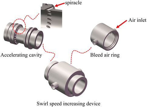
FIGURE 1. Structure diagram of the swirl speed-increasing device.
3 The principles of discrete elements method
The discrete element method is based on discontinuous media mechanics. Particles are treated as rigid bodies, obeying Newton’s second law:
Here the
Particle velocity:
Angular velocity of particles:
The position of the particle:
The angle of the particle:
Here the
The force on the particle in the fluid is
Here the
The drag coefficient is defined as:
where
The particle Reynolds number is:
Where
4 The discrete element model of fresh concrete
4.1 The particle model
The fresh concrete is divided into two parts: aggregate and mortar. In the discrete element model, aggregates and mortars were simulated with two different particle sizes (Cao, et al., 2015; Tan, et al., 2015). The discrete element model of fresh concrete established in this study is shown in Figure 2. The particle parameter values are shown in Table 1.
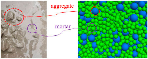
FIGURE 2. The particle model.
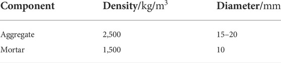
TABLE 1. Particle parameter values.
4.2 The contact model and parameter calibration
In the discrete element model, the particle-to-particle or particle-to-wall relationship is defined by the contact model. When using the discrete element model to simulate concrete, it is necessary to calibrate the parameters of the contact model (Cui et al., 2017; Cui et al., 2018; Cui et al., 2020). In this paper, the PFC3D software is used to establish the discrete element model of fresh concrete, and the linear contact model built into the software is used. The contact force is divided into linear force
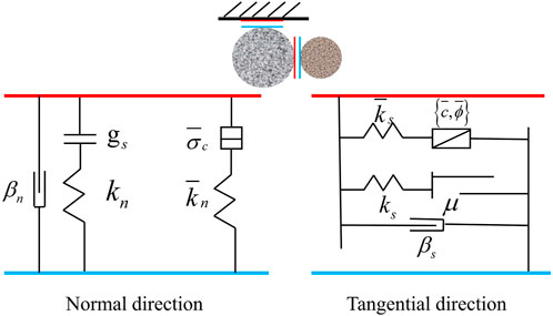
FIGURE 3. The contact model.
Linear Parallel Bond Model reverts to Linear Model. All contact force-displacement relationships in the contact model follow the force-displacement law. In this paper, Linear Model is used to simulate the interaction between aggregates, and Linear Parallel Bond Model is used to simulate the interaction between aggregate-mortar and mortar-mortar.
As shown in Figure 4, the contact parameters are calibrated using the results of standard slump experiments (Cao, 2014; Su et al., 2021). The upper diameter of slump bucket is 100 mm, the bottom diameter is 200 mm, and the height is 300 mm. Before the experiment, we use water to wet the inside of the slump bucket and step on the pedal to fix the slump bucket. The clump bucket is filled with fresh concrete in three times. The fresh concrete needs to be compacted after each filling. After the clump bucket has been filled, the fresh concrete around the clump bucket needs to be removed. Then the clump bucket is lifted vertically and smoothly. When the fresh concrete is no longer flowing, the vertical drop height of the fresh concrete is measured and the vertical drop height of the fresh concrete is the slump value. PFC3D generates a particle model with the same size as the slump bucket, and the slump bucket is set as a wall. The wall moves upward at a uniform speed, and after 7 s, the particle speed is basically 0. The experimental parameters are compared with the simulation parameters, and the results are shown in Table 2. The concrete slump value obtained by numerical simulation is 207 mm, and the concrete slump value obtained by field experiment is 198 mm, with a relative error of 4.5%. The results show that the calibrated concrete discrete element model can accurately simulate the flow behavior of fresh concrete. The specific contact parameter values are shown in Tables 3, 4, 5.

FIGURE 4. Slump experiment and its numerical simulation.
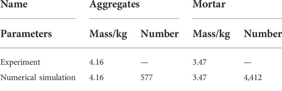
TABLE 2. Comparison table of experimental and simulated parameters.
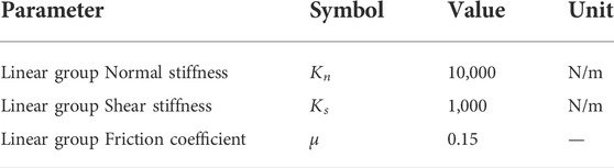
TABLE 3. Aggregate-aggregate contact parameter.
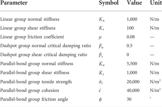
TABLE 4. Aggregate- mortar contact parameters.
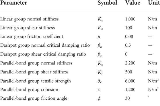
TABLE 5. Mortar- mortar contact parameters.
5 Numerical simulation
In underground construction works, fresh concrete is pumped to the work site. The pipeline is up to 100 m long. We establish the concrete discrete element model of the entire pipeline, which will result in a large amount of calculation and high time cost. In this paper, a local discrete element model of pumping concrete is established based on the horizontal straight pipe to simulate the motion state of concrete in the horizontal pipe.
5.1 Geometric model
As shown in Figure 5, the diameter of the pipe is 125 mm and the length is 20 m. The research adopts the grading method to generate a section of concrete particle collection on the left side of the pipeline. The length of the fresh concrete unit is 1 m. Study 1 m behind the particle element, set up the fluid grid. The mesh simulates that the concrete is accelerated as it passes through the swirl booster. The specific parameters of the grid are shown in Table 6.
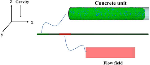
FIGURE 5. Geometric model.
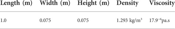
TABLE 6. Grid parameters.
5.2 The process of numerical simulation
As shown in Figure 6, the aggregate of concrete particles generated in the pipeline is pushed forward by the wall at a constant speed V. When the aggregate of concrete particles is accelerated as it passes through the fluid grid, the particles are in the acceleration phase. The coupling of the fluid and the particles is single-phase, and the fluid is not subject to the force of the particles. After the particles pass through the fluid mesh, the velocity of movement begins to decrease. The next wall comes into contact with the particles, and the particles are pushed forward again by the wall at a constant speed V, and after a period of time, the particles return to the stable stage. During the simulation process, the velocity of the wall is constant. The distance between the acceleration segment and the constant segment is set as the flow-promoting distance for the aggregate of concrete particles. The authors use qualitative methods to study the relationship between the flow-enhancing distance, pumping speed, volume fraction of coarse aggregate and the wind speed of the swirl speed-increasing device.
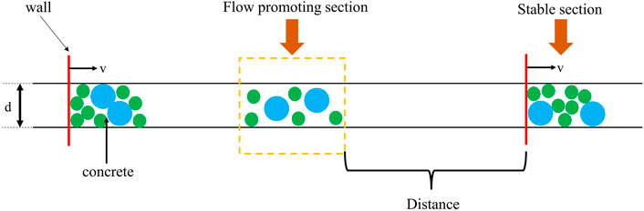
FIGURE 6. The process of numerical simulation.
6 Discussion
During the concrete pumping process, the pumping speed and the volume fraction of coarse aggregate have a great influence on the fluidity of concrete. The wind speed input by the swirl speed-increasing device determines the energy input of the concrete pipe unit. Based on the pumping concrete unit, this paper studies the effects of pumping speed, coarse aggregate volume fraction and wind speed on the aggregate displacement of concrete particles.
6.1 Influence of pumping speed
When the volume fraction of coarse aggregate is 40% and the wind speed is 40 m/s, the wall speed is changed to study the effect of pumping speed on the distance between the swirl speed-increasing device installed. The horizontal pumping speed is generally less than 1.0 m/s (Choi et al., 2013a; Choi et al., 2013b; Jiang et al., 2021). The pumping speeds of this simulation are taken as 0.2 m/s, 0.4 m/s, 0.6 m/s, 0.8 m/s, and 1.0 m/s respectively. The simulation results are shown in Figure 7.
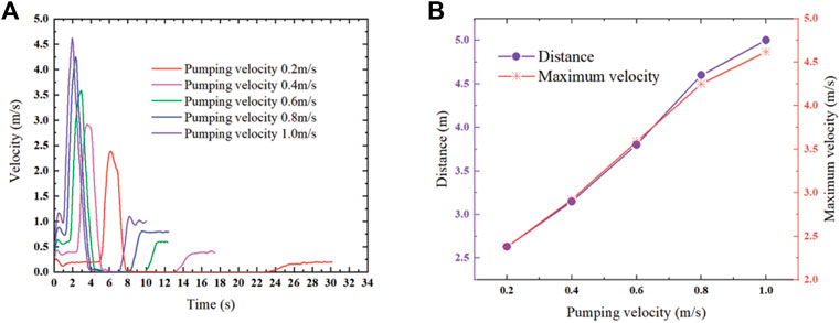
FIGURE 7. (A) Relationship between particle velocity and time at different pumping speeds; (B) Maximum particle velocity and device installation distance at different pumping speeds.
It can be seen from Figure 7 that the maximum speed of the particle unit increases with the increase of the pumping speed. As the difference between the pumping speed and the airflow speed decreases, the maximum speed change of the particle unit decreases gradually with increasing pumping speed. As the pumping speed increases, the installation distance of the device also increases. The experimental results show that when the pumping speed is larger, the installation spacing of the device should be increased.
6.2 Influence of coarse aggregate volume fraction
When the wind speed is 40 m/s and the pumping speed is 0.6 m/s, the influence of the volume fraction of coarse aggregate on the installation spacing is studied. The volume fraction of coarse aggregate is 30%, 40%, 50%, 60%, and 70% of five sets of data. The simulation results are shown in Figure 8.
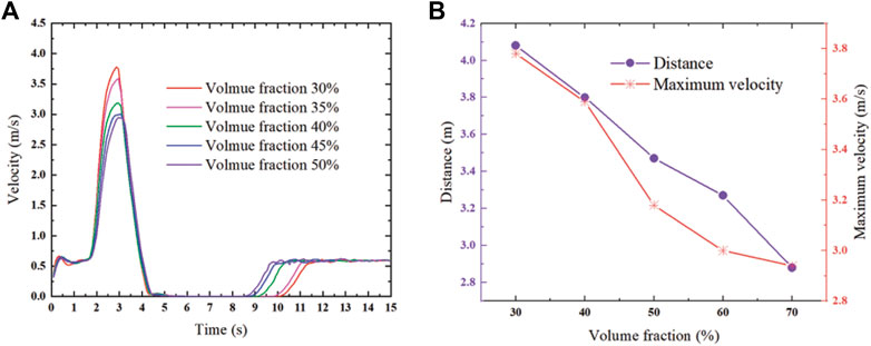
FIGURE 8. (A) The relationship between particle velocity and time for different coarse aggregate volume fractions; (B) maximum particle velocity and device installation distance for different coarse aggregate volume fractions.
It can be seen from Figure 8 that in the deceleration stage, the velocity curves of the particle units overlap, and the velocity change rates of the particle units with different coarse aggregate volume fractions are the same. In the acceleration stage, the smaller the volume fraction of coarse aggregate, the larger the velocity change rate of the particle unit. Because the aggregate volume fraction is smaller, the mass of the particle unit is smaller. The experimental results show that the effect of aggregate volume fraction on particle units is mainly manifested in the acceleration stage. The maximum velocity of particle units with different volume fractions is not significantly different, the maximum velocity of particle units decreases with the increase of volume fraction, and the installation distance of the device decreases with the increase of concrete coarse aggregate volume fraction.
6.3 Influence of wind speed of the swirl speed-increasing device
When the volume fraction of coarse aggregate is 40% and the pumping speed is 0.6 m/s, the influence of the output wind speed of the device on the installation distance of the device is studied. The wind speed is 30 m/s, 35 m/s, 40 m/s, 45 m/s, and 50 m/s five sets of data, the simulation results are shown in Figure 9.
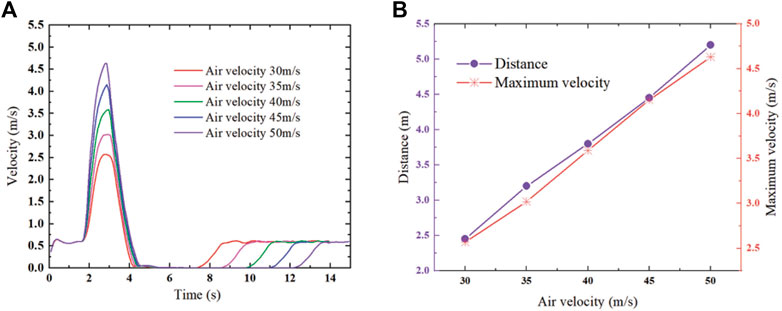
FIGURE 9. (A) The relationship between different wind speeds, particle speed and time; (B) Different pumping speeds, maximum particle speed and installation spacing of devices.
It can be seen from Figure 9 that in the acceleration stage, the five groups of particle units reach the maximum speed at almost the same time. The greater the air velocity, the greater the velocity change rate of the particle unit. During the deceleration stage, the five velocity curves are nearly parallel, and the velocity change rates of the particle units are the same. This shows that the influence of the device is mainly manifested in the acceleration stage. The maximum velocity of the particle unit increases with the increase of air velocity of the device, and the installation distance increases with the increase of the air velocity. The relationship between the maximum velocity of the concrete unit and the air velocity of the swirl speed-increasing device is close to linear.
7 Conclusion
The installation spacing of the swirl speed-increasing device is proportional to the pumping speed and the wind speed output by the device, and inversely proportional to the coarse aggregate volume fraction. When the pumping speed and wind speed are high, the installation distance of the device should be increased. When the volume fraction of concrete aggregate is large, the installation distance of the device should be shortened. The discrete element model of pumping concrete established in this study can well reflect the motion state of the concrete unit in the pipeline, which verifies the applicability of the discrete element model. Our swirl speed-increasing device can solve the problem of pumping concrete pipeline blockage. The numerical simulation conclusion in this paper can avoid system energy waste and pipeline blockage caused by improper selection of device installation spacing.
Data availability statement
The original contributions presented in the study are included in the article/Supplementary Material, further inquiries can be directed to the corresponding author.
Author contributions
CS: Conceptualization, methodology, software, investigation, formal analysis, writing—original draft; ZW: Data curation, writing—original draft; HX: Investigation; LW: Resources, supervision.
Funding
The project was supported by the Independent Research Fund of the State Key Laboratory of Mining Response and Disaster Prevention and Control in Deep Coal Mines (No. SKLMRDPC20ZZ06) and the program in the Youth Elite Support Plan in Universities of Anhui Province (No. gxyq2020013) and Innovation fund of Anhui University of Science and Technology (2021CX2054).
Acknowledgments
The authors are very grateful to the editor and anonymous reviewers for their valuable advice.
Conflict of interest
The authors declare that the research was conducted in the absence of any commercial or financial relationships that could be construed as a potential conflict of interest.
Publisher’s note
All claims expressed in this article are solely those of the authors and do not necessarily represent those of their affiliated organizations, or those of the publisher, the editors and the reviewers. Any product that may be evaluated in this article, or claim that may be made by its manufacturer, is not guaranteed or endorsed by the publisher.
References
Cao, G. D. (2014). On the rheology and thixotropy of fresh concrete by Discrete Element Method. China. Xiangtan University. [master’s thesis].[China].
Cao, G. D., Zhang, H., Tan, Y. Q., Wang, J. Q., Deng, R., Xiao, X. W., et al. (2015). Study on the effect of coarse aggregate volume fraction on the flow behavior of fresh concrete via DEM. Procedia Eng. 102, 1820–1826. doi:10.1016/j.proeng.2015.01.319
Chen, J., Xie, H., Guo, J., Chen, B., and Liu, F. (2019). Preliminarily experimental research on local pressure loss of fresh concrete during pumping. Measurement 147, 106897. doi:10.1016/j.measurement.2019.106897
Choi, M. S., Kim, Y. J., and Kwon, S. H. (2013b). Prediction on pipe flow of pumped concrete based on shear-induced particle migration. Cem. Concr. Res. 52, 216–224. doi:10.1016/j.cemconres.2013.07.004
Choi, M. S., Roussel, N., Kim, Y. J., and Kim, J. K. (2013a). Lubrication layer properties during concrete pumping. Cem. Concr. Res. 45, 69–78. doi:10.1016/j.cemconres.2012.11.001
Choi, M. S., Yu, S. K., Kim, J. H., Kim, J. S., and Kwon, S. H. (2014). Effects of an externally imposed electromagnetic field on the formation of a lubrication layer in concrete pumping. Constr. Build. Mat. 61, 18–23. doi:10.1016/j.conbuildmat.2014.02.071
Cui, W., Ji, T. Z., Li, M., and Wu, X. I. (2017). Simulating the workability of fresh self-compacting concrete with random polyhedron aggregate based on DEM. Mat. Struct. 50 (1), 92. doi:10.1617/s11527-016-0963-9
Cui, W., Yan, W. S., Song, H. F., and Wu, X. I. (2018). Blocking analysis of fresh self-compacting concrete based on the DEM. Constr. Build. Mater. 168, 412–421. doi:10.1016/j.conbuildmat.2018.02.078
Cui, W., Yan, W. S., Song, H. F., and Wu, X. I. (2020). DEM simulation of SCC flow in L-Box set-up: Influence of coarse aggregate shape on SCC flowability. Cem. Concr. Compos. 109, 103558. doi:10.1016/j.cemconcomp.2020.103558
Cundall, P. A., and Strack, O. D. L. (1979). A discrete numerical model for granular assemblies. Geotechnique 29 (1), 47–65. doi:10.1680/geot.1979.29.1.47
Du, T., Yei, H., Sun, T. P., Xu, M. L., and Zhang, L. M. (2020). Study of the pressure loss of the horizontal pumping pipe. J. Wuhan Univ. Technol. 42 (08), 69–75. doi:10.3963/j.issn.1671-4431.2020.08.011
Feys, D., Khayat, K. H., and Khatib, R. (2016). How do concrete rheology, tribology, flow rate and pipe radius influence pumping pressure? Cem. Concr. Compos. 66, 38–46. doi:10.1016/j.cemconcomp.2015.11.002
Gram, A., and Silfwerbrand, J. (2011). Numerical simulation of fresh SCC flow: Applications. Mat. Struct. 44 (4), 805–813. doi:10.1617/s11527-010-9666-9
Hao, J., Jin, C. Y., Li, Y., Wang, Z. G., Liu, J. L., and Li, H. W. (2021). Simulation of motion behavior of concrete in pump pipe by DEM. Adv. Civ. Eng. 2021, 1. doi:10.1155/2021/3750589
Jiang, S. Q., Chen, X. D., Cao, G. D., Tan, Y. Q., Xiao, X. W., Zhou, Y. P., et al. (2021). Optimization of fresh concrete pumping pressure loss with CFD-DEM approach. Constr. Build. Mater. 276, 122204. doi:10.1016/j.conbuildmat.2020.122204
Kim, J. H., Han, S. H., and Choi, B. I. (2019). Influence of pumping pressure on the viscosity curve and rheological stability of mortar incorporating polycarboxylate. Cem. Concr. Compos. 105, 103419. doi:10.1016/j.cemconcomp.2019.103419
Secrieru, E., Mohamed, W., Fataei, S., and Mechtcherine, V. (2019). Assessment and prediction of concrete flow and pumping pressure in pipeline. Cem. Concr. Compos. 107, 103495. doi:10.1016/j.cemconcomp.2019.103495
Su, C. (2018). Key parameters analysis om wet spraying machinery nozzle and shotcrete quality control research. China. Anhui university of science and technology. [dissertation]. [China].
Su, C., Zheng, X. K., Xiong, L., and Zhao, W. K. (2021). Research on concrete slump based on discrete element method. J. Phys. Conf. Ser. 1952 (4), 042078. doi:10.1088/1742-6596/1952/4/042078
Sun, Y., Yue, X. N., and Hu, D. (2020). CFD analysis of liquid-solid two-phase flow in concrete volute of water turbine. China Rural Water Hydropower 2020 (5), 6. doi:10.3969/j.issn.1007-2284.2020.05.030
Tan, Y. Q., Cao, G. D., Zhang, H., Wang, J. Q., Deng, R., Xiao, X. W., et al. (2015). Study on the thixotropy of the fresh concrete using DEM. Procedia Eng. 102 (C), 1944–1950. doi:10.1016/j.proeng.2015.06.138
Tan, Y. Q., Song, J. H., Zhang, H., Wang, J. Q., Deng, R., and Yang, D. M. (2014). Numerical study of wear process on pipe wall in concrete pumping using DEM. China Mech. Eng. 25 (15), 2091–2097. doi:10.3969/j.issn.1004-132X.2014.15.020
Wang, A. L., Yu, X. H., Wang, J. W., and Yang, X. (2009a). Simplified numerical simulation in concrete multi-phase mixing drum based on quasi-fluid solid two-fluid mode. J. Tongji Univ. Nat. Sci. 37 (2), 182–186.
Wang, A. L., Yu, X. H., Yu, Z. Y., Li, Y. W., and Liu, F. X. (2009b). The wear mechanism of concrete pumping pipe under the conditions of multiphase fluid. J. Shanghai Jiaot. Univ. 43 (2), 4.
Wei, Z. Y., An, X. P., Shi, C. J., Wu, B., and Yuan, Q. (2019). Pressure loss prediction of fresh concrete pumping based on CFD simulation. Mater. Rep. 33 (22), 48–53.
Keywords: pumping, concrete, discrete element method, pneumatic, flow enhancement
Citation: Su C, Wu Z, Xu H and Wang L (2022) Analysis of influencing factors of pneumatic flow enhancement of pumped concrete based on discrete element method. Front. Earth Sci. 10:968085. doi: 10.3389/feart.2022.968085
Received: 13 June 2022; Accepted: 14 September 2022;
Published: 30 September 2022.
Edited by:
Chongchong Qi, Central South University, ChinaReviewed by:
Naveen Mani Tripathi, Rajiv Gandhi Institute of Petroleum Technology, IndiaNatt Makul, Phranakhon Rajabhat University, Thailand
Copyright © 2022 Su, Wu, Xu and Wang. This is an open-access article distributed under the terms of the Creative Commons Attribution License (CC BY). The use, distribution or reproduction in other forums is permitted, provided the original author(s) and the copyright owner(s) are credited and that the original publication in this journal is cited, in accordance with accepted academic practice. No use, distribution or reproduction is permitted which does not comply with these terms.
*Correspondence: Zhuang Wu, MjAyMDIwMDUwMkBhdXN0LmVkdS5jbg==