 Zhang Jun
 Wang Yiliang1
94% of researchers rate our articles as excellent or good
Learn more about the work of our research integrity team to safeguard the quality of each article we publish.
Find out more
ORIGINAL RESEARCH article
Front. Earth Sci., 04 August 2022
Sec. Geohazards and Georisks
Volume 10 - 2022 | https://doi.org/10.3389/feart.2022.954547
This article is part of the Research TopicGeological Disasters in Deep Engineering Mechanism, Warning and Risk mitigationView all 39 articles
The manipulator is the key component of the anchor drilling robot to automatically complete the anchoring operation underground. Due to the complexity of its motion equation and the limitations of its control strategy, the real-time pose and the positioning accuracy of the manipulator are inferior, which seriously restricts the safety, efficiency, and speed of roadway excavation. In order to improve the positioning accuracy and realize the optimal efficiency of the manipulator, this article designs a manipulator structure with four degrees of freedom. With the help of the D-H method and the intelligent parameter setting method, this article carries out the basic theoretical research on the kinematics and the fractional order FOPID control algorithm of the manipulator of the mining roof bolter, and formulates a manipulator motion control strategy. At the same time, combined with numerical simulations and field experiments, we explore the robustness and control efficiency of the hydraulic system of the manipulator under the working conditions of a harsh environment and limited space, and reveal that the intelligent optimization algorithm can control the motion state of the manipulator more accurately and stably after the parameters of the fractional order FOPID controller are positively determined. This study effectively solved the dynamic model uncertainty caused by time-varying internal parameters and external loads of the hydraulic servo system, optimized and reconstructed the structure and motion coefficient parameters of the manipulator, and revealed the control mechanism of a precise spatial positioning and online trajectory planning of the hydraulic servo system of the manipulator. Compared with the traditional PID control algorithm, this algorithm has a faster response speed and better expected track tracking ability. This research lays a theoretical foundation for the precise positioning and automatic support of the manipulator, and also provides a reference for the design of similar motion control algorithms.
The intellectualization of coal mines is the core technical support for the high-quality development of China’s coal industry (Wang et al., 2019; Liu et al., 2021). Intelligent equipment and support technology of mining are key factors for coal intellectualization, and the roadway support theory and technology have always been the core of the coal mine strata control (Kang, 2007; Wang et al., 2018; Wang et al., 2020; Yang et al., 2022). In the “Catalog of Key Research and Development of Coal Mine Robots” (Author Anonymous, 2019; Li et al., 2019; Ge and Hu, 2020), it clearly points out the need to vigorously advance the research and development of coal mining, tunneling, transportation, safety control and rescue, and 38 kinds of coal mine robots, which is an important way to achieve the coal mines’ intellectualization. It is a key method to solve the problems of roadway excavation, support imbalance and high labor intensity to use the manipulator of anchor drilling robot on accurate location, and the completion of the automatic anchoring work, replacing the traditional manual completion of automatic positioning and support work of the drilling frame (Zhang et al., 2019; Zhang and Li, 2019).
Compared with developed countries, the ineffective bolt support in some coal mines in China has led to many roof falling accidents. While the main reason is that the existing support operations still rely on manual demolition, with the installation of drill pipes or bolts, bolt fastening, and other processes, with a great danger. The Guiding Opinions on Accelerating the Intelligent Development of Coal Mines clearly points out that the development of an anchor drilling support robot is an effective way to solve the key problems of slow speed and high labor intensity of roadway excavation.
Based on the guidance of the support theory, the bottleneck problem to be solved is to complete the automatic anchoring work with the use of an anchor drilling manipulator for precise positioning, replacing the traditional manual to complete of the drilling frame space positioning, and automatic support work. Since presently, the drivage speed and coal quantity have increases, so new requirements have been put forward for the way of the operation, process time, and the safety of the anchor drilling manipulator. Especially in harsh or limited spaces, manipulator ends need to accurately find the 22 mm diameter hole in the roof, effectively avoid the grid reinforced at the same time, and ensure that the drilling time does not exceed 3 min. However, in the process of drilling and anchoring by a manipulator-replacing manual operation, due to limitations in the formulation of control strategy, the real-time pose and positioning accuracy of the manipulator are inferior, essentially because the research studies are not sufficient in the fields of structural design, motion law, and control mechanism of the anchor drilling manipulator.
In recent years, the way to control the motion of the manipulator is a research hotspot with great significance. Because of its uncertainties in parameter uptake and external interference, the manipulator is a complex research object featuring high non-linearity, multi-variability, and high coupling. In order to make the manipulator in a specific action, it is necessary to control the hydraulic cylinder and hydraulic motor at each joint of the manipulator to cooperate with each other to complete the corresponding rotation angle of each joint. Presently, the manipulator structure has become increasingly complex, and the
With the gradual development of artificial intelligence technology and its wide application in the industrial field, a large number of efficient optimization algorithms have emerged, such as the genetic algorithm (Zhang et al., 2002; Yin et al., 2014a; Luo et al., 2021), particle swarm optimization algorithm (Feng et al., 2015; Al-Saggaf et al., 2020; Feng et al., 2022), search algorithm (Wu and Huang, 2021), and whale algorithm (Li et al., 2021). Applying the intelligent optimization algorithm to controller parameter tuning can greatly improve the control effect. Whale algorithm is a kind of meta-heuristic optimization algorithm, which has the characteristics of strong robustness, simple structure, and few control parameters. Most scholars (Dalir and Bigdeli, 2020; Bushnaq et al., 2021; Nguyen et al., 2021) have applied the whale algorithm and achieved successful examples in the field of continuous domain problem optimization.
To sum up, many experts have conducted in-depth research studies on the method of the intelligent control PID parameter adjustment and achieved a lot of results, but the control method of the drilling and anchor manipulator completing automatic support operation underground needs further research. This is mainly due to some particularity of the drilling and anchoring manipulator working underground: 1) limited space and a complex environment; 2) The end of the anchor drilling mechanical arm is mainly connected with the automatic drill frame. Due to the dead weight of the end and the drilling force of about 20,000 n, the arm end will vibrate greatly, making it difficult to achieve accurate control; 3) Underground electrical parts need explosion-prevention treatment, especially sensors. Compared with sensors on the ground, many performance indicators are difficult to achieve, so it will affect the accurate positioning of the drilling and anchoring manipulator in the roadway space. It seriously restricts the application of intelligent control technology in an underground coal mine robot.
In order to realize the goal of rapid spatial positioning and trajectory tracking of the manipulator, the intelligent control technology of the drilling anchor manipulator is studied. According to the spinor theory, the joint coordinate system and coordinate transformation matrix expression of the manipulator are established by using the D–H method, and the point cloud diagram of the manipulator workspace is solved by using the Monte Carlo algorithm. Based on the independent joint control theory, the single input single output system model of the hydraulic motor/cylinder at the joint of the manipulator is designed by using the MATLAB Simulink software and fractional order FOPID control technology. This article analyzes four intelligent optimization algorithms based on the genetic algorithm (GA), particle swarm optimization (PSO), whale algorithm (WOA), and search algorithm (GPS), evaluates the three dynamic indexes of standard deviation, overshoot, and stability time, and analyzes the effect of step influence under different control combination strategies of the hydraulic motor/oil cylinder. The simulation results show that the optimization ability of the
Mining roof bolter is suitable for automatic support of the top and side walls of the mine tunnel in an underground coal mine, and can realize accurate identification and positioning technology of the manipulator hole location through binocular stereo vision. The structure of the machine is shown in Figure 1. The manipulator connected the frame with the translation pair and the rotation pair realizes the support work of the automatic drilling frame, and ensures the support work of the top and side walls of the roadway with different heights and widths in the mine environment.
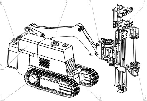
FIGURE 1. Structural diagram of the mine anchor drill frame.
1-Variable frequency speed-regulating traveling mechanism, 2-Electrical control system, 3-Connecting rod, 4-Automatic drill frame, 5-Frame, 6-Driving operation and monitoring mechanism, 7-Rotary reducer, 8-Anchor rod silo.
During mining roof bolter into the mine roadway, firstly, it is driven to the work scheduled area, after being stable, the manipulator controlled by the hydraulic system to automatically drill stands up to the right height through the rotary gear reducer to adjust the automatic drill’s stand posture. Then, the automatic drill starts to work on the working surface, and finally completes the mine roadway support work.
The manipulator is the main working structure of the equipment to realize the automatic support of the top and side walls of the roadway. The positioning system of the manipulator is the important factor to ensure that mining roof bolter can meets the working requirements and work quality. It is required that the displacement working accuracy offset of the manipulator shall not be more than 5 mm, and the displacement working accuracy offset of the manipulator end shall not be more than 10 mm. In addition, as the bad environment in the mine roadway, frequent vibration, and changeable load, a manipulator structure with five degrees of freedom is specially designed to meet the actual requirements of the aforementioned working process. The manipulator is mainly composed of a connecting rod, rotary reducer, coupling, automatic drilling frame, and so on. Its structural diagram is shown in Figure 2.

FIGURE 2. Structure diagram of the manipulator.
1 - Frame; 2 - Connecting rod; 3 - Rotary reducer; 4 - Connection shaft; 5-Automatic drilling rig.
The frame is set at the lower end of the whole manipulator as the main body supporting the whole manipulator; the connecting rod is connected through the shaft, and the hydraulic cylinder provides power which can rotate
In accordance with the principles and parameters of the
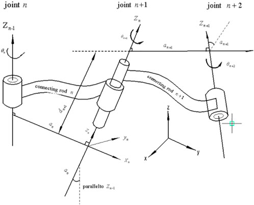
FIGURE 3. Schematic diagram of the
The homogeneous transformation matrix is expressed as
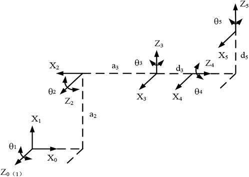
FIGURE 4. Establishment of a joint coordinate system of the manipulator by using the
Based on Table 1, the transformation relation matrix

TABLE 1.
All revolute joints of the manipulator in this article are represented by the
The simplified model of the manipulator of the mining roof bolter is shown in Figure 5. When the angle
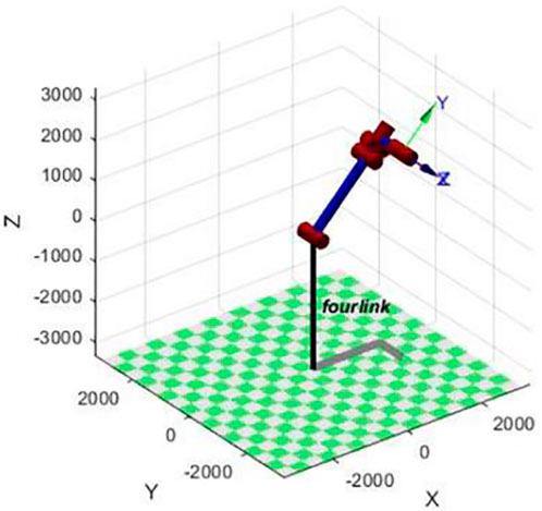
FIGURE 5. Five degrees of freedom manipulator.
To describe the working space of the manipulator of the mining roof bolter, the root of the manipulator is set as
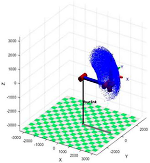
FIGURE 6. Cloud diagram of the manipulator movement space.
From Figures 7–9, it can be seen that the working range of the manipulator of mining roof bolter is
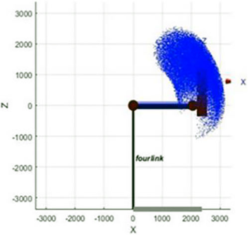
FIGURE 7. Spatial cloud diagram of the ZOX surface motion.
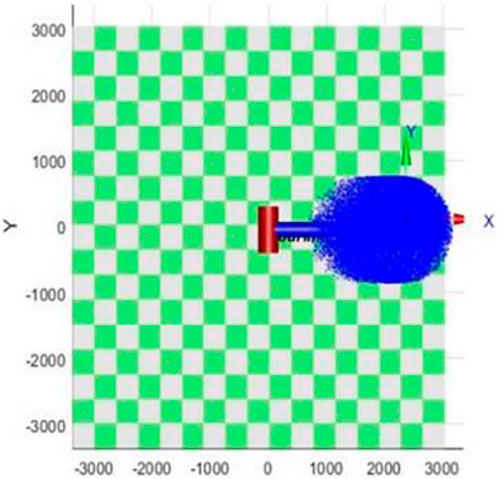
FIGURE 8. Spatial cloud diagram of the YOX surface motion.
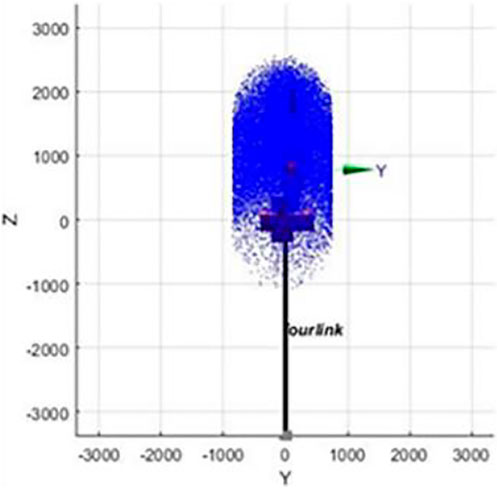
FIGURE 9. Cloud diagram of the ZOY plane motion space.
As a branch of the control field, fractional order control has been widely used in the design of different types of controllers (Yin et al., 2014b; Al-Saggaf et al., 2020; Sheng et al., 2021) for its advantages such as flexibility and precise parameter adjustment, increasing system stability margin and enhancing system robustness, etc. Fractional order
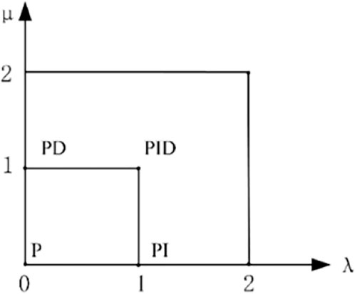
FIGURE 10. Order value range of the FOPID controller. The mathematical expression of FOPID is given.
Compared with the traditional
There are many kinds of parameter tuning methods. With the development of intelligent and control technology, according to the regulation characteristics of the algorithm itself, it is mainly divided into a traditional method tuning and an intelligent optimization algorithm tuning, and the latter one is widely used for its adaptability. The four intelligent optimization algorithms, genetic algorithm (GA), particle swarm optimization (PSO), whale algorithm (WOA), and search algorithm (GPS), have been used for real-time parameter tuning to obtain the optimal value. The parameter tuning principle of the four intelligent optimization algorithms is shown in Figure 11, and the flow chart of the intelligent optimization algorithm for tuning the FOPID parameters is shown in Figure 12. The specific mathematical theories and related expressions of the four intelligent optimization algorithms such as the whale algorithm will not be repeated.
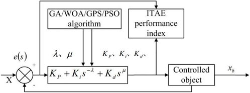
FIGURE 11. Parameter setting principle of the intelligent optimization algorithm.

FIGURE 12. Flow chart of the intelligent optimization algorithm for tuning.
In this article, genetic algorithm
For the optimization algorithms used in different control strategies, an objective function is usually set to select the optimal value. The common error performance indicators include ISE (square deviation integral), ITSE (time square deviation integral), IAE (absolute deviation integral), ITAE (time absolute deviation integral), etc. In servo control, the ITAE (time absolute deviation integral) performance index weights the error, so that the error signal converges to zero as soon as possible. Therefore, this article takes the ITAE performance index as the objective function for parameter tuning (Semmari et al., 2017) as shown in Figure 11.
Here, the specific parameters of each algorithm are set as follows:
(1)
TABLE 2. Mathematical modeling parameter table of the fractional integer order of the hydraulic motor.
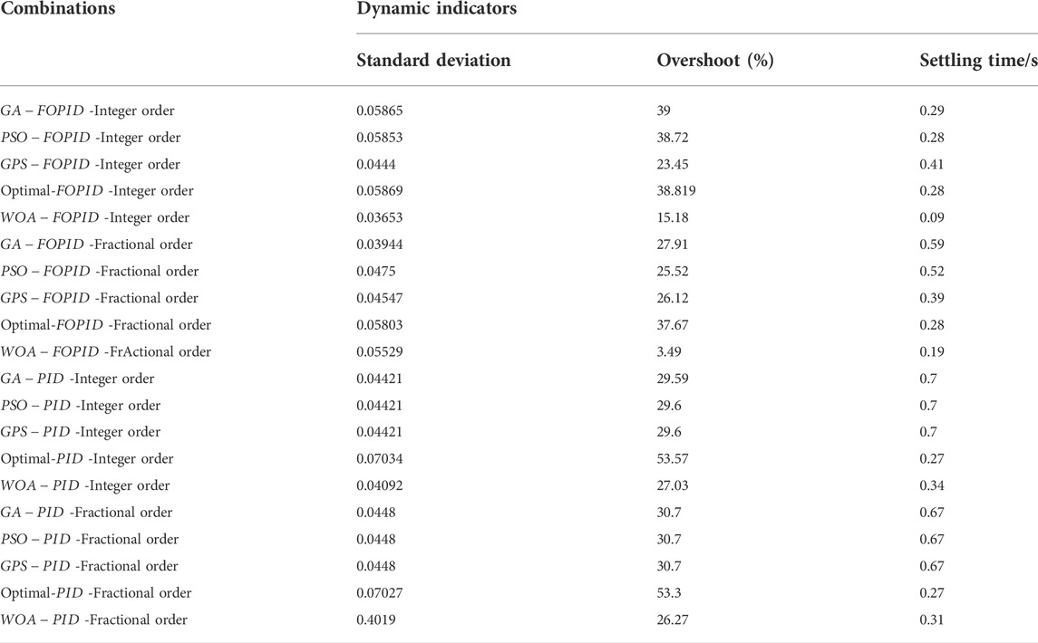
TABLE 3. Hydraulic motor’s parameter table.
Fractional order
Integer order
Respectively, four types of the intelligent control algorithm are used for parameter tuning of the
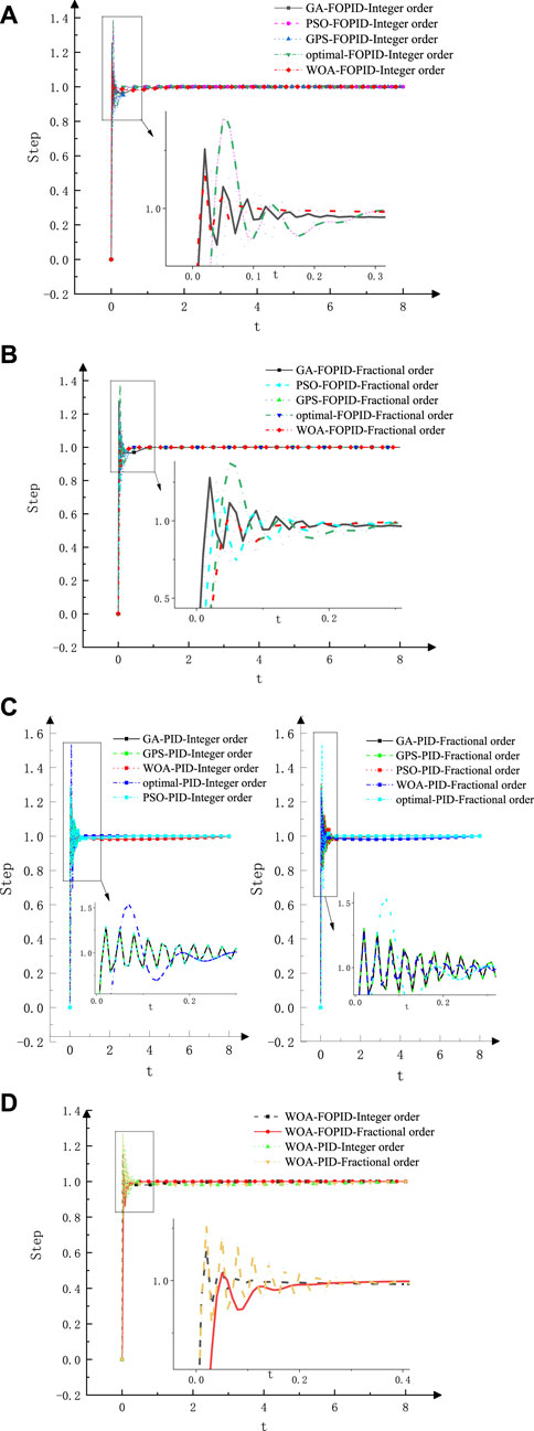
FIGURE 13. Control effect and step response of different combination strategies of the hydraulic motor. (A) The intelligent control algorithm for FOPID controller - integer order parameter setting diagram of controlled objects; (B) Parameter tuning diagram of FOPID controller-fractional controlled object by intelligent control algorithm; (C) Intelligent control algorithm PID controller - fractional integer order controlled object parameter setting diagram; (D) The intelligent control algorithm for FOPID controller - fractional integer order parameter setting graph of controlled objects.
On the whole, the
In response speed, adjustment time, and steady-state accuracy, the fractional order
(2) Mathematical modeling and simulation test of the hydraulic cylinder
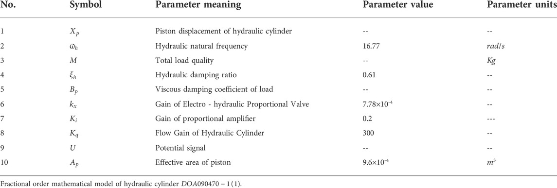
TABLE 4. Doa090470-1 (1) hydraulic cylinder parameter table.
The integer order mathematical model of the hydraulic cylinder
Integer order
Fractional order
Figure 14 and Table 5 show that the
(3) Mathematical modeling and simulation test of the hydraulic cylinder
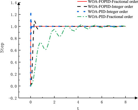
FIGURE 14.
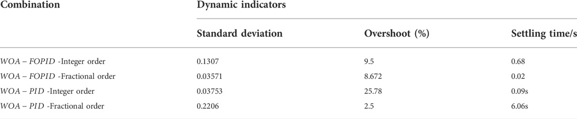
TABLE 5. Comparison of different combination strategies and control indexes of the
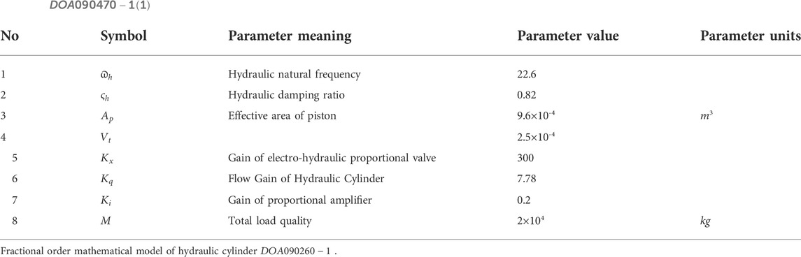
TABLE 6.
Integer order mathematical model of the hydraulic cylinder
Expression of the integer order PID controller [41–43]:
Expression of the fractional order
Figure 15 and Table 7 show that the
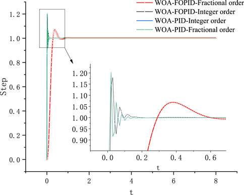
FIGURE 15. WOA-FOPID–fractional transfer function unit step diagram.
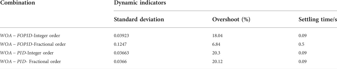
TABLE 7. Comparison of different combination strategies and control indicators.
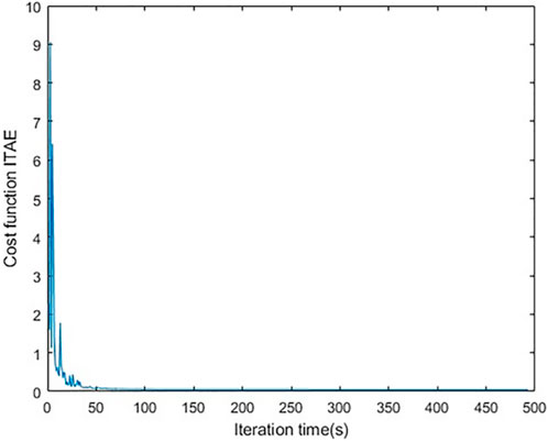
FIGURE 16. Cost function vs. iterations.
In order to verify the correctness and effectiveness of the control strategy in the manipulator control system of the mining roof bolter, the ground training and industrial tests were carried out in the underground roadway, as shown in Figure 17 and Figure 18. The test platform is the underground roadway, with a section height of 2.8–4 m, a width of 3.8–5.6 m, a maximum inclination of 20°, and a maximum drilling depth of 8.3 m. All of them are in a gas-free working environment. The test lasted a total of 9 days. In the first test, there were 14 anchor cable holes of 8.3 m, with a total of 116 m; 46.3 m anchor cable holes, 25 m in total; 124 m anchor cable holes, 48 m in total. In the second test, there were 6 anchor cable holes of 4 m, with a total of 24 m; 6.3 m anchor cable holes, totaling 37 m; 122.5 m anchor cable holes, 30 m in total.
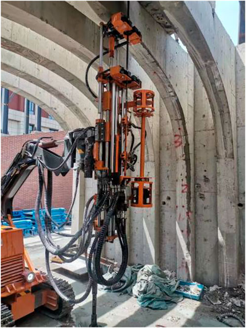
FIGURE 17. Ground experiment.
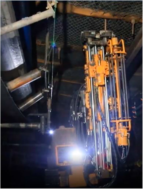
FIGURE 18. Downhole experiment.
The plan of an electric–control system is shown in Figure 19. The control system adopts a modular design, and each functional module runs independently without interference, so as to avoid whole equipment paralysis due to a single failure. The electric control system can be divided into five modules: main circuit unit, power unit, protection unit, signal conditioning isolation unit, and logic control unit. The block diagram of the control system module is shown in Figure 20.
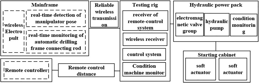
FIGURE 19. General scheme of an electric control system for the mining roof bolter.
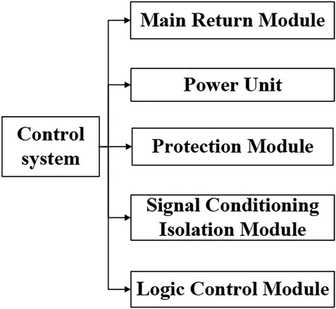
FIGURE 20. Composition of a control system module.
The main circuit module defines the main structure of the system, and the isolation switch is applied as the switch of the main circuit power supply of the electrical control box to control the oil pump circuit. In terms of control, a vacuum contactor is used in the oil pump circuit, and installed the resistance and capacitance absorption device, to absorb the high voltage generated by the motor in the vacuum contactor disconnection. There are three current transmitters on the cables of each circuit to complete the acquisition of analog quantity.
The power module is mainly composed of a main transformer and four air circuit breakers. The main transformer has three voltage ranges of the input tap: 1,250, 1,140, and 1,025 V. When the voltage is unstable in the coal mine, the transformer tap can be adjusted with the voltage change to ensure the stability of the output voltage, and then ensure the reliability of the control loop. A 24 V tap provides power for the lamp, 220 V for the contactor coil and power modules, and 127 V for the intrinsic safe power supply.
The short-circuit protection of the main circuit and the transformer circuit is realized by a circuit breaker. The motor over-current, overload, and phase break of each driving mechanism are prevented by the
The signal isolation module and the signal conversion module together constitute the signal conditioning isolation module. The isolation module realizes the conversion of (non) intrinsic safety signal, the input and output of various controllers and peripheral devices in the control system. The logic control unit is the core part of the entire electrical system, which can complete various protection functions and communication functions of the motor, and also realize the corresponding control functions: the actual running state of each motor is judged through the calculation and processing of the collection parameters of the system; if a fault occurs, appropriate trip instructions are issued according to the type of fault.
The control cabinet consists of a PLC controller module, HMI module, and a receiver module. Each working condition monitoring unit and input/output driving unit cooperate with each other to ensure the stable operation of each control function of the system. The hardware structure block diagram of the control system is shown in Figure 19. Digital input drive unit, analog input drive unit, and the antenna are the control center of the main input module, in which the knob and switch sensor units input information to the digital input drive unit; the handle potentiometer and analog sensor input information to the analog input drive unit; the remote transmitter inputs information to the receiver module through the antenna. The digital output drive unit comprises of a light, an indicator light, and a switching electro-magnetic valve; the analog output drive unit includes a variable pump and a proportional electro-magnetic valve. The hardware structural block diagram is shown in Figure 21. In addition, this study carried out the design of the power circuit and selection of the main components.
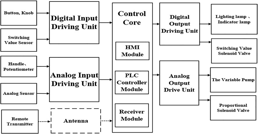
FIGURE 21. Hardware structure block diagram of the control system.
The software system is composed of an operation signal processor, video signal processor, fault information alarm software, equipment parameter setting software, data display and analysis software, data storage and analysis software, and signal output control software. Its structural block diagram is shown in Figure 22.
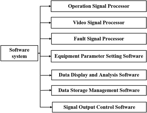
FIGURE 22. Control software and hardware structures’ block diagrams.
The electronic control system adopts the Siemens 200 series
A hydraulic anchor rod drill truck was carried out to the ground training drill from August 22 to August 23,2019, arrived to the coal mine on August 24, on August 25, in 11,505W, the transport lane carried out an industrial test, on August 26 implemented fire debugging, operation, and on August 28 began an advanced supporting anchor cable test behind the excavator. The periodic summary is as follows:
As of September 9, 38 holes were drilled, among which 35 were anchored, 3 holes were drilled during the test, respectively 3.0, 5.0, and 5.5 m, without anchoring.
With a 6.3 m grouting anchor, it takes about 4 min on average to move forward to adjust the position of the drill truck, 14 min on average to drill, 8 min on average to withdraw the drill, 4 min on average to install the anchor cable, and 30 min on average in total. Fourteen representative boreholes in the early experimental period were selected for analysis, as follows in Table 8.
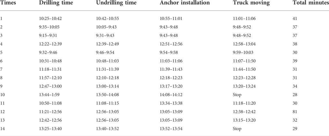
TABLE 8. Test record of the anchor rod drill truck.
According to the experimental conclusions:
(1) After the control system design is completed, it is debugged and applied on the roof bolter. The control system realizes the remote pump station start–stop control, hydraulic cylinder position control, and meets the requirements of the process operation. The experiment proves that the
(2) The automatic support system of the manipulator of the mining roof bolter breaks through the technology of automatic transportation of anchoring agents and the technology of transportation bolts and cables, and realizes a real automatic support working line without man-made interference. The manipulator can automatically drill bolt holes, cable holes, cut top holes, coal powder detection holes, water injection holes, and 360° all-round drilling. In the later stage, the automatic support working line can be combined with the automatic tunneling cutting, and the unmanned driving face can be built.
To find whether the mining roof bolter can realize precise hole positioning, in a complex environment, this article uses
(1) From the model built from
(2) The effectiveness of the
The original contributions presented in the study are included in the article/supplementary material; further inquiries can be directed to the corresponding author.
Writing the original draft, ZJ; Funding acquisition, ZJ; Data curation, WY, CL, WN, BY, and WC. All authors have read and agreed to the published version of the manuscript.
The author wishes to thank the Youth fund of National Natural Science Foundation of China (No. 52104165), Free exploration general fund of Shanxi Provincial Department of science and technology (No: 20210302123123), State Key Laboratory of robotics and systems (No.SKLRS-2021-KF-16).
ZJ was employed by China Coal Science and Industry Group Co., Ltd. and Ningxia Tiandi Benniu Industrial Group Co., Ltd. CL, WN, and BY were employed by China Coal Science and Industry Group Co., Ltd. The remaining authors declare that the research was conducted in the absence of any commercial or financial relationships that could be construed as a potential conflict of interest.
All claims expressed in this article are solely those of the authors and do not necessarily represent those of their affiliated organizations, or those of the publisher, the editors, and the reviewers. Any product that may be evaluated in this article, or claim that may be made by its manufacturer, is not guaranteed or endorsed by the publisher.
Al-Saggaf, U., Mansouri, R., Bettayeb, M., Mehedi, I. M., and Munawar, K. (2020). Robustness improvement of the fractional order LADRC scheme for integer high order system, IEEE Transactions on Industrial Electronics (ISSN:0278-0046), 99. IEEE, 1. doi:10.1109/TIE.2020.3016258
Author Anonymous State Administration of coal mine safety Key R & D catalogue of coal mine robot [Z] Announcement No. 1, 2019.
Bushnaq, S., Saeed, T., Torres, D. F. M., and Zeb, A. (2021). Control of COVID-19 dynamics through a fractional-order model. Alexandria Eng. J., 3587–4359. (ISSN.1110-0168). doi:10.1016/j.aej.2021.02.022
Caponetto, R., Machado, J. T., Murgano, E., and Xibilia, M. G. (2019). Model order reduction: A comparison between integer and non-integer order systems approaches. Entropy 9, 876. (ISSN:1099-4300) 21. doi:10.3390/e21090876
Chen, Wei, Yu, Y, and Zhao, X (2013). Position control strategy and experimental research of 2R underactuated planar flexible manipulators. J. Mech. Eng. 49 (23), 80. (ISSN:1823-5514). doi:10.3901/jme.2013.23.080
Cuong, H. M., Quoc Dong, H., Trieu, P. V., and Tuan, L. A. (2020). Adaptive fractional-order terminal sliding mode control of rubber-tired gantry cranes with uncertainties and unknown disturbances. Mech. Syst. Signal Process. 154, 107601. (ISSN:0888-3270). doi:10.1016/j.ymssp.2020.107601
Dalir, M., and Bigdeli, N. (2020). The design of a new hybrid controller for fractional-order uncertain chaotic systems with unknown time-varying delays. Appl. Soft Comput. 87, 106000. doi:10.1016/j.asoc.2019.106000
Dasgupta, K., Mukherjee, A., and Maiti, R. (1996). Modeling and dynamics of epitrochoid generated orbital rotary piston lsht hydraulic motor: A bondgraph approach. J. Manuf. Sci. Eng. 118, 415–421. doi:10.1115/1.2831046
Dimeas, I., Petras, I., and Psychalinos, C. (2017). New analog implementation technique for fractional-order controller: A dc motor control. AEU - Int. J. Electron. Commun. 78, 192–200. doi:10.1016/j.aeue.2017.03.010
Ding, Y., Xu, J., Cao, J., and Zhang, D. (2017). Mathematical modeling about nonlinear delayed hydraulic cylinder system and its analysis on dynamical behaviors. Discrete Cont. Dyn. S 10 (5), 943–958. doi:10.3934/dcdss.2017049
Dingyu, P. X. (2020). Lecture hall Volume 4 MATLAB optimization calculation [M. Beijing: Tsinghua University Press.
Do, T. C., Trần, T. D., Dinh, T. Q., Ahn, K. K., et al. (2020). Tracking control for an electro-hydraulic rotary actuator using fractional order fuzzy PID controller. Electronics, 926. (ISSN:2079-9292) 9.6. doi:10.3390/electronics9060926
Feng, G.-L., Chen, B.-R., Xiao, Y.-X., Jiang, Q., Li, P.-X., Zheng, H., et al. (2022). Microseismic characteristics of rockburst development in deep tbm tunnels with alternating soft-hard strata and application to rockburst warning: A case study of the neelum-jhelum hydropower project. Tunn. Undergr. Space Technol. 122, 104398. doi:10.1016/j.tust.2022.104398
Feng, G.-L., Feng, X.-T., Chen, B.-r., Xiao, Y.-X., and Yu, Y. (2015). A microseismic method for dynamic warning of rockburst development processes in tunnels. Rock Mech. Rock Eng. 48 (5), 2061–2076. doi:10.1007/s00603-014-0689-3
Ge, S., and Hu, P. W (2020). Coal mine robot system and key technology. J. coal 45 (01), 455–463. (ISSN: 0166-5162).
Higazy, M. (2020). Novel fractional order SIDARTHE mathematical model of COVID-19 pandemic. Chaos, Solit. Fractals 138, 110007. ISSN:0960-0779. doi:10.1016/j.chaos.2020.110007
Huang, S., Wang, J., Huang, C., Zhou, L., Xiong, L., Liu, J., et al. (2022). A fixed-time fractional-order sliding mode control strategy for power quality enhancement of PMSG wind turbine. Int. J. Electr. Power & Energy Syst. 134, 107354. (ISSN:0142-0615). doi:10.1016/j.ijepes.2021.107354
Jing, X, and pan, X. W (2018). Fuzzy PID attitude control of pesticide spraying four axis aircraft. J. drainage irrigation Mech. Eng. 36 (5), 7. doi:10.3969/j.issn.1674.8530.17.0187
Kang, H. P. (2007). Wang Jinhua Roadway bolt support theory and complete set of technology [M]. Beijing: Coal Industry Press.
Li, F., Hu, J., and Zhang, D. R. (2019). Development and application status and trend of coal mine robot. China coal.. 045 (007), 28–32. doi:10.19880/j.cnki.ccm.2019.07.005
Li, R., Cao, J., Xue, C., and Manivannan, R. (2021). Quasi-stability and quasi-synchronization control of quaternion-valued fractional-order discrete-time memristive neural networks. Appl. Math. Comput. 395, 125851. (ISSN:0096-3003). doi:10.1016/j.amc.2020.125851
Li, Z, and Xing, l (2007). Submarine robot automatic tracking scheduled mining path control. J. Mech. Eng. 43 (1), 6. doi:10.3321/j.issn:0577-6686.2007.01.025
Liu, F., Cao, W., and Zhang, J. (2021). Scientific and technological innovation progress of China's coal industry and the development direction of the 14th five year plan. J. coal 46 (1), 1–15. doi:10.13225/j.cnki.jccs.2021.0042
Long, Z-M., Guan, B-J., Chen, S-Y., Chen, G-J., and Guo, S-Q. (2018). “Modeling and simulation of hydraulic motor tracking servo motor driving load,” in ICSGEA, 118–121. doi:10.1109/icsgea.2018.00037
Luo, Y, Du, L, Zhou, S, and Luo, K (2021). Simulation research on electro-hydraulic proportional position control system of blanking based on fuzzy PID. Mach. tool hydraulic. doi:10.3969/j.issn.1001-3881.2021.22.030
Ma, F. Research on Modeling and control of single-phase PWM rectifier based on fractional order. Zhengzhou: Henan University of technology.
Maâmar, B., and Rachid, M. (2014). IMC-PID-fractional-order-filter controllers design for integer order systems. ISA Trans. 53, 1620–1628. 0019-0578) 53. doi:10.1016/j.isatra.2014.05.007
Maiti, D., Biswas, S., and Konar, A. (2008). Design of a fractional order PID controller using particle swarm optimization technique. Int. J. Adv. Manuf. Technol., 521–531. ISSN:0268-3768) 58.5-8.
Musarrat, M. N., and Fekih, A. (2021). A fractional order sliding mode control-based topology to improve the transient stability of wind energy systems. Int. J. Electr. Power & Energy Syst. 133, 107306. (ISSN:0142-0615). doi:10.1016/j.ijepes.2021.107306
Nguyen, D., Bao, D. L., and Choi, S-B. (2021). Smart dampers-based vibration control–Part 2: Fractional-order sliding control for vehicle suspension system. Mech. Syst. Signal Process. 148, 107145. (ISSN:0888-3270). doi:10.1016/j.ymssp.2020.107145
Podlubny, I. (1999). Fractional-order systems and PI/sup/spl lambda//D/sup/spl mu//-controllers. IEEE Trans. Autom. Contr. 44, 208–214. doi:10.1109/9.739144
Ren, H. P., Fan, J. T., and Kaynak, O. (2019). “Optimal design of a fractional-order proportional-integer-differential controller for a pneumatic position servo system,” in IEEE Transactions on Industrial Electronics (IEEE). (ISSN:0278-0046). doi:10.1109/TIE.2018.2870412
Semmari, H., Mauran, S., and Stitou, D. (2017). Experimental validation of an analytical model of hydraulic motor operating under variable electrical loads and pressure heads. Appl. Energy 206, 1309–1320. (ISSN:0306-2619). doi:10.1016/j.apenergy.2017.10.010
Sheng, Y., Bai, W., and Xie, Y. (2021). Fractional-order $$PI^{\\lambda D$$ sliding mode control for hypersonic vehicles with neural network disturbance compensator. Nonlinear Dyn. 103 (3). (ISSN:0924-090X). doi:10.1007/s11071-020-06046-y
Tolba, M. F., AboAlNaga, B. D. M., Said, L. A., Madian, A. H., and Radwan, A. G. (2018). Fractional order integrator/differentiator: FPGA implementation and FOPID controller application. AEU - Int. J. Electron. Commun. 98, 220–229. doi:10.1016/j.aeue.2018.10.007
Wachholz, L. C., Valdiero, A. C., and Rasia, L. A. . "Mathematical modeling of a hydraulic motor operated and controlled by proportional valve." COB2019 2019. doi:10.26678/ABCM.COBEM2019.COB2019-2272
Wang, G., Liu, F., Pang, Y., Ren, H., and Ma, Y. (2019). Coal mine intelligence -- the core technical support for the high-quality development of coal industry. J. coal 44 (02), 349–357. (ISSN: 0166-5162).
Wang, G., Wang, H., and Ren, H. (2018). Scenario objectives and development path of smart coal mine 2025. J. coal 43 (02), 295–305. doi:10.13225/j.cnki.jccs.2018.0152
Wang, H., Wang, J., and Zhang, X. (2020). Theory and technology of integrated and efficient excavation with excavation and anchor. J. coal 45 (6), 2021–2030. (ISSN: 0166-5162).
Wu, X., and Huang, Y. (2021). Adaptive fractional-order non-singular terminal sliding mode control based on fuzzy wavelet neural networks for omnidirectional mobile robot manipulator - ScienceDirect. ISA Trans. 121, 258–267. doi:10.1016/j.isatra.2021.03.035
Yang, Y., Zhao, D-C., Feng, G-L., Geng, D-X., and Guo, H-S. (2022). Energy evolution and acoustic emission characteristics of uniaxial compression failure of anchored layered sandstone. Front. Earth Sci. 10, 841598. doi:10.3389/feart.2022.841598
Yin, C., Chen, Y. Q., and Zhong, S. M. (2014). Fractional-order sliding mode based extremum seeking control of a class of nonlinear systems. Automatica 50 (3), 3173–3181. doi:10.1016/j.automatica.2014.10.027
Yin, C., Chen, Y. Q., and Zhong, S. M. (2014). Fractional-order sliding mode based extremum seeking control of a class of nonlinear systems. Automatica 50 (12), 3173–3181. (ISSN:0005-1098). doi:10.1016/j.automatica.2014.10.027
Zamani, M., Karimi-Ghartemani, M., Sadati, N., and Parniani, M. (2009). Design of a fractional order PID controller for an AVR using particle swarm optimization. Control Eng. Pract. 17 (12), 1380–1387. (ISSN:0967-0661). doi:10.1016/j.conengprac.2009.07.005
Zhan, C, Deng, J, and Chen, K (2015). Research on low friction high frequency response variable clearance sealed hydraulic cylinder. J. Mech. Eng. 51 (24), 7–5. doi:10.3901/JME.2015.24.161
Zhang, J, and Li, Y (2019). Kinematic error analysis of mechanical arm of roof bolter with uncertain parameters. J. coal 44 (10), 3223–3232. (ISSN: 0166-5162).
Zhang, J, Zhang, Q. G., and Zhifu, U (2019). Dynamic uncertainty analysis of mechanical arm of mine roof bolter. J. coal 44 (S1), 351–360. (ISSN: 0166-5162).
Keywords: manipulator, fractional FOPID, whale algorithm, motion control, anchor drilling robot
Citation: Jun Z, Yiliang W, Liming C, Ning W, Yuepin B and Chaofan W (2022) Workspace analysis and motion control strategy of robotic mine anchor drilling truck manipulator based on the WOA-FOPID algorithm. Front. Earth Sci. 10:954547. doi: 10.3389/feart.2022.954547
Received: 27 May 2022; Accepted: 27 June 2022;
Published: 04 August 2022.
Edited by:
Guang-Liang Feng, Institute of Rock and Soil Mechanics (CAS), ChinaReviewed by:
Liu Liu, Institute of Rock and Soil Mechanics (CAS), ChinaCopyright © 2022 Jun, Yiliang, Liming, Ning, Yuepin and Chaofan. This is an open-access article distributed under the terms of the Creative Commons Attribution License (CC BY). The use, distribution or reproduction in other forums is permitted, provided the original author(s) and the copyright owner(s) are credited and that the original publication in this journal is cited, in accordance with accepted academic practice. No use, distribution or reproduction is permitted which does not comply with these terms.
*Correspondence: Zhang Jun, emhhbmdqdW4wN0B0eXV0LmVkdS5jbg==
Disclaimer: All claims expressed in this article are solely those of the authors and do not necessarily represent those of their affiliated organizations, or those of the publisher, the editors and the reviewers. Any product that may be evaluated in this article or claim that may be made by its manufacturer is not guaranteed or endorsed by the publisher.
Research integrity at Frontiers
Learn more about the work of our research integrity team to safeguard the quality of each article we publish.