 Qingzhi Chen
 Yuanming Liu
 Wei Wang2
95% of researchers rate our articles as excellent or good
Learn more about the work of our research integrity team to safeguard the quality of each article we publish.
Find out more
ORIGINAL RESEARCH article
Front. Earth Sci. , 18 July 2022
Sec. Geohazards and Georisks
Volume 10 - 2022 | https://doi.org/10.3389/feart.2022.950648
This article is part of the Research Topic Advances in Modeling, Assessment, and Prevention of Geotechnical and Geological Disasters View all 44 articles
In this study, cement mortar was used to make specimens containing groups of parallel joints with different inclination angles to simulate natural rock mass, and the specimens were subjected to shear tests under different normal stresses. By analyzing the crack propagation path, failure modes, and strength characteristics of these rock specimens, the effects of normal stress and joint inclination angles on the strength and failure characteristics of this type of rock mass were studied. The following conclusions are drawn: 1) when the inclination angles of the joints are 0° and 15°, the changing of the normal stress did not affect the failure mode of the rock mass. The rock mass was mainly in the mode of shear failure, and the increase in the normal stress only increased the spalling area of the rock mass. 2) When the inclination angles of the joints are 30°, 45°, and 60°, with the increasing of the normal stress, the number of those approximately parallel cracks in the specimens increased, the friction marks caused by shearing increased, and the failure mode of the rock mass changed from tension failure to tension–shear composite failure. 3) Under different joint inclination angles, the propagation and penetration paths of cracks generated in the rock mass and the damage mode of the rock mass were different. With an increase in the joint inclination angles, the damage mode of the rock mass gradually changes from shear damage to tensile–shear composite damage and the α and β angles between the through cracks and the vertical direction on the left and right sides of the specimens tended to decrease. 4) The shear resistance of the rock mass was affected by the inclination angle of the joints and the normal pressure. The shear resistance of rock mass was improved due to the increasing of normal stress. Within a certain range, with the increasing of the inclination angles of the joint, the shear resistance of the rock mass tended to decrease first and then to increase.
Jointed rock mass is a very complex area of engineering closely related to underground engineering and slope engineering (Zhu et al., 2019; Xia et al., 2022). The existence of joints makes the fracture forms of rock mass more diverse and complex, and is also the most important factor in reducing the overall strength of rock mass (Shaunik and Singh, 2020; Tian et al., 2020; Guo et al., 2022). Under loaded conditions, the entire rock mass is more likely to rupture or even collapse due to the presence of joints (Liu et al., 2013; Ban et al., 2021; Tian et al., 2020). Therefore, the damage and strength characteristics of jointed rock mass have become important factors affecting the stability and safety of underground cavern excavation and slope engineering, giving them great research significance (Li et al., 2019; Dong et al., 2021; He et al., 2018). At present, domestic and foreign scholars have conducted a lot of research on the mechanical and strength characteristics of jointed rock mass, which also provides more reference and theoretical support for this research (Cao et al., 2020; Yang S.-Q. et al., 2019). In physical tests on rock masses with joints, the influence of one or two smooth joints on the strength of the rock mass has been studied (Huang and Yang, 2018; Niu et al., 2019; Wang et al., 2019). However, it is not common to study the influence of multiple parallel grouped joints with different inclination angles on the strength characteristics of rock mass and the form of crack propagation (Hu et al., 2022). It is worth noting that it is relatively common for multiple inclined joints to appear in groups in real rock masses. For example, in the Tongzi tunnel of the seventh contract section of the Chongqing–Zunyi section (in Guizhou) of the Lanzhou–Haikou National Expressway in China, the surrounding rocks are mainly grades IV and V, and the geological structures such as joints in the surrounding rocks are well developed. There are abundant parallel groups of joint planes with different inclination angles, as shown in Figure 1. In addition, in the natural environment, the stress states of rock mass are complex and diverse. The stability of the rock mass where a project is located will directly affect the quality and safety of the project (Yang Y. et al., 2019). For example, the rock and soil mass within a certain range around the roadway or the tunnel excavation face is also known as the surrounding rock. The mechanical properties of the surrounding rock are its resistance to deformation and failure; that is, its compressive, tensile, and shear capacity. These elements obviously affect the overall safety and stability of the tunnel (Xu 1993). Therefore, it is of great theoretical and practical significance to study the mechanical and strength characteristics, the failure modes, and the path of crack propagation of rock mass with abundant parallel grouped joints with different inclination angles as this has very important theory and engineering practice significance (Chen et al., 2020; Wang 2020).
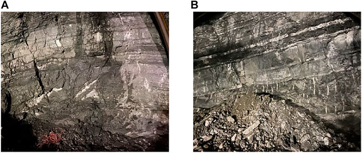
FIGURE 1. Joints in the surrounding rock of the Tongzi tunnel. (A) Scenario 1. (B) Scenario 2.
Due to the brittleness of rock mass, it is difficult to obtain specimens, so the method of making rock-like material models with gypsum or cement mortar to study the mechanical and strength properties of rock mass has been widely used (Fan et al., 2021a; Lin et al., 2021a; Fan et al., 2021b; Lin et al., 2021b). For instance, Zhang et al. (2012) prepared 12 kinds of samples with multiple cross cracks using cement mortar and conducted uniaxial compression test research. Their study showed that the number and form of cracks have a significant impact on the strength characteristics of rock mass, and the existence of crossed multiple cracks affects the peak strength, the size of the crack initiation stress of the rock, and the form of the failure surface of the specimens. Zhou et al. (2018) performed uniaxial compression tests on samples of rock-like materials with three defects. They used three-dimensional digital imaging correlation technology to capture the displacement field and strain field of the surface of the samples in real time and studied the effect of the brittleness of rock-like materials on crack initiation, propagation, and coalescence behavior. Cao et al. (2018) selected the jointed rock mass specimens made of rock-like materials containing a single cavity to study the effect of the interaction between the opening and the parallel grouped joints on the crack propagation and the penetration of the rock mass around the opening by combining physical tests and numerical simulation tests. At the same time, the influence of joint spacing and inclination angle on mechanical parameters such as uniaxial compressive strength and elastic modulus of specimens was studied. Their results showed that a circular opening has a great influence on the failure mode of the non-through jointed rock mass, and the specimens in this test eventually showed four different failure modes. Xu et al. (2021) combined acoustic emission and digital scattering techniques to investigate the effect of printed layer thickness on the physical and mechanical properties of sand powder 3D printed rock-like specimens.
In view of the foregoing, the geology of Tongzi tunnel is complex, with abundant structural surfaces and complicated lithology, and groups of parallel joints are very common in the rock surrounding the tunnel. The study of the effect of these parallel joints on the crack extension penetration, damage form, and strength characteristics of the tunnel rock can provide theoretical support for the excavation, support, and maintenance of the Tongzi tunnel. Thus, the study is of great practical importance to the overall stability and safety of the Tongzi tunnel project. In view of the foregoing, the geology of the Tongzi tunnel is complex, with abundant structural surfaces and complicated lithology, and groups of parallel joints are very common in the rock surrounding the tunnel. The study of the effect of these parallel joints on the crack extension penetration, damage form, and strength characteristics of the tunnel rock can provide theoretical support for the excavation, support, and maintenance of the Tongzi tunnel. Thus, this study is of great practical importance to the overall stability and safety of the Tongzi tunnel project. At this stage, the relevant research mainly focuses on the influence of single, double, or cross joints on the mechanical properties of the tunnel rock mass under uniaxial compression experimental conditions. The number of joints contained in the studied rock masses is relatively small, the force conditions of the rock mass are largely single, and the influence of parallel groups of joints on the mechanical properties of the rock mass under compression–shear composite conditions is seldom considered. Therefore, this article studies the effect of parallel grouped joints on the mechanical properties of rock masses, taking into account the real state of the rock surrounding the Tongzi tunnel and the force characteristics of the rock mass, which can not only complement the study of the mechanical properties of rock masses but can also provide theoretical support for the safe operation of the Tongzi tunnel. Scholars’ research on indoor experiments and numerical model analysis of specimens of raw rock or rock-like materials can provide theoretical and methodological support for the progress of this study (Yang et al., 2020; Zheng et al., 2019; Xia et al., 2019, 2020), and the validation of the method of using rock-like materials instead of raw rock materials for subsequent studies on mechanical properties makes this study practical and feasible (Zheng et al., 2022). Thus, in this study, the crack extension penetration paths, rock damage forms, and strength properties of rock mass specimens containing parallel groups of joints will be investigated under compression–shear composite conditions using a cement mortar casting rock-like material model with the Tongzi tunnel as the research site.
Through the understanding of actual engineering projects and the research of the aforementioned scholars, we found that the influence of joints on the mechanical properties of rock mass is very significant. In order to analyze the influence of joint inclination angle on rock mechanics and strength characteristics, this study refers to the mix ratio of rock-like materials used in related research (Bai et al., 1999; Gao et al., 2019; Liu et al., 2016; Pu et al., 2010). A mass mix ratio of water:cement:sand = 1:2:3 was used in this research to make rock mass specimens with joints with different inclination angles and with sizes of 200 mm×200 mm×200 mm. The symbol “θ” is used to represent the joint inclination angles of the rock specimens, which is the angle generated by the intersection of the joint and the shear plane (as shown in Figure 2). The “θ” value includes five gradients of 0°, 15°, 30°, 45°, and 60°, as shown in Figure 3.
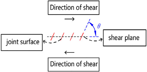
FIGURE 2. Schematic diagram of joint inclination.
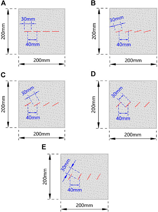
FIGURE 3. Schematic diagram of a rock specimen with parallel grouped joints (A) Inclination angle is 0°.(B) Inclination angle is 15°.(C) Inclination angle is 30°.(D) Inclination angle is 45°.(E) Inclination angle is 60°.
The specific procedures for the preparation of the specimens are described as follows:
Step 1. Adequate material was weighed and mixed according to the mass ratio of sand:cement:water = 3:2:1, and the loss factor was taken into account.
Step 2. mold release agent was applied evenly on the inside of the mold.
Step 3. The mixture was poured into the mold and vibrated, and the upper surface was smoothed after the pouring was completed.
Step 4. Steel plates with a thickness of 0.2 mm were inserted into the cement mortar of the mold at the specified position as shown in Figure 4. The steel sheets were pulled out 6–8 h after the insertion, and the structural planes simulated the joint planes in the rock mass material.
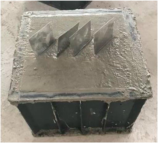
FIGURE 4. Specimen after joint pre burial.
Step 5. After 18–24 h, when the specimens reached the initial setting strength, the mold was removed and maintained for 28 days to obtain rock specimens containing joints with different inclination angles, as shown in Figure 5.The mechanical tests in this study were carried out using the rock and concrete mechanical test system shown in Figure 6, that is, the RMT-301 system. This instrument has a high degree of accuracy and automation, and its test procedure can be controlled manually. The user can control the end time of the test by presetting the maximum normal stress and the maximum shear displacement.
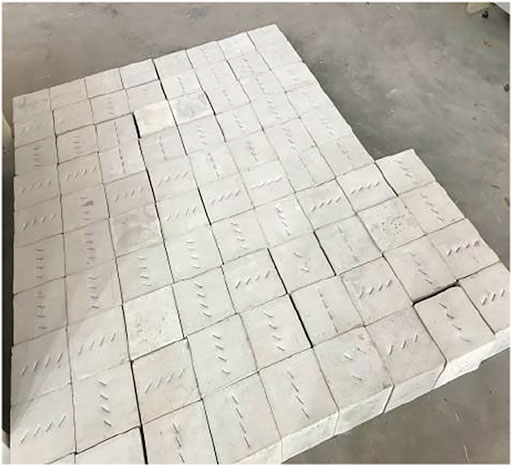
FIGURE 5. Finished models.
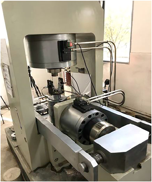
FIGURE 6. RMT-301 system.
After the preparation of cubic specimens without seams with a side length of 200 mm was completed, the specimens were drilled, sampled, ground, and numbered. Additionally, the obtained specimens were subjected to a triaxial compression test and a Brazilian splitting test (the process is shown in Figure 7) to determine whether the cement mortar with the mass ratio of water:cement:sand = 1:2:3 can be used as a material to simulate the natural rock mass for the model.
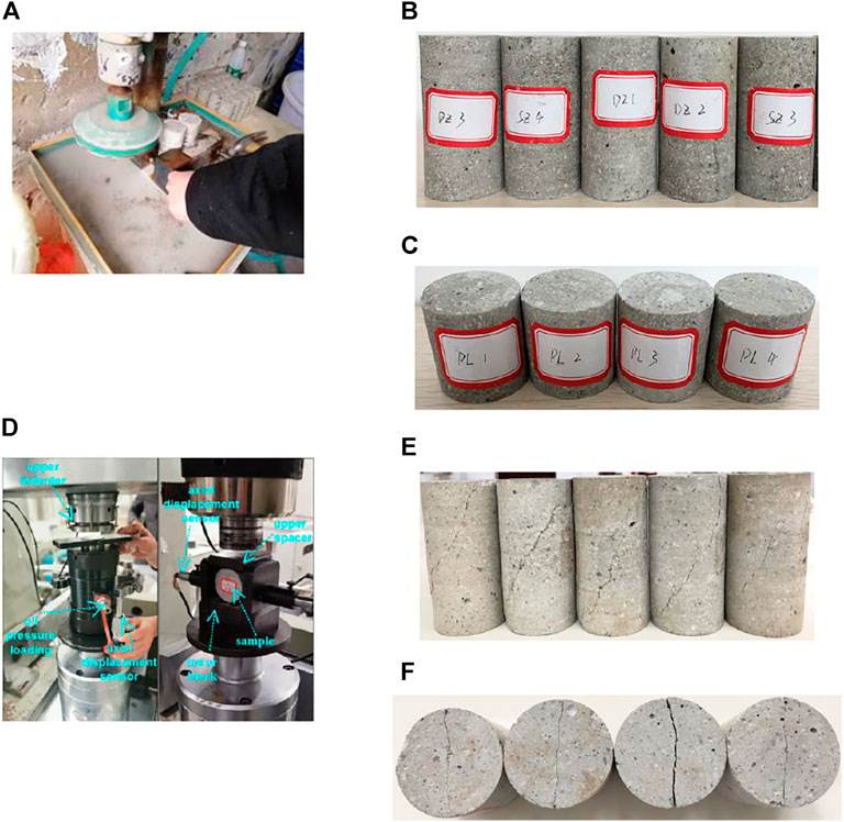
FIGURE 7. Mechanical experiment process for parameter calibration. (A) Producing specimens. (B) Specimens for triaxial experiments. (C) Specimens for Brazilian cleavage tests. (D) Process of the experiment. (E) Specimens after triaxial test. (F) Specimens after Brazilian splitting test.
Since the friction angle and cohesion of the rock specimens cannot be obtained directly from the data calculation system of the instrument, they need to be obtained by calculation. Therefore, in this study, the peak normal stress σ1 of each specimen was used as the vertical coordinate and the confining pressure σ3 was used as the horizontal coordinate, and then the optimal relationship curve of the data points of each specimen was plotted by the graphical method. Finally, the cohesion and internal friction angle of the rock samples were calculated according to the following equations (Zhou 1990):
In the formula:
C is the internal friction force of the rock (MPa).
m is the slope of the optimal relationship curve.
After calculation, the basic mechanical parameters such as cohesion and internal friction angle of the rock-like material specimens used in this study are shown in Table 1, and the mechanical parameters of several common natural rocks are also listed in Table 1 (Li and Wu 1996). Additionally, different types of rock-like materials used in the studies of Bai et al. (1999), Gao et al. (2019), Liu et al. (2016), and Pu et al. (2010) were referenced, and the mechanical parameters of these rock-like materials are listed in Table 2. The mechanical parameters of these common natural rocks and rock-like materials from the references are compared with those of the rock-like materials used in this study.
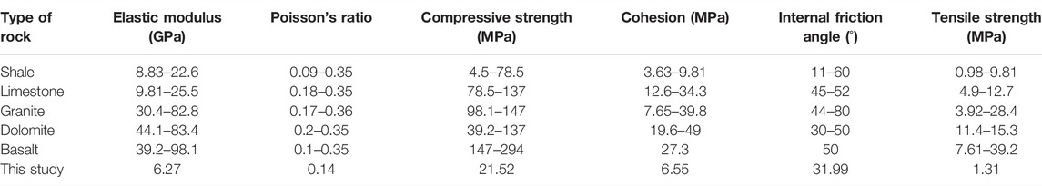
TABLE 1. Basic mechanical parameters of several common rocks.
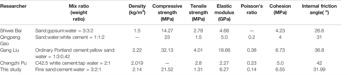
TABLE 2. Mixing ratio of rock-like materials and their mechanical parameters.
As demonstrated in Table 1, the parameters of shale range as follows: modulus of elasticity 8.83–22 GPa, Poisson’s ratio 0.09–0.3, compressive strength 4.5–78.5 MPa, cohesion 3.63–9.8 MPa, angle of internal friction 11–60°, and tensile strength 0.98–9.8 MPa. As demonstrated in Table 2, the parameters of rock-like materials are as follows: density 1.5–2.22 kg/m3, compressive strength 12–59.77 MPa, tensile strength 1.12–4.01 MPa, modulus of elasticity 1.5–16.03 GPa, Poisson’s ratio 0.15–0.38, cohesion 0.25–14.35 MPa, and angle of internal friction 26.6–42°. The parameters of this study are as follows: density 2.14 kg/m3, elastic modulus 6.27 GPa, Poisson’s ratio 0.14, compressive strength 21.52 MPa, cohesive force 6.55 MPa, internal friction angle 31.99°, and tensile strength 1.31 MPa. Therefore, after the numerical comparison, it can be found that the mechanical parameters of rock-like materials in this study are in the same order of magnitude as those of common rock materials and are in better agreement with the reference range of mechanical parameters of shale. Additionally, the parameters of the rock-like materials used in this study are in the range of variation of the mechanical parameters of the rock-like materials used in the aforementioned related studies. In summary, the model developed in this study with cement mortar with the mass-combination ratio of water:cement:sand = 1:2:3 can be used to simulate natural rock masses. Therefore, the following experimental results obtained from the compression–shear composite tests on the rock-like material model containing groups of flat jointed formations in this study can be used to summarize the effects of joint structures in natural rock masses on the strength properties and damage forms of these rock masses.
After calibrating the parameters, direct shear tests were performed on specimens containing parallel and grouped joints with different inclination angles under different normal stresses. The loading is shown in Figure 8. The rock specimens as shown in Figure 3 were subjected to direct shear tests at normal stresses of 0.5, 1.0, 1.5, 2.0, and 3.0 MPa. In the direct shear test, the normal stress was applied first, and when the normal stress was close to the ideal value, the horizontal load was applied. Additionally, the horizontal load was applied by controlling the horizontal displacement rate of 0.005 mm/s. When the predetermined horizontal shear displacement was reached, the instrument was manually controlled to stop shearing.
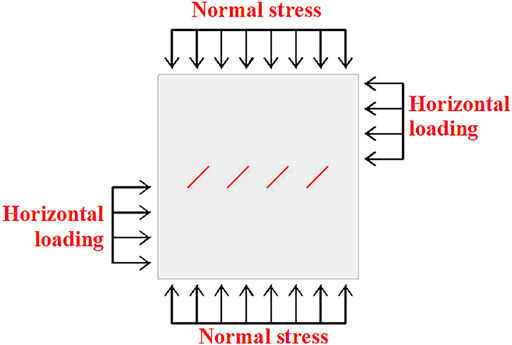
FIGURE 8. Schematic representation of the loading method.
In previous studies, cracks were classified into two categories according to the causes of rock cracks: tensile cracks and shear cracks. The damage modes of the specimens were classified into tensile and shear damage according to the type of the main cracks that led to the damage of the specimens (Chen, 2019; Mei et al., 2019; Schwartzkopff et al., 2020). It was shown that when tensile damage occurred, the surface of the specimens was clean, with traces of tensile cracks clearly visible and no obvious fragmentation. However, when shear damage occurred, the surface of the specimen had some flakes or spalling, and there were obvious scratches on the upper and lower shear surfaces of the specimen after fracture, and the surface of the newly generated cracks was rough. (Song et al., 2020; Ma et al., 2021). When shear tests are performed at different normal stresses, the rock masses may undergo only tensile damage or only shear damage, or combined tensile and shear damage. In this study, the rock masses with five types of inclined joints were subjected to direct shear tests at different normal stresses, and the final damage morphology statistics of the specimens are shown in Table 3.
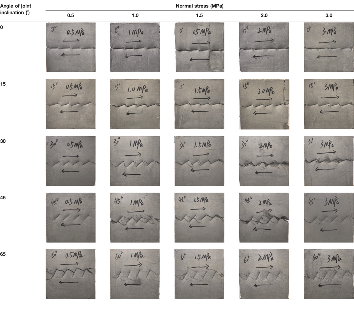
TABLE 3. Statistical table of the failure form of the samples.
The damage states of the aforementioned specimens are divided into five groups according to the inclination angle of the joints for analysis, as shown in Figures 9–13. Among them, Figures A–E show the states of the specimens after shear tests under different normal stresses, and Figure F shows the simplified form of the rock damage and the penetration path of the cracks.
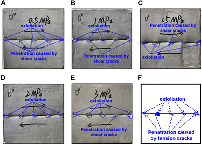
FIGURE 9. Failure form and crack penetration path of jointed rock mass with inclination angle of 0°. (A) Normal stress is 0.5 MPa. (B) Normal stress is 1 MPa. (C) Normal stress is 1.5 MPa. (D) Normal stress is 2 MPa. (E) Normal stress is 3 MPa. (F) Sketch of the rock damage state and the penetration path of the fracture.
Figure 9 shows that after the direct shear test of a rock mass containing parallel, grouped, smooth joints with an inclination angle of 0° under the fifth-order normal stress, the fracture surface of the rock mass is flushed with the face of the prefabricated joints. There may be some microelements inside the specimens that reach the tensile strength, but because their small number does not form a clear through face, no clear through tensile crack is formed at the end of the prefabricated joints. In addition, it is obvious from Figure 9 that cracks with debris remaining in the middle or block spalling were produced on the surface of the specimens because of the force applied, and the surface of these cracks produced after the destruction of the specimens was uneven, which was obviously caused by friction due to the shearing action. Therefore, it can be found that when shear tests were performed on rock masses containing groups of smooth joints with an inclination angle of 0°, the change in normal stress did not have a significant effect on the failure mode and penetration path of the rock masses and only resulted in a difference in the area of spalled blocks. The rock masses all eventually underwent shear damage because they were mainly subjected to shear action, and the rock masses eventually produced shear damage surfaces that were flushed with the original joint faces.
Figure 10 shows that the rock masses containing joints with an inclination angle of 15° are basically the same in their crack expansion paths after direct shear tests under different normal stress conditions, and the cracks are all generated from the inner tip of the joints to the end of the adjacent joints for expansion and finally form through cracks. For the rock bridges between the four prefabricated joints, they produced smoother cracks due to the main tensioning action. There was no visible debris on the surface of these cracks, and the surface of the cracks was clean and clearly visible. Nearly straight through cracks connecting their adjacent tips were formed between the two prefabricated adjacent joints. Additionally, for the left and right sides of the specimens, they were penetrated by shear cracks. Thus, the specimens underwent tensile–shear composite damage. After measurement, the α and β angles between the through cracks and the vertical direction on the left and right sides of the specimen under five normal stresses were controlled in the range of 62–65° and 58–66°, respectively.
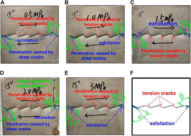
FIGURE 10. Failure form and crack penetration path of jointed rock mass with inclination angle of 15°. (A) Normal stress is 0.5 MPa. (B) Normal stress is 1 MPa. (C) Normal stress is 1.5 MPa. (D) Normal stress is 2 MPa. (E) Normal stress is 3 MPa. (F) Sketch of the rock damage state and the penetration path of the fracture.
The patterns of crack extension penetration and the forms of damage in the rock masses with joints inclined at 30°, 45°, and 60° as shown in Figures 11–13 were analyzed. It can be found that 1) with an increase in normal stress, multiple near-parallel cracks are produced in the rock bridges in the middle of both adjacent prefabricated joints; 2) with an increase in normal stress, the shear cracks in the rock sample gradually become obvious, the friction marks due to shear action gradually increase, and the area of the produced shear damage gradually increases. In particular, when the joints are inclined at 30° and 45° with an increase in normal stress, the cracks produced in the specimens gradually evolve from tension cracks to shear cracks (except when the joints are inclined at 45° and the normal stress is 3 MPa), and the damage forms of the specimens are changed from the initial tension damage to the composite damage of tension and shear; 3) the paths of crack expansion through the joints are different at three different angles of joint inclination. When the angle of joint inclination is 30°, most of the cracks produced connect the head and tail of the two adjacent joints, and a few cracks open from the tip of the precast joint and extend to the bridge above and below the tip. When the angle of joint inclination is 45°, most of these cracks start from the middle or tip of the precast joint and connect to the tip of the adjacent joint or extend directly to the bridge above and below the precast joint. When the angle of inclination of the joints is 60°, the new cracks produced do not connect the beginning and end of the two adjacent joints but mostly extend from the tip of the prefabricated joints directly to the upper and lower rock bridges of the specimen; and 4) the ranges of angles α and β differed at the three joint inclination angles of 30°, 45°, and 60°. Here, combined with the data of angle α and angle β when the angle of joint inclination is 15°, it is known that the angle α is in the range of 62–65°, 55–61°, 57–67°, and 51–62° and β is in the range of 58–66°, 57–63°, 52–60°, and 48–54° in the case of four different angles of the joint tilt, as shown in Table 4. It can be found that the pinch angle α and pinch angle β have a tendency to decrease with an increase in the tilt angle of the joints.
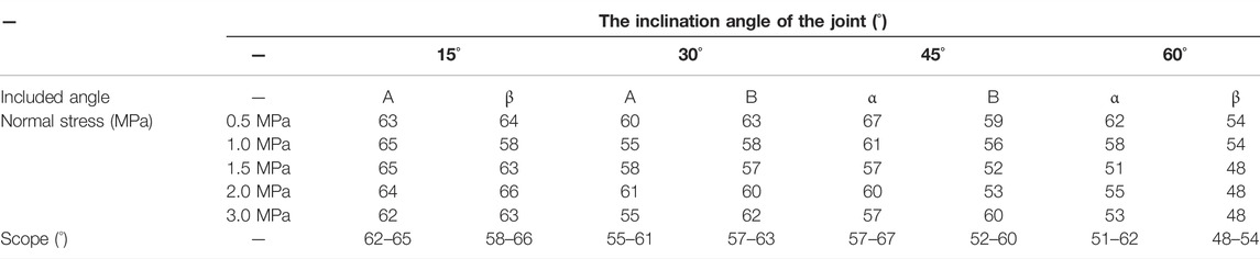
TABLE 4. Angles α and β under various working conditions.
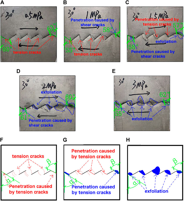
FIGURE 11. Failure form and crack penetration path of jointed rock mass with an inclination angle of 30°. (A) Normal stress is 0.5 MPa. (B) Normal stress is 1 MPa. (C) Normal stress is 1.5 MPa. (D) Normal stress is 2 MPa. (E) Normal stress is 3 MPa. (F–H) Sketch of the rock damage state and the penetration path of the fracture.
The aforementioned analysis mainly focuses on the crack expansion pattern and damage mode of the rock mass with an increase in normal stress at a certain tilt angle of the joints. In addition, we found that when the normal stress is fixed, with the change in the tilt angle of the joint the damage of the rock mass and the mode of crack extension penetration are changed. For example, by comparing Figure 9B, Figure 10B, Figure 11B, Figure 12B, and Figure 13B (i.e., Figures 9B–13B), we found that when the normal stress is 1 MPa and the section inclination angle is 0°, during the experiment some microelements inside the specimen may reach the tensile strength but fail to form macroscopic penetrating cracks due to the small number, but most of the microelements reach the shear strength and produce macroscopic penetrating shear cracks, which leads to the final shear damage of the specimen. The fixed normal stress is 1 MPa, and in the process of increasing the joint inclination angle from 0° to 60°, the tensile cracks in the rock mass keep increasing, macroscopic tensile crack groups gradually appear in the specimen, and macroscopic tensile cracks and shear cracks appear on the specimen surface at the same time so that the rock mass finally shows the tensile–shear composite damage mode. By comparing Figures 9A–13A, Figures 9C–13C, Figures 9D–13D, and Figures 9E–13E, it was found that the cracks produced at different inclination angles of the joints at normal stresses of 0.5 or 3.0 MPa also roughly followed this pattern. In summary, under the same normal stress condition, the tensile cracks produced in the rock mass gradually increase with an increase in the inclination angle of the joints, and the damage form of the rock mass changes from the initial shear damage to tensile–shear composite damage.

FIGURE 12. Failure form and crack penetration path of jointed rock mass with an inclination angle of 45°. (A) Normal stress is 0.5 MPa. (B) Normal stress is 1 MPa. (C) Normal stress is 1.5 MPa. (D) Normal stress is 2 MPa. (E) Normal stress is 3 MPa. (F–H) Sketch of the rock damage state and the penetration path of the fracture.
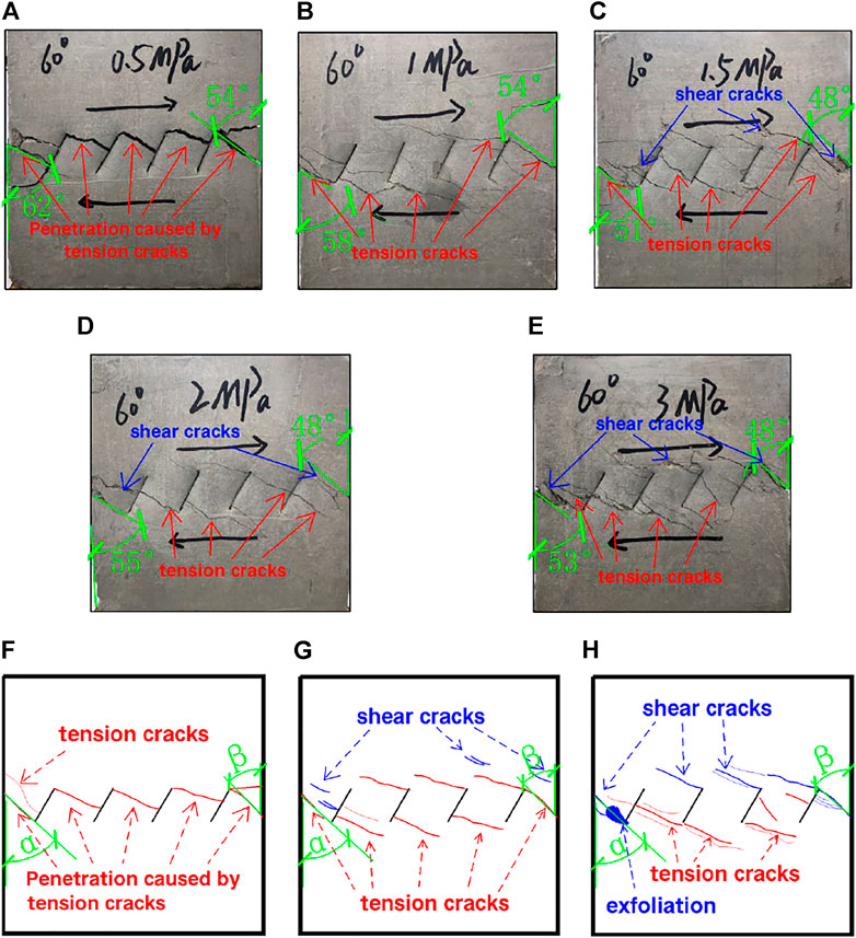
FIGURE 13. Failure form and crack penetration path of jointed rock mass with an inclination angle of 60°. (A) Normal stress is 0.5 MPa. (B) Normal stress is 1 MPa. (C) Normal stress is 1.5 MPa. (D) Normal stress is 2 MPa. (E) Normal stress is 3 MPa. (F–H) Sketch of the rock damage state and the penetration path of the fracture.
The aforementioned content analyzes the effects of the normal stress and tilt angle of joints on the macroscopic cracking and damage mode of rock masses, while the following content focuses on their effects on the strength characteristics of rock masses. Because the peak strength and the magnitude of residual strength of the rock mass can better reflect the strength characteristics of the rock mass, in order to study the effects of the normal stress and the tilt angle of the joints on the strength characteristics of the rock mass, we compiled the shear displacement–shear stress curves of all the rock mass specimens and divided them into two groups for analysis, as shown in Figures 14, 15. Among them, Figure 14 analyzes the displacement–stress curves of individual rock specimens under the conditions of single nodal tilt angle and different normal stresses. Figure 15 analyzes the displacement–stress curves of each rock specimen under the conditions of single normal stress and different nodal inclination angles.
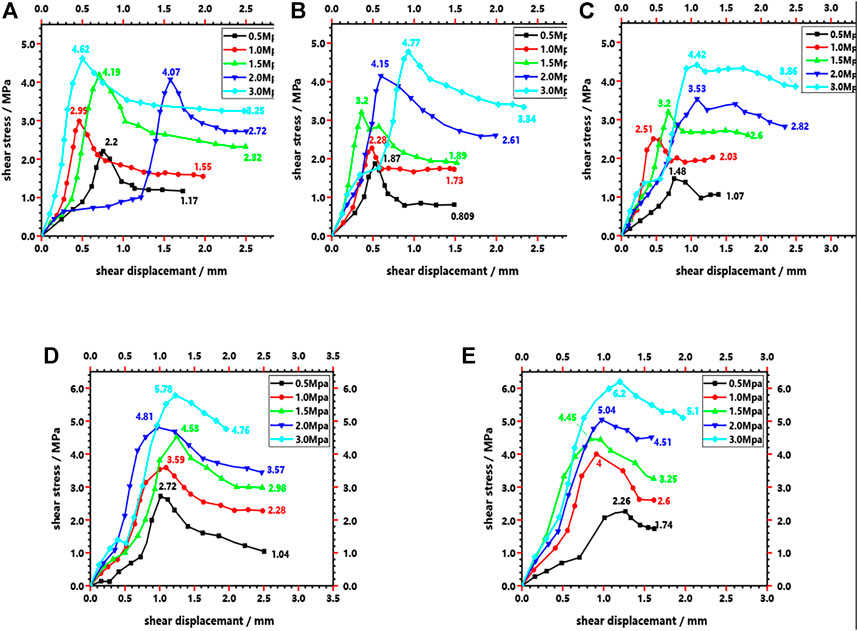
FIGURE 14. Curve of shear displacement–shear stress of the specimens under the condition of fifth-order normal stress. (A) Inclination angle is 0°. (B) Inclination angle is 15°. (C) Inclination angle is 30°. (D) Inclination angle is 45°. (E) Inclination angle is 60°.
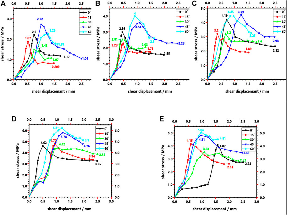
FIGURE 15. Curve of shear displacement–shear stress of the specimens with joints of different inclination angles. (A) Normal stress is 0.5 MPa (B) Normal stress is 1 MPa. (C) Normal stress is 1.5 MPa. (D) Normal stress is 2 MPa. (E) Normal stress is 3 MPa.
The significant effects of the normal stress and the tilt angle of the joints on the strength characteristics of the rock mass are shown in Figures 14, 15. On the one hand, as shown in Figure 14A, when the tilt angle of the joints is 0°, the peak shear stress of the rock mass increases from 2.2 to 4.62 MPa because the normal stress increases from 0.5 to 3.0 MPa, and the residual strength of the rock mass also increases from 1.17 to 3.25 MPa. Similarly, Figures 14A–E show that when the tilt angle of the joints is 15°, 30°, 45°, or 60°, the same pattern is observed. Therefore, the analysis of Figure 14 shows that the shear capacity of the rock mass is enhanced by an increase in the applied normal stress during the straight shear test. On the other hand, as shown in Figure 15A, at a normal stress of 0.5 MPa, the peak shear stress of the rock mass decreased from 2.2 to 1.48 MPa and then increased to 2.72 as the angle of inclination of the joints increased from 0° to 60° while the residual strength of the rock mass decreased from 1.17 to 0.81 MPa and then increased to 1.74. Similarly, Figures 15A–E show the same pattern when the normal stress is 1.0, 1.5, 2.0, or 3.0 MPa. Therefore, by analyzing the data in Figure 15 it can be shown that the increase in the inclination angle of the joints tends to decrease and then increase the shear capacity of the rock mass.
After the aforementioned research and discussion, this study concludes the following:
(1) When the inclination angle of the joint was 0° and 15°, the changing of the normal stress had little effect on the propagation and penetration path of the crack and the failure mode of the rock mass and only caused the area of the spalling blocks to be different. Moreover, when the joint inclination angle was 0°, shear failure occurred in the rock mass under various normal stress conditions, and when the joint inclination angle was 15°, the combined tensile–shear failure occurred in the rock mass.
(2) When the inclination angles of the joints were 30°, 45°, and 60°, with the increase in the normal stress, a number of nearly parallel cracks appeared in the rock bridge part between the two adjacent prefabricated joints in the rock specimens. With an increase in the normal stress, the shear cracks gradually become more obvious, the friction marks caused by the shearing action gradually increased, and the area of the damage gradually increased. Under these three inclination angles, with a change in normal stress, the failure mode of rock mass changed from tensile failure to tensile–shear composite failure.
(3) Under different inclination angles of joints, the propagation and penetration paths of cracks generated inside the rock mass and the damage mode of the rock mass were different. With an increase in joint inclination, the damage mode of the rock mass gradually changes from shear damage to tensile–shear composite damage. Additionally, changing the inclination angles of the joints resulted in different ranges for angles α and β. As the inclination angle of the joint increased, the angles α and β tended to decrease.
(4) The shear resistance of the rock mass was affected by the inclination angle of the joints and the normal pressure. The shear resistance of the rock mass was improved when the normal stress increased. Because the peak shear strength and residual strength of rock mass increased with an increase in the normal stress applied during shearing, within a limited range the shear resistance of rock mass had a tendency to decrease first and then increase. With an increase in the inclination angle of the joint, the peak shear strength and residual strength of the rock mass generally tended to decrease first and then to increase.
The datasets presented in this study can be found in online repositories. The names of the repository/repositories and accession number(s) can be found in the article/supplementary material.
All listed authors have made substantial, direct, and intellectual contributions to this work and have approved it for publication.
This work was supported by the Science and Technology Planning Project of Guizhou Province (Qiankehe Basic Project ZK (2022) General Project 082, Qiankehe Basic Project (2019) No.1057, and Qiankehe major special project (2018) 3011), the Regional First-Class Discipline Construction Project in Guizhou Province (QYNYL (2017) 0013), the Guiyang Metro Line 3 Phase I Engineering Research Project (Project No. GD3 -FW-YJ-05-2020-13-ZB), and the Scientific Research Project of Guiyang Rail Transit Line 2 Phase I Project (Project No. D2(I)-FW -YJ-2019-001-WT).
Author WW was employed by the company General Construction Co. of CCTEB Group Co., Ltd.
The authors declare that the research was conducted in the absence of any commercial or financial relationships that could be construed as a potential conflict of interest.
All claims expressed in this article are solely those of the authors and do not necessarily represent those of their affiliated organizations, or those of the publisher, the editors, and the reviewers. Any product that may be evaluated in this article, or claim that may be made by its manufacturer, is not guaranteed or endorsed by the publisher.
Bai, S., Ren, W., Feng, D., and Zhou, S. (1999). Direct Shear Strength Characteristics of Coplanar Closed Discontinuous Jointed Rock Mass. Rock Soil Mech. 20. (in Chinese). doi:10.16285/j.rsm.1999.02.003
Ban, L., Du, W., Jin, T., Qi, C., and Li, X. (2021). A Roughness Parameter Considering Joint Material Properties and Peak Shear Strength Model for Rock Joints. Int. J. Min. Sci. Technol. 31 (3), 413–420. doi:10.1016/j.ijmst.2021.03.007
Cao, R. H., Cao, P., Lin, H., Ma, G. W., Fan, X., and Xiong, X. G. (2018). Mechanical Behavior of an Opening in a Jointed Rock-like Specimen under Uniaxial Loading: Experimental Studies and Particle Mechanics Approach. Archives Civ. Mech. Eng. 18 (1), 198–214. doi:10.1016/j.acme.2017.06.010
Cao, R., Yao, R., Hu, T., Wang, C., Li, K., and Meng, J. (2020). Failure and Mechanical Behavior of Transversely Isotropic Rock under Compression-Shear Tests: Laboratory Testing and Numerical Simulation. Eng. Fract. Mech. 241, 107389. (in Chinese). doi:10.1016/j.engfracmech.2020.107389
Chen, M. (2019). Research on Damage Mechanical Characteristics and Anchorage Control Mechanism of Discontinuous Jointed Rock Mass. Wuhan, Hubei, China: China University of Mining and Technology. (in Chinese). doi:10.27623/d.cnki.gzkyu.2019.000145
Chen, Q., Zhang, Y., Liu, Y., Wang, W., and Cao, K. (2020). Influence of Joint Undulation Angle on Mechanical Properties of Non-penetrated Joint Rock Mass. J. Undergr. Space Eng. 16 (02), 351–358+365. (in Chinese).
Dong, L., Chen, Y., Sun, D., and Zhang, Y. (2021). Implications for Rock Instability Precursors and Principal Stress Direction from Rock Acoustic Experiments. Int. J. Min. Sci. Technol. 31, 789–798. doi:10.1016/j.ijmst.2021.06.006
Fan, X., Jiang, X., Liu, Y., Lin, H., Li, K., and He, Z. (2021b). Local Stress Distribution and Evolution Surrounding Flaw and Opening within Rock Block under Uniaxial Compression. Theor. Appl. Fract. Mech. 112, 102914. doi:10.1016/j.tafmec.2021.102914
Fan, X., Yang, Z., and Li, K. (2021a). Effects of the Lining Structure on Mechanical and Fracturing Behaviors of Four-Arc Shaped Tunnels in a Jointed Rock Mass under Uniaxial Compression. Theor. Appl. Fract. Mech. 112, 102887. doi:10.1016/j.tafmec.2020.102887
Gao, Q., Cao, P., Wang, F., and Wang, Z. (2019). Mechanical Properties and Failure Criteria of Multi-Joint Rock-like Specimens under Compression-Shear. Rock Soil Mech. 40 (03), 1013–1022. (in Chinese). doi:10.16285/j.rsm.2017.2021
Guo, L., Wu, Y., Ren, K., Zheng, L., and Zhang, H. (2022). Study on Dynamic Response of Rock Slope with Inverse Non-persistent Joints under Earthquake. Front. Earth Sci. 10, 838387. doi:10.3389/feart.2022.838387
He, P., Li, S., Li, L., Xu, Z., and Shi, S. (2018). Discontinuous Deformation Analysis of Surrounding Rock for Small Space Tunnel with Super Large Section in Jointed Rock Mass. J. Geotechnical Eng. 40 (10), 1889–1896. doi:10.11779/CJGE201810016
Hu, G., Ma, G., Liang, W., Song, L., and Fu, W. (2022). Influence of the Number of Parallel-Joints on Size Effect of Elastic Modulus and Characteristic Elastic Modulus. Front. Earth Sci. 10, 862850. doi:10.3389/feart.2022.862850
Huang, Y.-H., and Yang, S.-Q. (2018). Mechanical and Cracking Behavior of Granite Containing Two Coplanar Flaws under Conventional Triaxial Compression. Int. J. Damage Mech. 28, 590–610. doi:10.1177/1056789518780214
Li, Y., Qi, T., Lei, B., Qian, W., and Li, Z. (2019). Deformation Patterns and Surface Settlement Trough in Stratified Jointed Rock in Tunnel Excavation. KSCE J. Civ. Eng. 23 (7), 3188–3199. doi:10.1007/s12205-019-0477-4
Lin, Q., Cao, P., Liu, Y., Cao, R., and Li, J. (2021a). Mechanical Behaviour of a Jointed Rock Mass with a Circular Hole under Compression-Shear Loading: Experimental and Numerical Studies. Theor. Appl. Fract. Mech. 114, 102998. doi:10.1016/j.tafmec.2021.102998
Lin, Q., Cao, P., Wen, G., Meng, J., Cao, R., and Zhao, Z. (2021b). Crack Coalescence in Rock-like Specimens with Two Dissimilar Layers and Pre-existing Double Parallel Joints under Uniaxial Compression. Int. J. Rock Mech. Min. Sci. 139, 104621. doi:10.1016/j.ijrmms.2021.104621
Liu, G., Jiang, Q., Xiong, F., and Zhang, X. (2016). Experiment Study of Crack Propagation and Deformation Failure of Multiple-Jointed Rock Mass. Rock Soil Mech. 37 (S1), 151–158. (in Chinese). doi:10.16285/j.rsm.2016.S1.020
Liu, Y., Zhang, S., Liu, J., and Xia, C. (2013). Research on Rock Mass Containing Discontinuous Joints with Different Joint Surface Topography by Model Test. J. Undergr. Space Eng. 9, 744–748+764. (in Chinese).
Ma, H., Song, Y., Chen, S., Yin, D., Zheng, J., Shen, F., et al. (2021). Experimental Investigation on the Mechanical Behavior and Damage Evolution Mechanism of Water-Immersed Gypsum Rock. Rock Mech. Rock Eng. 54 (9), 4929–4948. doi:10.1007/s00603-021-02548-2
Mei, J., Yang, L., Sheng, X., Song, G., Yang, W., and Zhang, B. (2019). Time-Dependent Propagation of 3-D Cracks in Rocks under Hydromechanical Coupling. Rock Mech. Rock Eng 53, 1923–1934. doi:10.1007/s00603-019-02020-2
Niu, Y., Zhou, X. P., and Zhou, L. S. (2019). Fracture Damage Prediction in Fissured Red Sandstone under Uniaxial Compression: Acoustic Emission B ‐value Analysis. Fatigue Fract. Eng. Mater Struct. 43, 175–190. doi:10.1111/ffe.13113
Pu, Z., Cao, P., Zhao, Y., Zhang, X., and Yi, Y. (2010). Numerical Analysis and Strength Experiment of Rock-like Materials with Multi-Fissures under Uniaxial Compression. Rock Soil Mech. 31 (11), 3661–3666. (in Chinese). doi:10.16285/j.rsm.2010.11.038
Schwartzkopff, A. K., Melkoumian, N. S., and Xu, C. (2020). Breakdown Pressure and Propagation Surface of a Hydraulically Pressurized Circular Notch within a Rock Material. Rock Mech. Rock Eng. 54, 191–218. doi:10.1007/s00603-020-02264-3
Shaunik, D., and Singh, M. (2020). Bearing Capacity of Foundations on Rock Slopes Intersected by Non-persistent Discontinuity. Int. J. Min. Sci. Technol. 30, 669–674. doi:10.1016/j.ijmst.2020.03.018
Song, R., Wang, Y., Ishutov, S., Zambrano-Narvaez, G., Hodder, K. J., Chalaturnyk, R. J., et al. (2020). A Comprehensive Experimental Study on Mechanical Behavior, Microstructure and Transport Properties of 3D-Printed Rock Analogs. Rock Mech. Rock Eng. 53, 5745–5765. doi:10.1007/s00603-020-02239-4
Tian, J., Xu, D., and Liu, T. (2020). An Experimental Investigation of the Fracturing Behaviour of Rock-like Materials Containing Two V-Shaped Parallelogram Flaws. Int. J. Min. Sci. Technol. 30, 777–783. doi:10.1016/j.ijmst.2020.07.002
Wang, G., Zhang, L., Xu, M., Liang, Z., and Ran, L. (2019). Energy Damage Evolution Mechanism of Non-across Jointed Rock Mass under Uniaxial Compression. J. Geotechnical Eng. 41 (04), 639–647. (in Chinese). doi:10.11779/CJGE201904006
Wang, W. (2020). Research on Extended Penetration of Non-coplanar Non-penetrating Jointed Rrock Mass. Guiyang, Guizhou, China: Guizhou University. (in Chinese).
Xia, K., Chen, C., Wang, T., Zheng, Y., and Wang, Y. (2022). Estimating the Geological Strength Index and Disturbance Factor in the Hoek-Brown Criterion Using the Acoustic Wave Velocity in the Rock Mass. Eng. Geol. 306, 106745. doi:10.1016/j.enggeo.2022.106745
Xia, K., Chen, C., Yang, K., Sun, C., Liu, X., and Zhou, Y. (2020). Influence of Relative Humidity on the Non-linear Failure and Stability of Gypsum Mines. Eur. J. Environ. Civ. Eng. 26, 1518–1543. doi:10.1080/19648189.2020.1715850
Xia, K., Chen, C., Zhou, Y., Liu, X., Zheng, Y., and Pan, Y. (2019). Catastrophe Instability Mechanism of the Pillar-Roof System in Gypsum Mines Due to the Influence of Relative Humidity. Int. J. Geomechanics 19 (4), 06019004. doi:10.1061/(asce)gm.1943-5622.0001378
Xu, Q., Jiang, L., Ma, C., Niu, Q., and Wang, X. (2021). Effect of Layer Thickness on the Physical and Mechanical Properties of Sand Powder 3D Printing Specimens. Front. Earth Sci. 9, 763202. doi:10.3389/feart.2021.763202
Yang, S.-Q., Yin, P.-F., Zhang, Y.-C., Chen, M., Zhou, X.-P., Jing, H.-W., et al. (2019). Failure Behavior and Crack Evolution Mechanism of a Non-persistent Jointed Rock Mass Containing a Circular Hole. Int. J. Rock Mech. Min. Sci. 114, 101–121. doi:10.1016/j.ijrmms.2018.12.017
Yang, Y., Xu, D., Liu, F., and Zheng, H. (2020). Modeling the Entire Progressive Failure Process of Rock Slopes Using a Strength-Based Criterion. Comput. Geotechnics 126, 103726. doi:10.1016/j.compgeo.2020.103726
Yang Y., Y., Sun, G., Zheng, H., and Qi, Y. (2019). Investigation of the Sequential Excavation of a Soil-Rock-Mixture Slope Using the Numerical Manifold Method. Eng. Geol. 256, 93–109. doi:10.1016/j.enggeo.2019.05.005
Zhang, B., Li, S., Yang, X., Zhang, D., and Shao, C. (2012). Uniaxial Compression Tests on Mechanical Properties of Rock Mass Similar Material with Cross-Cracks. Rock Soil Mech. 33 (12), 3674–3679. (in Chinese). doi:10.16285/j.rsm.2012.12.017
Zheng, H., Yang, Y., and Shi, G. (2019). Reformulation of Dynamic Crack Propagation Using the Numerical Manifold Method. Eng. Analysis Bound. Elem. 105, 279–295. doi:10.1016/j.enganabound.201910.1016/j.enganabound.2019.04.023
Zheng, Z., Su, G., Jiang, Q., Pan, P., Huang, X., and Jiang, J. (2022). Mechanical Behavior and Failure Mechanisms of Cylindrical and Prismatic Rock Specimens under Various Confining Stresses. Int. J. Damage Mech. 31 (6), 864–881. doi:10.1177/10567895221083997
Zhou, X.-P., Wang, Y.-T., Zhang, J.-Z., and Liu, F.-N. (2018). Fracturing Behavior Study of Three-Flawed Specimens by Uniaxial Compression and 3D Digital Image Correlation: Sensitivity to Brittleness. Rock Mech. Rock Eng. 52, 691–718. doi:10.1007/s00603-018-1600-4
Keywords: rock-like material, different inclination angles, groups of parallel joints, crack propagation path, failure mode, strength properties
Citation: Chen Q, Liu Y, Wang W, Ou X, Zhou Y, Teng Z and Tian X (2022) Effects of Normal Stress and Joint Inclination Angle on Rock Failure Characteristics Under Compression–Shear Conditions. Front. Earth Sci. 10:950648. doi: 10.3389/feart.2022.950648
Received: 23 May 2022; Accepted: 08 June 2022;
Published: 18 July 2022.
Edited by:
Yongtao Yang, Institute of Rock and Soil Mechanics (CAS), ChinaReviewed by:
Rui Kong, Northeastern University, ChinaCopyright © 2022 Chen, Liu, Wang, Ou, Zhou, Teng and Tian. This is an open-access article distributed under the terms of the Creative Commons Attribution License (CC BY). The use, distribution or reproduction in other forums is permitted, provided the original author(s) and the copyright owner(s) are credited and that the original publication in this journal is cited, in accordance with accepted academic practice. No use, distribution or reproduction is permitted which does not comply with these terms.
*Correspondence: Yuanming Liu, bGl1eW1fMjAyMUAxNjMuY29t
Disclaimer: All claims expressed in this article are solely those of the authors and do not necessarily represent those of their affiliated organizations, or those of the publisher, the editors and the reviewers. Any product that may be evaluated in this article or claim that may be made by its manufacturer is not guaranteed or endorsed by the publisher.
Research integrity at Frontiers
Learn more about the work of our research integrity team to safeguard the quality of each article we publish.