 Juejing Fang
 Ke Yang
 Xin Lyu1,2
 Jiqiang Zhang
- 1State Key Laboratory of Mining Response and Disaster Prevention and Control in Deep Coal Mines, Anhui University of Science and Technology, Huainan, China
- 2Coal Mine Safety Mining Equipment Innovation Center of Anhui Province, Anhui University of Science and Technology, Huainan, China
- 3Institute of Energy, Hefei Comprehensive National Science Center, Hefei, China
- 4Guizhou Provincial Key Laboratory of Rock and Soil Mechanics and Engineering Safety, Guizhou University, Guiyang, China
Uniaxial compression tests were carried on 12 concrete specimens with six different diameter holes using a rigid test machine, and the stress–strain relationship was analyzed in different hole diameter specimens. The effects of different hole diameters on specimen compression strength, elastic modulus, and Poisson’s ratio were studied, and the failure form and instability mode of concrete specimens with holes of different diameters were evaluated. The results show that the larger the compression strength of the specimen, the larger the axial and horizontal strains. As the hole diameter increased from 0 to 50 mm, the compression strength and elastic modulus reduced. The decreasing trend slowed down, and the relationships between the hole diameter and compression strength, and elastic modulus could be represented by negative liner functions. The Poisson ratio of the specimen increased in waves with the increase in hole diameter from 0 to 50 mm. A crack in the concrete specimen with 0–20 mm diameter hole started at the upper and lower diagonal angles of the hole wall; a crack in the concrete specimen with 30–50 mm diameter hole started at the left and right parts of the hole wall. The instability mode of concrete specimens with horizontal holes of different diameters was divided into shear dislocation instability and planar splitting instability.
Introduction
The surrounding rock is transformed from brittle to plastic with increasing mining depth due to high stress (Li et al., 2019; Xie et al., 2021). The main methods used to control the gateway surrounding rock include a combination of releasing surrounding rock stress and using a low-cost support instead of improving the support strength involving increasing costs (He et al., 2021; Kang 2021; Wu et al., 2021; Wang et al., 2022b). Pressure-relief drill parameters affect the release of surrounding rock stress and the continuous deformation; selecting proper pressure-relief drill diameters is an important step to control deep gateway surrounding rocks (Gao et al., 2020; Zhang et al., 2022).
Recently, studies on the drilling pressure-relief of high-stress weak gateway surrounding rocks have improved (Pu et al., 2020; Zuo et al., 2021). Based on the analysis of the mechanism of drill pressure-relief in deep gateway surrounding rocks, a method determining drill parameters was developed, and the precrack failure of gateway sides’ surrounding rock could be realized by the rational distribution of pressure-relief drills. The unloading effect within a surrounding rock was studied under cyclic excavation; the mechanism of pressure relief and structural stability of hard roof along the roadway was elucidated; and elastic stress analysis and plastic zone estimation in pressure-relief gateway were carried out using the complex variable method (Xu et al., 2019; Zhao et al., 2020; Kan et al., 2022). Based on the impact of energy dissipation by pre-excavation pressure release, technologies combining the reinforcing of surrounding rock and pressure relief, anchoring grouting, and floor pressure relief were proposed to prevent the rock burst in deep gateway (Zhai et al., 2018; Wang et al., 2022a). The failure characteristics of rocks with different holes and fractures have been studied in the laboratory (Gou et al., 2007; You et al., 2020). The strength and fracturing of rocks with inclining cracks and holes in different locations and shapes were also studied (Wu et al., 2017; Wang et al., 2020). The failure processes of intact, single-hole, double-hole, single-hole double-crack, double-hole single-crack, and defect specimens were analyzed (Zhao et al., 2017; Fan et al., 2018; Chen et al., 2020; Wu et al., 2020), and the mechanism of crack coalescence in surrounding rocks with different holes was elucidated. With the improvement of monitoring and experimental level, the relationship between creep failure stress and horizontal hole was studied (Xin et al., 2018; Wang et al., 2019); acoustic emission monitoring and digital imaging systems were used to conduct uniaxial compression tests of sandstone specimens with cracks and elliptical holes (Liu et al., 2019; Du et al., 2020; Fan et al., 2022); and the surface potential change characteristics of the concrete wall with holes under uniaxial compression were tested (Liu et al., 2014). With studies on the characteristics of concrete and application of concrete technology in coal mines (Gao et al., 2015; Lyu et al., 2021), attention has been paid to the characteristics of concrete holes, which undoubtedly provides a good research basis for this test.
In the study, uniaxial compression tests were carried out on 12 concrete specimens with six different diameter holes using a rigid test machine, and the stress–strain relationship of different hole diameter specimens was analyzed. The effects of different hole diameters on specimen compression strength, elastic modulus, and Poisson’s ratio, were studied, and the failure form and instability mode of concrete specimens with holes of different diameters were evaluated. The results provide references for selecting the hole diameter and sealing-hole design of deep gateway surrounding rocks.
Test design
Specimen preparation
The concrete specimens were prepared from C32.5 cement and water with a ratio of 1:0.3 in a square standard mold of 100 mm × 100 mm × 100 mm (Figure 1A). The holes in the specimens were reserved using PVC tubes (Figure 1B) with diameters of 10, 20, 30, 40, and 50 mm, which were immobilized in the center of the square mold (Figure 2). Before preparing concrete specimens, the inside of the molds and the surface of the tubes were greased to release the specimens easily.
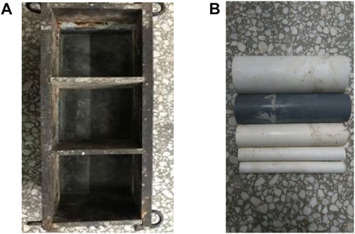
FIGURE 1. Molds for concrete specimens. (A) Filling mold. (B) Perforated tubes.
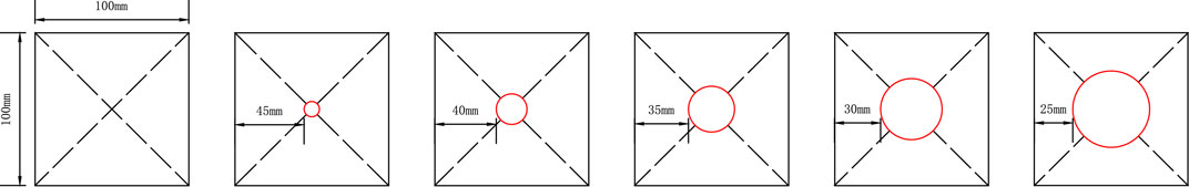
FIGURE 2. Hole design in concrete specimens.
Eighteen specimens were tested. According to the hole diameter, these specimens were divided into six groups, namely, group A, group B, group C, group D, group E, and group F; each group had three specimens. The prefabricated concrete specimens were demolded after 24 h, and water was sprayed for 28 days (Figure 3). The loading roughness end of the specimens was grinded well to a nonparallelism of less than 0.02 mm. The prefabrication influenced the hole height and inclination; for accuracy, two specimens with less dissimilarity were selected from each group for the uniaxial compression test.
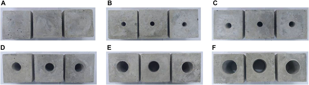
FIGURE 3. Prefabricated concrete specimens. (A) 0 mm, (B) 10 mm, (C) 20 mm, (D) 30 mm, (E) 40 mm, and (F) 50 mm.
Test mothed
The displace loading test was conducted using a full-servo test system controlled using a computer, and the loading rate was 0.03 mm/s. The axial and lateral deformations of the specimens were acquired using digital micrometers. The load was controlled and collected using a software, and all the test data were recorded and saved automatically using a computer. The whole stress–strain curve of uniaxial compression concrete specimens with holes of different diameters could be obtained.
Test result analysis
The specimen B2 was not analyzed because of more data difference, which was reloaded after being damaged. The other specimens were subjected to the whole uniaxial compression (Figure 4); the uniaxial compression data are shown in Table 1.
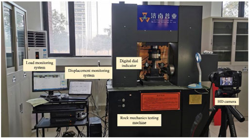
FIGURE 4. Test process.
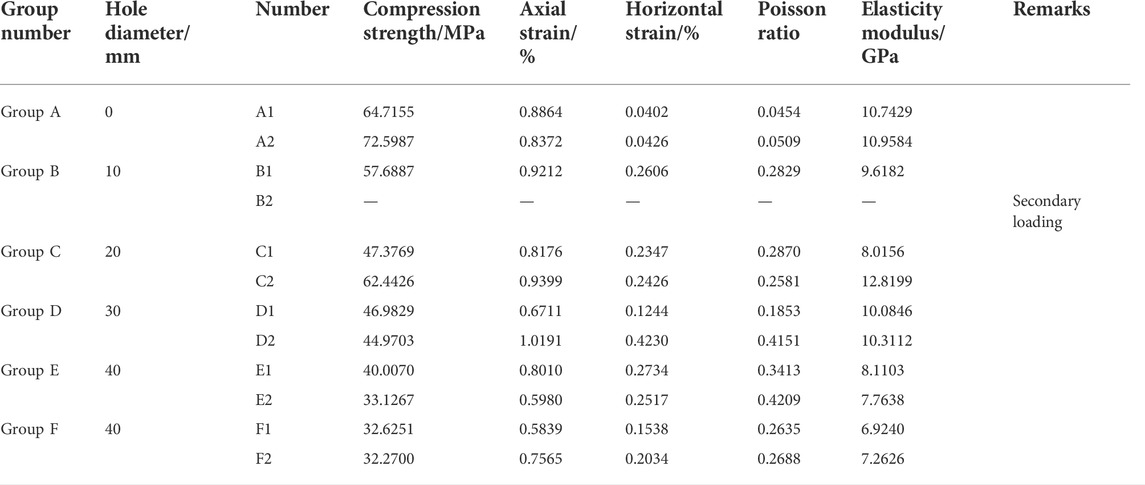
TABLE 1. Uniaxial compression data.
Analysis of test results
Characteristics of stress–strain curves
Figure 5 shows that the whole stress–strain curve of uniaxial compression concrete specimen with holes of different diameters has five stages: origin void compaction, linear elasticity, elastic–plastic transition, plastic, and failure. The linear elasticity stage was longer, and the elastic–plastic transition and plastic stage were not obvious. It was found that concrete specimens had good elastic deformation.
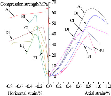
FIGURE 5. Stress–strain curves of uniaxial compression on specimens.
The higher the compression strength, the larger the axial strain and horizontal strain on the concrete specimen with holes of different diameters. The axial strain was more than the horizontal strain in the same-hole specimen, while the axial strain growth was less than the horizontal strain growth. The average axial strain decreased with increasing hole diameter. When the hole diameter increased from 0 to 30 mm, the axial strain was less, and the horizontal strain first increased and then decreased. When the hole diameter was 30 mm, the horizontal strain reached the maximum and then decreased.
Relationship between horizontal-hole diameter and compression strength
Figure 6 shows the relationship between the hole diameter and compression strength of concrete specimens. When the hole diameter increased from 0 to 50 mm, the average compression strength of the concrete specimen with different hole diameters decreased from 68.6571 to 57.6887, 54.9098, 45.9766, 36.5669, and 32.4476 MPa, and the average compression damping range was 52.74%. This shows that the larger the hole diameter, the lower the strength of concrete specimen.
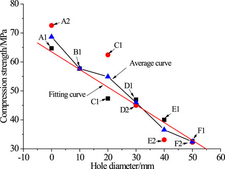
FIGURE 6. Relationship between the hole diameter and compression strength.
Figure 7 shows the relationship between the hole diameter and compression damping of concrete specimens. The hole diameter increased from 0 to 50 mm, and the compression damping range of hole specimens increased more linearly than that of intact specimens. The average decrease rate of the compression strength of concrete specimens with holes of different diameters to the specimen with previous hole diameter was, in turn, 15.9756%, 4.8171%, 16.2689%, 20.4663%, and 11.2651%, i.e., the average increasing rate of compression strength compared to the previous hole diameter specimen is 13.7586%. When the hole diameter was 20 mm, the decrease in compression strength was the least, which could explain why the hole slightly affected the compression strength of concrete specimens when the hole diameter was less than 20 mm. When the hole diameter increased from 20 to 30 mm, a large decrease in the compression strength of concrete specimens was observed, and the failure form was obviously different.
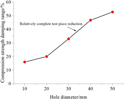
FIGURE 7. Relationship between the hole diameter and compression strength damping range.
The fitting relationship between the hole diameter and compression strength of concrete specimens can be expressed as follows:
where
The correlation coefficient was
Relationship between horizontal-hole diameter and elasticity modulus
The elasticity modulus of the concrete specimen with holes of different diameters was obtained by fitting and calculating the approximate linear data of the whole stress–strain curve, which occurred before specimen failure.
Figure 8 shows the relationship between the hole diameter and elasticity modulus of concrete specimens. The elasticity modulus of the concrete specimen with the same hole diameter was similar except that with a 20 mm diameter hole, which was larger than that with a 10 mm diameter hole. The elasticity modulus of the concrete specimen with a 0–30 mm diameter hole was little difference, indicating that the 0–30 mm diameter hole slightly affected the elastic modulus of concrete specimens. When the hole diameter was more than 30 mm, the elasticity modulus damping increased, and the most damping rate was 22.1693% of the previous hole diameter specimen. The elasticity modulus damping rate of concrete specimens decreased when the hole diameter was 50 mm. In the whole, the average elasticity modulus of concrete specimens with holes of different diameters decreased with the increase in hole diameter from 0 to 50 mm.
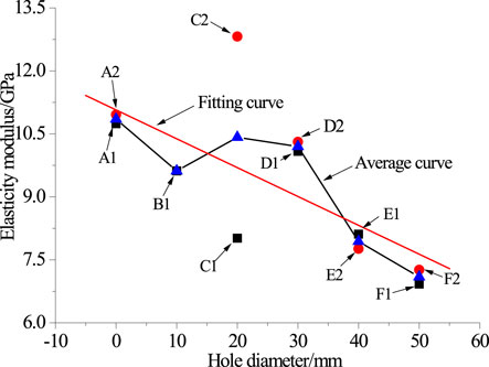
FIGURE 8. Relationship between the hole diameter and elasticity modulus.
Figure 9 shows the relationship between the hole diameter and elasticity modulus damping of concrete specimens. The elasticity modulus damping range of hole specimens to the intact specimen first decreased and then increased with the increase in hole diameter from 0 to 50 mm. The elasticity modulus of the concrete specimen slightly changed when the hole diameter was 0–30 mm, and the damping rate was 6.0162%, indicating that the hole diameter slightly affected the elasticity modulus of the concrete specimen. When hole diameter increased from 30 to 50 mm, the elasticity modulus damping range was 30.4435%, indicating that 30–50 mm hole diameter affected the elasticity modulus of concrete specimens.
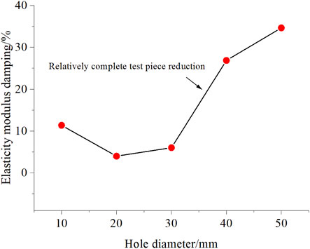
FIGURE 9. Relationship between the hole diameter and elasticity modulus damping.
On the whole, 20–30 mm hole diameter was the key range affecting the mechanics parameters. When the hole diameter increased from 0 to 50 mm, the elasticity modulus damping was 34.6282%, indicating that the larger the hole diameter of concrete specimen, the lower the elasticity modulus.
The fitting relationship between the hole diameter and elasticity modulus can be expressed as follows:
where
The correlation coefficient
Relationship between horizontal-hole diameter and Poisson’s ratio
Figure 10 shows the relationship between the hole diameter and Poisson ratio of concrete specimens. When the hole diameter increased from 0 to 50 mm, the Poisson ratio first increased and then decreased, and the whole increasing range was 452.2822%. The Poisson ratio of no-hole concrete specimens was the least, and that of 50 mm hole diameter specimens was the second. When the hole diameter increased from 10 to 50 mm except no-hole concrete specimens, the Poisson ratio slightly changed, so the hole diameter slightly affected the Poisson ratio of concrete specimens.
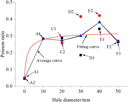
FIGURE 10. Relationship between the hole diameter and Poisson ratio.
Figure 11 shows the relationship between the hole diameter and Poisson ratio of concrete specimens. Poisson’s ratio of hole concrete specimens increased with the increase in hole diameter from 0 to 50 mm, and the increasing range of 40 mm diameter concrete specimens was larger. The increasing ranges of the other specimens (10 mm, 20 mm, 30 mm, and 50 mm) were 486.9295%, 465.5620%, 522.8216%, and 452.2822%, respectively. The largest change rate was 15.60%, indicating that the hole diameter slightly affected Poisson’s ratio of concrete specimens.
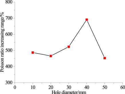
FIGURE 11. Relationship between the hole diameter and Poisson ratio increasing range.
The fitting relationship between the hole diameter and Poisson ratio of concrete specimens can be expressed using the following equation:
where
The correlation coefficient
Relationship between horizontal-hole diameter and failure mode
Failure mode of concrete specimen with holes of different diameters
Figure 12 shows the failure mode of concrete specimens with holes of different diameters. Figure 13 shows the failure mode. Figures 12, 13 show some common and different characteristics of failure mode. The common characteristics are that the main fracture surface occurred in all failure concrete specimens and controlled failure mode; all concrete specimens were damaged along the hole diameter, which controlled the specimen failure mode. The different characteristics are as follows: The main fracture surface angle of concrete specimens with holes of different diameters was different; the failure mode of concrete specimens with holes of different diameters failed differently along the hole diameter.
FIGURE 12. Failure forms of concrete specimens with holes of different diameters. (A) 0 mm, (B) 10 mm, (C) 20 mm, (D) 30 mm, (E) 40 mm, and (F) 50 mm.
FIGURE 13. Failure-mode sketch of concrete specimens with holes of different diameters. (A) 0 mm, (B) 10 mm, (C) 20 mm, (D) 30 mm, (E) 40 mm, and (F) 50 mm.
In summary, as the hole diameter increased from 0 to 50 mm, the concrete specimens failed from near-friction-angle compression shear to vertical compression splitting.
The concrete specimen with 0–30 mm diameter hole showed shear failure along the diagonal of hole diameter. The larger the hole diameter, the smaller the fracture block, the less surface fell off, the more obvious the main control surface, the second control surface initiated, the number of reverse crack increased, the hole displaced along the transverse direction, and the failure mode of concrete specimens became complex.
The concrete specimen with 40–50 mm diameter hole showed flake splitting failure from multiple cracks in the left and right sides of hole, indicating that the cracks easily initiated in the stress-concentrated points during uniaxial compression on large-hole concrete specimens. In the concrete specimens with holes of 40 and 50 mm diameters, the boundary of the main and second failure surface was vague, the number of reverse tensile cracks gradually decreased, and the hole collapsed. The larger the hole diameter of concrete specimens, the smaller the fracture blocks, the more severe the hole collapsed.
Figure 14 shows the failure mode of holes of the wall of different diameters. In the small hole (the hole diameter was less than 20–30 mm), the hole wall displaced to fail along one direction, the upper and the lower parts of the failure hole dislocated, and the rupture surface run through the whole hole. In the large hole (the hole diameter was more than 20–30 mm), the hole wall was compressed to fail along the loaded direction, the upper and lower parts of hole did not dislocate, mainly compression failure occurred, the upper compression wall was larger than the lower compression wall, and the compression offshoring instability was observed in the upper part of the hole.
FIGURE 14. Hole-wall failure modes of concrete specimens with holes of different diameters. (A) 20 mm and (B) 50 mm.
Instability mode of concrete specimens with holes of different diameters
According to the hole diameter, the instability modes of concrete specimens were divided into two types (Figure 15): small-diameter-hole shear displaced instability and large-diameter-hole flake splitting stability.
FIGURE 15. Failure modes of concrete specimens with holes of different diameters. (A) Small-diameter-hole shear displaced instability. (B) Large-hole-diameter flake splitting instability.
Small-diameter-hole shear displaced instability. When the hole diameter of concrete specimens was small, the concrete specimens were transformed into plastic stage, and cracks occurred with the increase in stress. In the concrete specimens with holes of 0 or 20 mm diameters, the cracks initiated at the upper and lower inclined angles of the hole wall, the upper and lower cracks extended to the upper and lower angles of concrete specimens with the increase in axial stress, and partial microcracks initiated to break through the upper and lower parts of hole wall angles to fail, i.e., small-diameter-hole shear displaced instability. Group C belonged to small-diameter-hole shear displaced instability.
Large-hole-diameter flake splitting instability: When the hole diameter of concrete specimens was large, the concrete specimens were transformed into the plastic stage, and cracks occurred with the increase in stress. In concrete specimens with holes of 30 or 50 mm diameter, the crack initiated in the left and right sides of the hole, and extended vertically to the upper and lower surfaces of concrete specimens, and then collapsed to fail vertically along the left and right wall of hole, indicating large-diameter-hole flake splitting instability. Group E belonged to the large-diameter-hole flake splitting instability.
Conclusion
In this study, the mechanical properties of concrete specimens with different pore sizes were studied from the aspects of stress–strain relationship, compressive strength, elastic modulus, Poisson’s ratio, failure mode, and instability mode. The following conclusions can be drawn based on the experimental analysis and discussion.
1) The whole uniaxial compression stress–strain curve of concrete specimens with horizontal holes of different diameters had five stages similar to intact specimens. The larger the compression strength of the hole of concrete specimens, the higher the axial and horizontal strains.
2) With the increase in hole diameter from 0 to 50 mm, the compression strength and elasticity modulus of concrete specimens decreased, and the trend slowed down. The damping rates were 52.7396% and 34.6282%, and the relationships between hole diameter and compression strength, and elasticity modulus could be expressed using a negative linear formula.
3) With the hole diameter increasing from 0 to 50 mm, Poisson’s ratio of concrete specimens increased wholly wave. Poisson’s ratio increased slowly with increasing hole diameter. Holes with different diameters had little effect on Poisson’s ratio of concrete specimens, but the existence of pore diameters had a great influence on the specimens.
4) In the concrete specimens with 0–30 mm diameter holes, the crack passed through the hole along the diagonal; the larger the diameter, the smaller the fracture block, the less the surface shedding, and the more obvious the main control surface, showing the shear displacement instability of the small-diameter-hole. In the concrete specimens with holes of 40–50 mm diameter, the crack occurred around the hole and flake splitting occurred in the hole; the larger the diameter, the smaller the fracture block, and the more severe hole failed, which is manifested as large-diameter-hole flaky splitting instability.
Data availability statement
The original contributions presented in the study are included in the article/Supplementary Material; further inquiries can be directed to the corresponding author.
Author contributions
Conceptualization, JF and KY; methodology, JF and XL; software, JF, KY, and XL; validation, JT and JZ; writing—original draft preparation, JF; writing—review and editing, KY, XL, and JT; and project administration, JZ. All authors have read and agreed to the published version of the manuscript.
Funding
This work was supported by the Institute of Energy, the Hefei Comprehensive National Science Center Project (21KZS215), the National Program on Key Basic Research Project of China (2019YFC1904304), the Graduate Innovation Fund project of Anhui University of Science and Technology (2021CX 2016), the Key Research and Development Plan of Anhui Province (202104a07020009), the Anhui Provincial Department of Science and Technology University Research Project (YJS20210391), and the Guizhou Provincial Science and Technology Projects ([2020]2004).
Conflict of interest
The authors declare that the research was conducted in the absence of any commercial or financial relationships that could be construed as a potential conflict of interest.
Publisher’s Note
All claims expressed in this article are solely those of the authors and do not necessarily represent those of their affiliated organizations, or those of the publisher, the editors, and the reviewers. Any product that may be evaluated in this article, or claim that may be made by its manufacturer, is not guaranteed or endorsed by the publisher.
References
Chen, S., Xia, Z., and Feng, F. (2020). Numerical simulation of strength, deformation, and failure characteristics of rock with fissure hole defect. Adv. Mater. Sci. Eng. 2020, 1–15. doi:10.1155/2020/7048645
Du, K., Li, X., Tao, M., and Wang, S. (2020). Experimental study on acoustic emission (AE) characteristics and crack classification during rock fracture in several basic lab tests. Int. J. Rock Mech. Min. Sci. 133, 104411. doi:10.1016/j.ijrmms.2020.104411
Fan, J., Zhu, X., Hu, J. W., Tang, Y., and He, C. L. (2022). Experimental study on crack propagation and damage monitoring of sandstone using three-dimensional digital image correlation technology. Rock Soil Mech. 43, 1009–1019. doi:10.16285/j.rsm.2021.1132
Fan, X., Chen, R., Lin, H., Lai, H., Zhang, C., and Zhao, Q. (2018). Cracking and failure in rock specimen containing combined flaw and hole under uniaxial compression. Adv. Civ. Eng. 2018, 1–15. doi:10.1155/2018/9818250
Gao, X. J., Li, Y. Y., Zhang, Z. J., Zhang, Z. Y., Yu, H. T., Huang, Z. Z., et al. (2020). Prevention and control technology of pre-splitting roof by dual active advanced blasting in soft rock large deformation roadway. J. China Coal Soc. 45, 589–598. doi:10.13225/j.cnki.jccs.2020.0425
Gao, Y. F., Liu, K. M., Feng, S. W., Zhao, W., Qu, G. L., and Xie, H. (2015). Early strength concrete experiment and applied research of early strength concrete-filled steel tubular supports in extremely soft rock roadways. J. Min. Saf. Eng. 32, 537–543. doi:10.13545/j.cnki.jmse.2015.04.003
Gou, Y., Su, C. D., and Qin, G. Z. (2007). Size effect of hollowed marble cylinder specimen. J. Min. Saf. Eng. 24, 302–305.
He, D., Liu, S., Fu, M., Peng, B., and Ren, Y. (2021). Experimental study on resin-anchored bolt concentricity Including a device for More consistent bolt centering. Int. J. Rock Mech. Min. Sci. 148, 104962. doi:10.1016/j.ijrmms.2021.104962
Kan, J., Dou, L., Li, J., Li, X., Bai, J., and Wang, M. (2022). Characteristics of microseismic waveforms induced by underground destress blasting: comparison with those induced by ground blasting and coal mining. Front. Earth Sci. 10, 797358. doi:10.3389/feart.2022.797358
Kang, H. P. (2021). Seventy years development and prospects of strata control technologies for coal mine roadways in China. Chin. J. Rock Mech. Eng. 40, 1–30. doi:10.13722/j.cnki.jrme.2020.0072
Li, C. Y., Zhang, Y., Zuo, J. P., Tang, S. J., and Liu, S. F. (2019). Floor failure mechanical behavior and partition characteristics under the disturbance of voussoir beam instability in deep coal mining. J. China Coal Soc. 44, 1508–1520. doi:10.13225/j.cnki.jccs.2019.6006
Liu, X., Zhang, H., Wang, X., Zhang, C., Xie, H., Yang, S., et al. (2019). Acoustic emission characteristics of graded loading intact and holey rock samples during the samage and failure process. Appl. Sci. 9, 1595. doi:10.3390/app9081595
Liu, Z. T., Li, X. L., Li, Z. H., Liu, Y. J., Yang, Y. L., and Feng, J. J. (2014). Electric potential of the hole wall of concrete under uniaxial compression. J. China Coal Soc. 39, 372–377. doi:10.13225/j.cnki.jccs.2013.1762
Lyu, X., Yang, K., Liu, Q. J., Fu, Q., and Fang, J. J. (2021). Characteristics of early-Damaged cement stone and the creep behavior after damage. Constr. Build. Mater. 303, 124484. doi:10.1016/j.conbuildmat.2021.124484
Pu, H. P., Jiang, P. F., Huang, B. X., Guan, X. M., Wang, Z. G., Wu, Y. Z., et al. (2020). Roadway strata control technology by means of bolting-modification-destressing in synergy in 1000 M deep coal mines. J. China Coal Soc. 45, 845–864. doi:10.13225/j.cnki.jccs.SJ20.0204
Wang, J., Wu, Q. Q., Guan, J. F., Zhang, P., Fang, H. Y., and Hu, S. W. (2020). Numerical simulation on size effect of fracture toughness of concrete based on mesomechanics. Materials 13, 1370. doi:10.3390/ma13061370
Wang, M., Zheng, D. J., Wang, X. Y., Xiao, T. Q., Shen, W. L., and Song, Z. F. (2019). Deformation characteristics and creeping control of deep roadway with pressure-relief borehole. J. Min. Saf. Eng. 36, 437–445. doi:10.13545/j.cnki.jmse.2019.03.002
Wang, W., Pan, Y. S., and Xiao, Y. H. (2022a). Synergistic mechanism and technology of cable bolt resin anchoring for roadway roofs with weak interlayers. Rock Mech. Rock Eng. 55, 3451–3472. doi:10.1007/s00603-022-02817-8
Wang, W., Pan, Y. S., and Xiao, Y. H. (2022b). Synergistic resin anchoring technology of rebar bolts in coal mine roadways. Int. J. Rock Mech. Min. Sci. 151, 105034. doi:10.1016/j.ijrmms.2022.105034
Wu, Q. H., Li, X. B., Zhao, F. J., Tao, M., Dong, L. J., and Chen, L. (2017). Failure characteristics of hollow cylindrical specimens of limestone under hole pressure unloading. Chin. J. Rock Mech. Eng. 36, 1424–1433. doi:10.13722/j.cnki.jrme.2016.1498
Wu, T. H., Gao, Y. T., Zhou, Y., and Li, J. W. (2020). Experimental and numerical study on the interaction between holes and fissures in rock-like materials under uniaxial compression. Theor. Appl. Fract. Mech. 106, 102488. doi:10.1016/j.tafmec.2020.102488
Wu, Y. Z., Fu, Y. K., He, J., Chen, J. Y., Chu, X. W., and Meng, X. Z. (2021). Principle and technology of “pressure relief-support-protection” collaborative prevention and control in deep rock burst roadway. J. China Coal Soc. 46, 132–144. doi:10.13225/j.cnki.jccs.yg20.1821
Xie, H. P., Li, C. B., Gao, M. Z., Zhang, R., Gao, F., and Zhu and, J. B. (2021). Conceptualization and preliminary research on deep In situ rock mechanics. Chin. J. Rock Mech. Eng. 40, 217–232. doi:10.13722/j.cnki.jrme.2020.0317
Xin, Y. J., Hao, H. C., Lv, X., and Ji, H. Y. (2018). Creep characteristics and instability analysis of concrete specimens with horizontal holes. Comput. Concr. 22, 563–572. doi:10.12989/cac.2018.22.6.56310.1080/19648189.2016.1229223
Xu, M. F., Wu, S. C., Gao, Y. T., Ma, J., and Wu, Q. L. (2019). Analytical elastic stress solution and plastic zone estimation for a pressure relief circular tunnel using complex variable methods. Tunn. Undergr. Space Technol. 84, 381–398. doi:10.1016/j.tust.2018.11.036
You, B., Xu, J. X., Shi, S. L., Liu, H. Q., Lu, Y., and Li, H. (2020). Effect of stress and water pressure on permeability of fractured sandstone based on response surface method. Front. Earth Sci. 8, 11. doi:10.3389/feart.2020.00011
Zhai, X. X., Huang, G. S., Chen, C. Y., and Li, R. B. (2018). Combined supporting technology with bolt-grouting and floor pressure-relief for deep chamber: an underground coal mine case study. Energies 11, 67–83. doi:10.3390/en11010067
Zhang, H., Li, T. C., Wu, S., Zhang, X. T., Gao, W. L., and Shi, Q. P. (2022). A study of innovative cut blasting for rock roadway excavation based on numerical simulation and field tests. Tunn. Undergr. Space Technol. 119, 104233. doi:10.1016/j.tust.2021.104233
Zhao, H., Hu, G., Wang, F., and Ju, N. (2017). Quantitative analysis of crack expansion in specimens of coal having a single pre-existing hole. J. China Coal Soc. 42, 860–870.
Zhao, J., Guo, G. T., Xu, D. P., Huang, X., Hu, C., Xia, Y. L., et al. (2020). Experimental study of deformation and failure characteristics of deeply-buried hard rock under triaxial and cyclic loading and unloading stress paths. Rock Soil Mech. 41, 1521–1530. doi:10.16285/j.rsm.2019.1604
Keywords: horizontal hole, concrete specimen, failure form, pressure relief hole, uniaxial compression
Citation: Fang J, Yang K, Lyu X, Tang J and Zhang J (2022) Mechanical properties and instability analysis of concrete specimens with horizontal holes of different diameters. Front. Earth Sci. 10:949043. doi: 10.3389/feart.2022.949043
Received: 20 May 2022; Accepted: 27 June 2022;
Published: 09 August 2022.
Edited by:
Kun Du, Central South University, ChinaReviewed by:
He Deyin, Henan Polytechnic University, ChinaXiaoliang Wang, China University of Mining and Technology, China
Wang Wei, Northeastern University, China
Copyright © 2022 Fang, Yang, Lyu, Tang and Zhang. This is an open-access article distributed under the terms of the Creative Commons Attribution License (CC BY). The use, distribution or reproduction in other forums is permitted, provided the original author(s) and the copyright owner(s) are credited and that the original publication in this journal is cited, in accordance with accepted academic practice. No use, distribution or reproduction is permitted which does not comply with these terms.
*Correspondence: Ke Yang, a2V5YW5nMjAwM0AxNjMuY29t