 Bo Wang
 Zhiqiang Liu1,2
- 1State Key Laboratory for Geomechanics and Deep Underground Engineering, China University of Mining and Technology, Xuzhou, China
- 2School of Mechanics and Civil Engineering, China University of Mining and Technology, Xuzhou, China
Deep mining is an inevitable trend in China and the world, for which the construction of deep and large vertical shafts is the primary task. A shaft sinking headframe is a basic structure for supporting various hoisting and sinking equipment during vertical shaft construction. The design of the shaft sinking headframe is challenging due to the significant differences in the geometry and working load compared to conventional steel structures. Recently, the effect of uneven foundation settlement on the shaft sinking headframe has been of great concern when sinking shafts by the freezing sinking method or in permafrost soil areas. In this study, finite element calculations were performed to investigate the mechanical behavior of the SA-3 shaft sinking headframe under uneven foundation settlement (0.001–0.006 L) and normal working-load conditions. The results indicate that the most unfavorable condition for the stress of members is the diagonal double foundation settlement, and in the view of the geometric offset, the most unfavorable condition is the same-side double foundation settlement. The corner members near the settled foundation were changed from a state of compression to tension. Uneven foundation settlement of less than 0.001 L is acceptable for the safety and service performance of the shaft sinking headframe. These criteria can be used for reference in engineering practice.
Introduction
Shaft sinking headframes are a basic structure for supporting various hoisting and sinking equipment during shaft construction. It mainly consists of a sheave wheel platform and a muck discharging platform (Wang, 2018a). After shaft construction, the shaft sinking headframe will be replaced by a permanent headframe to meet the needs of mine production. Therefore, in the general sense of engineering, the shaft sinking headframe is a temporary structure and needs to have advantages of installation, simple structure, and convenient transport.
During the period from 1965 to 1986, seven steel pipe shaft sinking headframes were widely used in China and finalized as types I, II, III, IIIG, IV, IVG, and V by the Ministry of Coal Industry of China (Wang, 1988). However, with the increasing demand for deep mining, the vertical shafts being sunk in China are tending to get deeper or larger (Yu and Shi, 1991; Qi and Pu, 2013; Liu et al., 2017a). Until recently, the maximum vertical shaft depth in China was 1915 m (under construction, auxiliary shaft of Sanshandao Gold Mine) and the maximum vertical shaft internal diameter was 11 m (under construction, auxiliary shaft of Sanshandao Gold Mine), respectively. To meet the demands of deep (depth of 1,000–1,500 m), large (internal diameter of 10–12 m) vertical shaft constructions, several new large shaft sinking headframes have been developed by researchers and engineers, such as Wang (Wang et al., 2012; Wang, 2018b), who presented the design idea and application of two new shaft sinking headframes and classified them as type VI and VII. Liu et al. (Liu et al., 2017a; Liu et al., 2017b) also proposed a series of new large shaft sinking headframes based on the study of the National High Technology Research and Development Program of China (Study of key technology and equipment on large sinking headframes and shaft wall hanging method). The new large shaft sinking headframes can be divided into two categories: the SA set with a single sheave wheel platform and the SM set with a double sheave wheel platform (Wang et al., 2017). For each category, three specifications, which are suitable for internal shaft diameters of 6–8 m, 8–10 m, and 10–12 m, respectively, are included. These developments in the shaft sinking headframe have successfully supported deep and large shaft construction in China (Wang et al., 2019).
Design of the shaft sinking headframe is challenging due to the significant differences in the geometry, rigidity, and behavior of shaft sinking headframes compared to conventional steel structures (Shu et al., 2016; Hardy, 2019). The differences are related to the main purpose of the shaft sinking headframe, which is the support of hoisting and sinking equipment. However, for the design of shaft sinking headframes, there are no special codes and standards to refer to, nor are there regulations for the behavior of shaft sinking headframes against the differential foundation settlements (Xiao et al., 2009; Lu and Ma, 2016; Wang, 2018b). The structure of the shaft sinking headframe is redundant and sensitive to uneven foundation settlement. On the one hand, uneven foundation settlement will induce large secondary stress in members and thus reduce their bearing capacity. On the other hand, it will cause inclination of the shaft sinking headframe, which directly affects the overall stability of the shaft sinking headframe, causes offset of the hoisting centerline, and thus, affects the safety of the hoisting system.
As noted by Liu et al. (Liu et al., 2005), when using the freezing sinking method or in permafrost soil areas, the frost heave and thawing settlement may cause uneven uplift or settlement of the foundation and thus result in large secondary stress, excessive deformation, overall tilting, and even collapse of the shaft sinking headframe. The effect of the uneven settlement of the foundation on the superstructure has been of much concern to engineers. Chen and Shi (Chen and Shi, 1999; Chen, 2014) studied the strain and stress of a multi-rope hoisting steel headframe (permanent shaft headframe) subjected to the unequal settlement of foundations through model tests and theoretical analysis. The weak aspects of the steel shaft permanent headframe were: the torsion of members; weak axial strength of cross section of members; rigidity of the corner post; and sensitivity to uneven settlement. Liu and Zheng (Liu and Zheng, 2004) simulated the ground as an elastic support to investigate the influence of the ground’s unequal settlement on the steel structure’s behavior and found that the distance of the columns was an important factor affecting the internal force redistribution caused by unequal settlement. Wang et al. (Wu, 2006) investigated the uneven settlement of the Xinli auxiliary shaft tower and found that the differential settlement between the southeast corner and northwest corner of the shaft tower was about 80 mm during a 250 day monitoring period. The research indicated that the melting of frozen soil, load eccentricity, and groundwater pumping were the three main factors affecting the uneven subsidence of the shaft tower foundation. Xiao et al. (Yang and Chen, 2015) presented details of uneven settlement and reinforcement of a type V shaft sinking headframe foundation after the freezing and sinking of the south return-air shaft at Tunliu Mine. After thawing the frozen wall, the shaft sinking headframe foundation sunk 15, 67, 14, and 88 mm in the southeast, northeast, southwest, and northwest, respectively, and, correspondingly, the east and west sides of the sheave wheel platform moved northward by 124 and 143 mm. Although it is important to consider the total displacement of the foundation, the differential settlement is very important to the behavior of the shaft sinking headframe and must be considered in its structural design (Dong et al., 2000). Due to the complicated physical and engineering properties of subsoil, phenomenon of uneven foundation settlement is inevitable in many cases and it can further lead to many engineering problems such as bearing capacity losses and even overturning of superstructure. At present, few studies focus on the behavior of shaft sinking headframes under uneven foundation settlement. The related technical qualifications and application scope are not yet clear.
Therefore, in this paper, we took a type SA-3 shaft sinking headframe as an example to study its behavior and influence mechanism under the uneven settlement of foundations. The type SA-3 is one of the newly developed shaft sinking headframes with a single sheave wheel platform and has been used at the Sishanling auxiliary shaft, which has a net diameter of 10 m and a depth of 1,503 m. The resultant stress of the SA-3 shaft sinking headframe due to an imposed uneven settlement was analyzed using a finite element model. Compared with those reported earlier by other researchers, the maximum allowable value of the uneven settlement of foundations under normal working conditions was put forward.
Main parameters and analyze methods
Main parameters of the SA-3 shaft sinking headframe
The SA-3 shaft sinking headframe was designed for sinking vertical shafts with an internal diameter of 10–12 m and a depth of 1,200 m. The structure and major dimensions of the SA-3 shaft sinking headframe are shown in Table 1 and Figure 1.
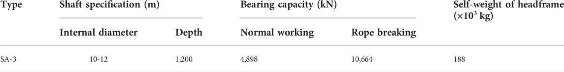
TABLE 1. Main parameters of the SA-3 shaft sinking headframe.
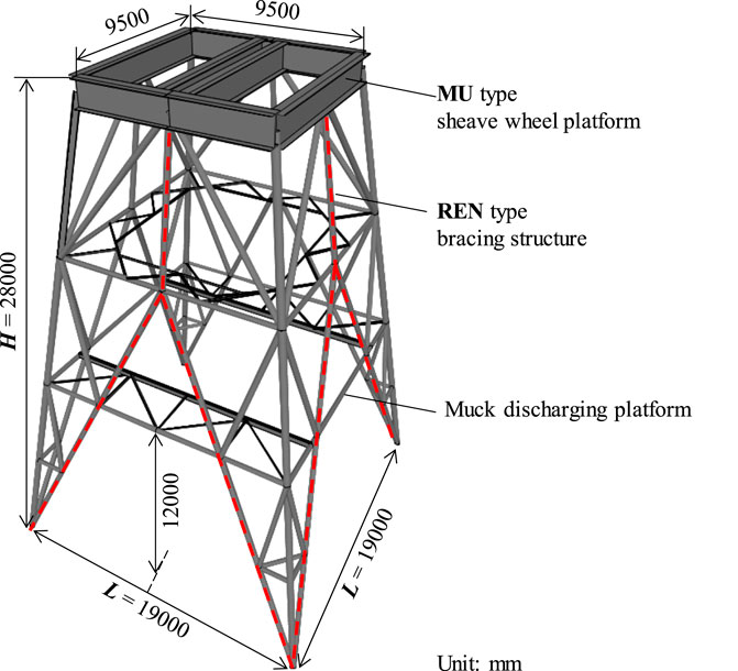
FIGURE 1. 3D sketch of the SA-3 shafts sinking headframe.
The SA-3 shaft sinking headframe adopts an MU type sheave wheel platform and an REN type bracing frame and achieves a maximum bearing capacity greater than 10,000 kN under the rope breaking condition. The height of the SA-3 shaft sinking headframe is 28 m, and sizes of the sheave wheel platform and bottom section of the SA-3 shaft sinking headframe are 9.5 and 19 m, respectively.
As shown in Figure 2, the sinking equipment on the SA-3 shaft sinking headframe mainly includes: four hoisting buckets (one double-hook hoisting and two single-hook hoisting), two central rotary muckers, a movable metal form (four wire ropes for suspending), a four-layer sinking platform (six wire ropes for suspending, four of them are used as guide ropes for the bucket), and a safety ladder, cables, pipes, etc.
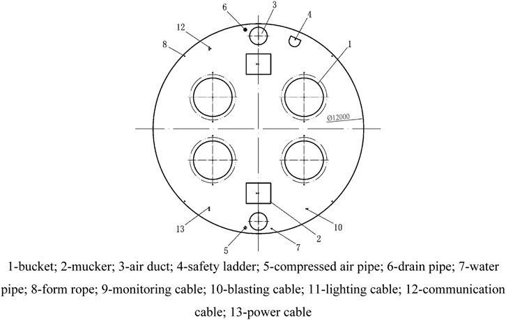
FIGURE 2. Layout of sinking equipment on the SA-3 shaft sinking headframe.
Loads acting on the shaft sinking headframe generally include permanent, variable, and special loads. Permanent loads refer to the self-weight of the shaft sinking headframe and sinking equipment. Variable loads refer to the loads that may change during shaft sinking, such as the working load of the hoisting wire rope, wind load, etc. Special loads refer to the breaking load of the hoisting wire rope, because the bucket is running at high speeds, and accidents, like jamming, serious over-winding, or cable slipping away from the sheave, are more likely to happen. In design, the following two load conditions shall be taken into consideration: the normal working condition and the rope breaking condition.
In the normal working conditions, the weight of the shaft sinking headframe and accessory equipment and the working loads of various hoisting and suspending ropes are included.
In the rope breaking condition, the considered loads include the weight of the shaft sinking headframe and accessory equipment, the breaking load of one hoisting rope, the double working load of the yoke rope, and the working load of the other ropes. In general, the partial factors of the permanent and variable loads are selected as 1.2 and 1.4 under normal working conditions and are selected as 1.0 under rope breaking conditions. The values of the loads under the working and rope breaking conditions are listed in Table 2. It can be seen that the total loads applied to the SA-3 shaft sinking headframe under normal working conditions and rope breading conditions are approximately 5,000 kN and 10,000 kN, respectively.
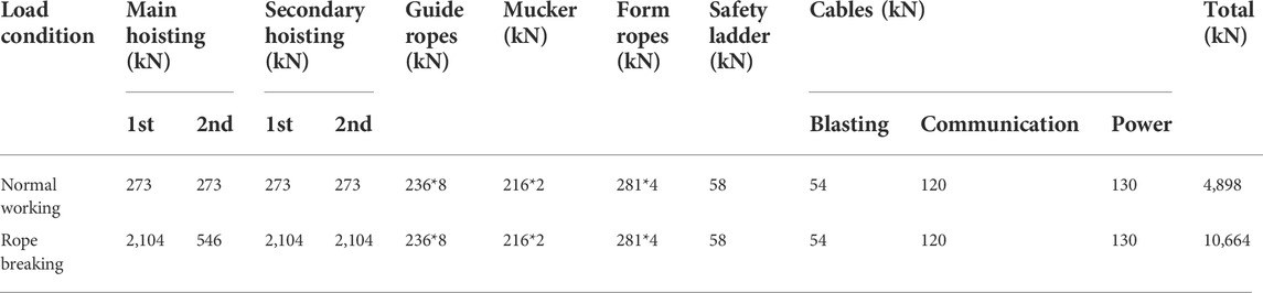
TABLE 2. Loads applied to the SA-3 shaft sinking headframe under normal working conditions.
Finite element analysis of the SA-3 shaft sinking headframe
The finite element (FE) analysis method is effective for evaluating the behavior and strength of the space steel pipe truss structure. In this paper, SAP 2000 was used to model the behavior of the SA-3 shaft sinking headframe subjected to uneven foundation settlement. As shown in Figure 3, a finite element model was built in accordance with the SA-3 structural design drawings. Sections of the boundary beam and middle beam on the sheave wheel platform were welded I-beams with dimensions of H1350 × 700 × 25 × 50 mm. Sections of the main bracing structure members are pipes with dimensions of ∅377 × 16 mm and ∅299 × 10 mm, respectively. The main beam on the muck discharging platform is double channels of ][36a. Because this study focuses on the behavior of the structural member, the connections between the members were not addressed. We assumed that the beam-to-beam joint and beam-to-corner post joint are rigid connections (red point shown in Figure 3) and other joints of the members are pinned for FE modeling. This assumption more properly presents the real structural behavior of the shaft sinking headframe. In SAP 2000, the pin connections of the members can be simulated by releasing one or more of the element degrees of freedom from the joint. For rigid connections, the three translational and three rotational degrees of freedom of the frame element are continuous. For pin connections, rotation at the end of the element should be released, and this assures that the moment is zero.
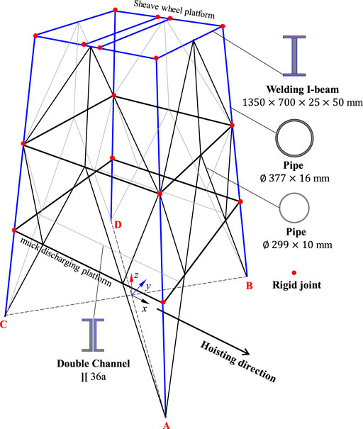
FIGURE 3. FE model of the SA-3 shaft sinking headframe.
In the FE analysis, only normal working conditions were considered. Based on the layout of the sinking equipment on the SA-3 shaft sinking headframe, loads under normal working conditions were applied to the FE model. Figure 4 shows the loads applied on the sheave wheel platform, each load was resolved into vertical and horizontal components at the connection of the secondary beam (for installation of hoisting and suspension sheaves) and applied to the FE model as a concentrated load. The weight of the members is calculated automatically by the program. The reliability of the FE model was verified by comparison with model test results in the structural design stage of the SA-3 shaft sinking headframe.
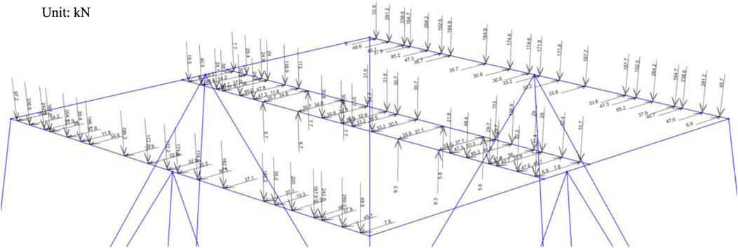
FIGURE 4. Loads applied on the sheave wheel platform under normal working condition.
Uneven foundation settlement of the SA-3 shaft sinking headframe
The foundation form of the shaft sinking four posts is independent of the foundation, and the settlement does not affect either. Therefore, there are various possible combinations of uneven settlement between the four post foundations, such as single, same-side, diagonal, double, and three-foundation settlement. According to the symmetrical characteristics of the bracing structure of the SA-3 shaft sinking headframe, the effect of three foundation settlements will be similar to a single foundation settlement, more specifically, it will be similar to the effect of single foundation uplift. The effect of same-side double foundation settlement is more likely to cause inclination and reduce the overall stability of the shaft sinking headframe. Referring to the standard for the design of mine headframes in China (GB 50385-2018), the allowable foundation deformation of mine headframes is as follows: for a single-diagonal-bracing steel headframe, the settlement difference between foundations should not exceed 0.001 L, in which L is the center-to-center spacing of the adjacent foundation; for a double-diagonal-bracing steel headframe, the settlement difference between foundations should not exceed 0.0005 L; and for both, the maximum settlement should be less than 80 mm.
Based on the above considerations, in this study, the following three combinations of uneven foundation settlements are discussed: Single, same-side, and diagonal double foundation settlement with a maximum uneven settlement of 160 mm. Details of the considered uneven foundation settlement combinations are shown in Figure 5 and Table 3.
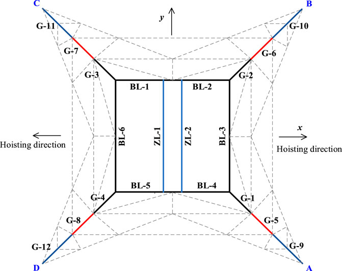
FIGURE 5. Diagram of uneven foundation settlement of the SA-3 shaft sinking headframe.
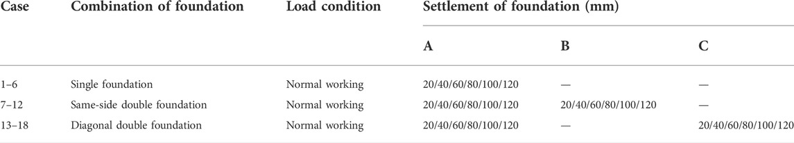
TABLE 3. Combinations of the uneven foundation settlement on the SA-3 shaft sinking headframe.
Results and analysis
Mechanical performance of the SA-3 subjected to uneven foundation settlement
Figure 6 shows the axial force diagram of members caused by the settlement of a single foundation A under normal working conditions. From the figure, it can be seen that the axial force of the members near foundations A and C was changed from compression to tension, whilst the members near foundations B and D were subjected to compression and their axial force increased as the foundation settlement increased.
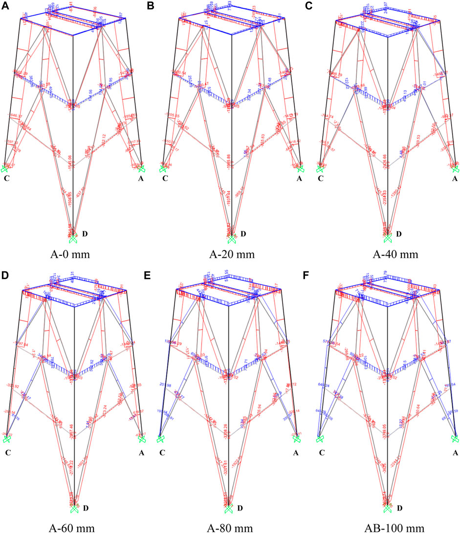
FIGURE 6. Axial force of the members versus the settlement of a single foundation A. (A) A-0 mm (B) A-20 mm (C) A-40 mm (D) A-60 mm (E) A-80 mm (F) AB-100 mm
The additional stress ratio (∆λtotal, which is the additional total stress ratio caused by uneven foundation settlement compared to the initial state of members under normal working conditions) of beams on the sheave wheel platform and total stress ratios (λtotal = λN+λMmaj+λMmin, in which λN is the axial stress ratio, λMmaj is the moment stress ratio in the principal axis direction, and λMmin is the moment stress ratio in the secondary axis direction) of the corner members are plotted in Figures 7, 8. Figure 7 shows that additional stress occurs in the middle beams, ZL-1 and ZL-2. The additional stress ratio is about 35% under a single foundation settlement of 20 mm (0.001 L = 19 mm), and approximately 141% under a diagonal double foundation settlement of 20 mm. In Figure 8, the results show that the axial force of the corner posts has essential variations under single foundation settlement and diagonal double foundation settlement. The states of the corner posts, G-5, G-9 (foundation A side), G-7, and G-11 (foundation C side), changed from compression to tension. In view of the total stress ratio, 60 mm of single foundation settlement (max. additional stress ratio is 51% in G-3) and 40 mm of diagonal double foundation settlement (max. additional stress ratio is 82% in G-2) are acceptable for the safety of the corner members.
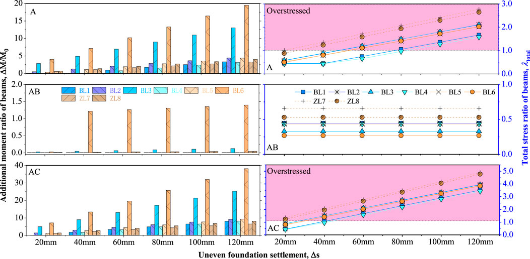
FIGURE 7. Additional stress of beams under uneven foundation settlement.
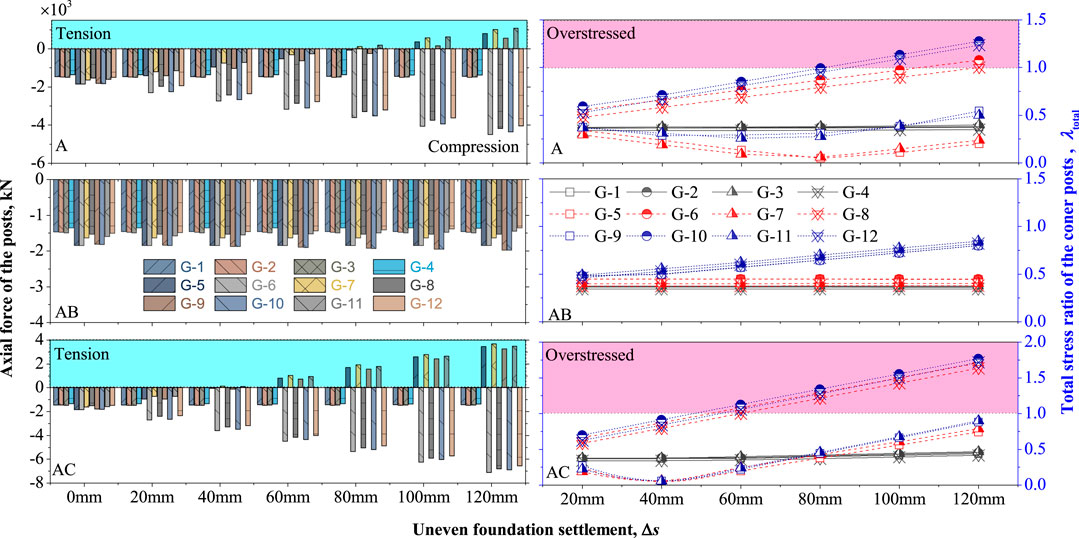
FIGURE 8. Axial force of the corner members under uneven foundation settlement.
Deformation behavior of the SA-3 subjected to uneven foundation settlement
Figure 9 shows the contours of the displacement of the deformed sheave wheel platform under various foundation settlements. The results show that the displacements were mainly toward the side of the settled foundation and increased as the uneven foundation settlement increased. At the maximum foundation settlement of 120 mm, displacements of the top corners reached 263 mm, 288 mm, and 175 mm under a combination of single A, double AB, and AC foundation settlement.
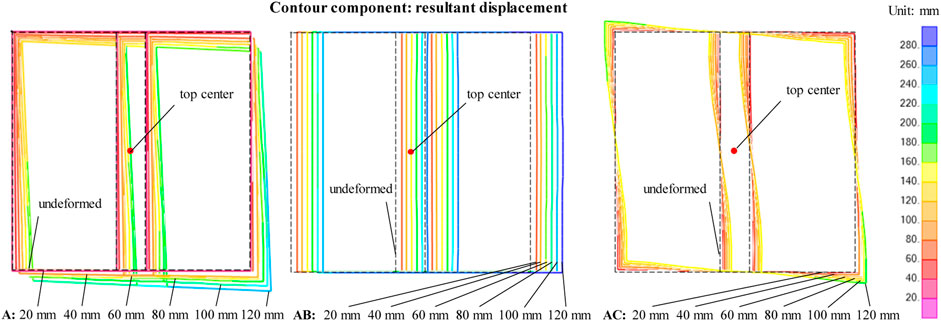
FIGURE 9. Contours of the deformed sheave wheel platform of the SA-3 shaft sinking headframe.
The ratio of the resultant displacement to the geometric offset is important in evaluating the ability of the shaft sinking headframe subjected to uneven foundation settlement. The geometric offsets at the top center position of the shaft sinking headframe can be approximately calculated according to the following formula:
Here ∆s is the settlement difference between foundations in mm; H is the top surface height of the sheave wheel platform; and L is the distance between the corner members at the bottom of the SA-3 shaft sinking headframe.
Figure 10 shows the analyzed displacement in the X-Y plane at the top center position of the SA-3 shaft sinking headframe by FE analysis. It can be seen that the resultant displacement in the X-Y plane occurred under the conditions of the same-side double and single foundation settlement. The displacement in the X-Y plane increased almost linearly with the foundation settlement. The ratios of the resultant displacement in the X-Y plane to the geometric offset were 2.0 and 2.8, respectively. There was no significant displacement in the X-Y plane at the top center of the SA-3 shaft sinking headframe under the condition of the diagonal double foundation settlement.
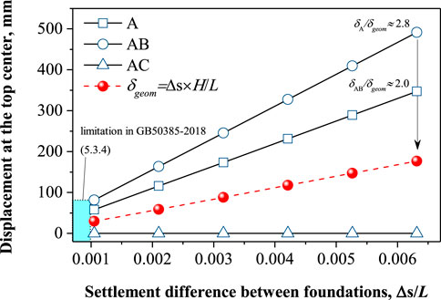
FIGURE 10. Axial force of the corner posts under uneven foundation settlement.
Discussion
As mentioned above, uneven foundation settlement can cause additional stress on members and geometric offset on sheaves, which affects the safety and service performance of the shaft sinking headframe. The accurate prediction of the adverse effects of uneven foundation settlement on shaft sinking headframe is of practical importance. In general, the total stress ratio of the members should be less than 1.0 (standard for designing steel structures: GB 50017-2017) and the distance between the sinking platform and the concrete shaft lining should not exceed 100 mm (code for construction of shaft and roadway of coal mine: GB 50511-2010). Therefore, determining the criteria of uneven foundation settlement should consider both the stress and deformation behavior of the shaft sinking headframe structure. Figure 11 plots the number of overstressed frames versus the uneven foundation settlement ratio (∆s/L). It shows that the numbers of overstressed frames under the foundation settlement of AC and A were larger, and the number of overstressed frames under the foundation settlement of AB was comparatively small. For safety considerations, the number of overstressed frames can be ignored when the uneven foundation settlement is less than 0.001 L. Meanwhile, as shown in Figure 10, displacement at the top center of the sheave wheel platform was less than 100 mm when the uneven foundation settlement was less than 0.001 L. This result is consistent with the standard for design of mine headframes (GB 50385-2018), which makes the result reliable and very useful in engineering practice. At present, although there are grouting reinforcement and rectification technologies to deal with the uneven foundation settlement under emergency conditions, we should pay more attention to geotechnical investigation and to prevent the uneven settlement of foundations.
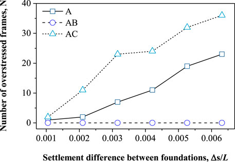
FIGURE 11. Axial force of the corner posts under uneven foundation settlement.
Conclusion
In this study, an FE analysis was performed to investigate the effects of uneven foundation settlement on the mechanical and deformation behavior of the shaft sinking headframe. The criterion of the shaft sinking headframe subjected to uneven foundation settlement was discussed. The main conclusions are as follows:
1) Uneven foundation settlement can cause additional stress of members and geometric offset of sheaves and affect the safety and service performance of the shaft sinking headframe. The most unfavorable condition for the stress of members is diagonal double foundation settlement. In contrast, the most unfavorable condition for the geometric offset of the structure is same-side double foundation settlement.
2) The axial force of the members near the settled foundation changed from compression to tension, whilst the members near the unsettled foundation were subjected to compression and their axial force increased as the uneven foundation settlement increased.
3) Displacement in the X-Y plane mostly occurred under conditions of same-side double and single foundation settlement. The displacement in the X-Y plane increased almost linearly with the uneven foundation settlement.
4) Acceptable uneven foundation settlement for the shaft sinking headframe can be determined as 0.001 L. This result is reliable and can be used for reference in engineering practice.
Data availability statement
The original contributions presented in the study are included in the article/Supplementary material; further inquiries can be directed to the corresponding author.
Author contributions
Data curation: SY; writing, original draft preparation: BW; writing, review, and editing: ZL.
Funding
This research was supported by the National Science Foundation of China (Grant Nos 51874286 and 51408595) and the Natural Science Foundation of Jiangsu Province of China (Grant No. BK20140203).
Acknowledgments
The authors gratefully appreciate the support.
Conflict of interest
The authors declare that the research was conducted in the absence of any commercial or financial relationships that could be construed as a potential conflict of interest.
Publisher’s note
All claims expressed in this article are solely those of the authors and do not necessarily represent those of their affiliated organizations, or those of the publisher, the editors, and the reviewers. Any product that may be evaluated in this article, or claim that may be made by its manufacturer, is not guaranteed or endorsed by the publisher.
References
Chen, H., and Shi, T. S. (1999). Research on experimental model of multirope hoisting steel headframe influenced by artificially frozen ground. J. China Univ. Min. Technol. 28, 574–577.
Chen, J. J. (2014). Study on the structure selection and mechanical properties of the large sinking headframe. Xuzhou: China University of Mining and Technology. [masters dissertation].
Dong, J., Deng, H. Z., Ma, X., Wang, Z. M., and Jiao, L. P. (2000). Nonlinear full process analysis of steel super structural damage due to uneven ground settlement. China Civ. Eng. J. 33, 101–106.
Hardy, M. (2019). “Seismic elastic behaviour of mine headframes,” in Proceedings of the 4th international conference on shaft design and construction (Toronto: The Canadian Institute of Mining, Metallurgy and Petroleum), 203–212.
Liu, B., Wang, W. M., and Chen, Z. D. (2005). Settlement analysis of permanent headframe of Liangbaosi auxiliary shaft. Mine Constr. Technol. 26, 36–39.
Liu, C., and Zheng, G. (2004). Analysis of the influence of ground unequal settlement on the structure with elastic support model method. J. Build. Struct. 25, 124–128.
Liu, Z. Q., Hong, B. Q., and Long, Z. Y. (2017). 60 years science and research achievements of Mine construction. Mine Constr. Technol. 38, 1–6.
Liu, Z. Q., Wang, B., Du, J. M., and Li, M. L. (2017). New mine shaft sinking headframe with single platform applied to construction of deep and large diameter mine shaft. Coal Sci. Technol. 45, 24–29.
Lu, Z. K., and Ma, Z. C. (2016). Influence of differential foundation settlement on steel headframe. Coal Eng. 48, 28–30.
Qi, H. G., and Pu, Y. N. (2013). Current situation and development trend of deep mine shaft construction technology. Mine Constr. Technol. 34, 4–7.
Shu, Q. J., Yuan, G. L., Huang, Z. H., and Ye, S. (2016). The behaviour of the power transmission tower subjected to horizontal support’s movements. Eng. Struct. 123, 166–180. doi:10.1016/j.engstruct.2016.05.027
Wang, B., Liu, Z. Q., and Du, J. M. (2019). “Design and application of new series of large shaft sinking headframe,” in Proceedings of the 4th international conference on shaft design and construction (Toronto: The Canadian Institute of Mining, Metallurgy and Petroleum), 399–405.
Wang, B., Liu, Z. Q., Du, J. M., Wang, S., and Fan, H. (2017). Design method of double platform sinking headframe of large mine shaft. Coal Sci. Technol. 45, 161–167.
Wang, J. F. (1988). Illustration books of shaft sinking engineering. 1st ed. Beijing: China Coal Communications) Industry Publishing Home.
Wang, P. (2018). The influence of various burst loads on the bearing capacity and stability of steel derrick. Xuzhou: China University of Mining and Technology. [masters dissertation].
Wang, P. Y. (2018). Development and prospect of construction technique for super-large diameter deep vertical shaft. Coal Eng. 50, 47–50.
Wang, S. H., You, C. A., Ma, Z. Z., Qiu, Y., and Lv, Y. X. (2012). Analysis on unequal settlement of auxiliary shaft tower in Xinli. Geotech. Investig. Surv. 2, 33–37.
Wu, Q. M. (2006). Study on the influence of frost heave on derrick foundation in freezing sinking.” [masters dissertation]. Huainan: Anhui University of Science and Technology.
Xiao, Q. F., Li, M., Chen, B. J., Wang, L., and Huang, F. C. (2009). Treatment of uneven foundation settlement of freezing shaft sinking headframe. Mine Constr. Technol. 30, 37–39.
Yang, R. S., and Chen, J. (2015). Development status and prospects of mine shaft construction equipment and technology. Mine Constr. Technol. 36, 1–4.
Keywords: shaft sinking headframe, uneven foundation settlement, FE analysis, mechanical behavior, deep mining
Citation: Wang B, Liu Z and Yuan S (2022) Behavior of large shaft sinking headframe subjected to uneven foundation settlement. Front. Earth Sci. 10:941126. doi: 10.3389/feart.2022.941126
Received: 11 May 2022; Accepted: 28 June 2022;
Published: 22 July 2022.
Edited by:
Shuren Wang, Henan Polytechnic University, ChinaCopyright © 2022 Wang, Liu and Yuan. This is an open-access article distributed under the terms of the Creative Commons Attribution License (CC BY). The use, distribution or reproduction in other forums is permitted, provided the original author(s) and the copyright owner(s) are credited and that the original publication in this journal is cited, in accordance with accepted academic practice. No use, distribution or reproduction is permitted which does not comply with these terms.
*Correspondence: Bo Wang, d2FuZ2JvMTk4M0BjdW10LmVkdS5jbg==