 Lian-Wei Ren1
 Peng-Fei He
- 1School of Civil Engineering, Henan Polytechnic University, Jiaozuo, China
- 2School of Surveying and Land Information Engineering, Henan Polytechnic University, Jiaozuo, China
- 3WSP Australia, Newcastle, NSW, Australia
- 4Taiyuan Design Research Institute for Coal Industry, Taiyuan, China
With the continuous improvement of infrastructure, some high-speed railway lines will inevitably cross the goaf ground, and there is less research on the safety of high-speed rail construction in goaf ground. To make a reasonable and accurate safety evaluation of the high-speed railway construction in the mine goaf ground, machine learning combined with numerical simulation is used to evaluate the safety depth of goaf under the impact of high-speed railway load. An optimal algorithm is selected among BP, RBF, and PSO-RBF neural networks based on the accuracy of the predicted height of a caving fracture zone. Numerical models for simulating high-speed railway founded on goaf are set up using the commercial software package FLAC3D, where factors such as subgrade height, train speed, and axle load are investigated in terms of train load disturbance depth and the extent of the caving fracture zone. The results indicate that the PSO-RBF neural network has an error of 2.76% in predicting the height of the caving fracture zone; the depth of train load disturbance is linearly related to the axle weight and roadbed height but is a sinusoidal function of the train speed. Based on the numerical simulation results, a formula for calculating the depth of train load disturbance is proposed, which provides a certain reference value for the construction of high-speed railways in the goaf ground.
1 Introduction
Stringent ground settlement criteria are required for construction and operation of high-speed railways. When high-speed railways cross goaf zones, the dynamic load generated by trains could destabilize the existing stable goaf, resulting in settlement and inclination of subgrade and endangering the driving safety of high-speed railways (Lei et al., 2013; Liang et al., 2016). The waste of land caused by mining activities has become an important issue restricting sustainable development (Bian et al., 2012; Yu et al., 2018) Taking Qinshui coalfield in Shanxi Province as an example, due to the goaf site area of nearly 3000 square kilometers formed by coal mining, the high-speed railway line inevitably passes through the goaf site. As shown in Figure 1, the built Tai-jiao section, Shi-tai section, and Tai-xi section and the Qing-Yin high-speed railway and Tai-yan high-speed railway under planning and research all pass through the goaf site.
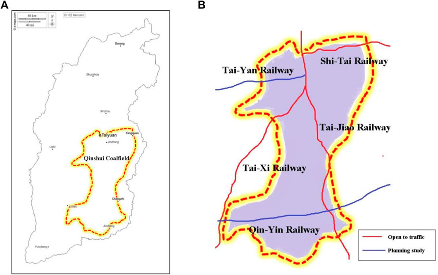
FIGURE 1. Study area: (A) Qinshui coalfield location in Shanxi Province, China; (B) high-speed railway line through Qinshui coalfield.
At present, domestic and international research is focused on the stability of goaf ground and stability under building loads (static loads). Guo et al. (2019) proposed an evaluation model of a goaf expressway with seven evaluation factors based on fuzzy theory, calculated the factor weight by gray correlation method, and applied the model to Wuyun Expressway to prove the reliability of the model. Liu et al. (2011) proposed a fuzzy matter-element model which used the AHP and matter-element extension method to identify the risk level of goaf zones. Maria et al. (2013) used the calculation method based on material resistance to analyze the sensitivity of goaf roof stability to the variation of roof material properties. Ashok et al. (2012) proposed a concept of panel stability based on Salamon stability (Merwe, 2003) criterion, which is further applied to analyze the critical failure modes of coal pillars. Debasis and Choi (2006) conducted sensitivity checks on various factors affecting the stability of aged goafs and used fuzzy collection theory to predict the occurrence probability of surface subsidence pits. Dong et al. (2008) proposed an evaluation index system based on uncertainty measure theory to predict the risk of goaf. Henry et al. (1989) summarized four mine collapse mechanisms, namely, single-force source, dual-force opposition, shear dislocation, and tensile force. However, there are fewer research results on the safety of high-speed railway construction at the goaf ground. Unlike other construction loads, high-speed railway loads are not only influenced by vehicle speed, roadbed height, and axle weight but also have the characteristics of strong periodicity and large changes. Once the activation and deformation of the extraction area by train load occurs, it will cause great hidden danger to the safety of high-speed railway traffic.
In this study, the machine learning method is used to predict the height of the caving fracture zone induced by construction and operation of high-speed railways. The numerical simulation method is used to obtain the train dynamic load disturbance depth under various working conditions by changing the embankment height, train speed, and train axle load. A calculation formula is provided to predict the train load disturbance depth, which can be combined with the caving fracture zone to evaluate the safety of foundations for high-speed railways.
2 Critical depth-to-thickness ratio of a high-speed railway goaf ground
2.1 Failure characteristics of overlay rock in coal mine goaf
Along with the coal seam being mined out, stress redistribution occurs in the goaf, and the original structure is destroyed. Upon completion of stress redistribution, a relatively stable mining-induced secondary rock structure is finally formed. The overlying strata can be divided into the caving zone, fracture zone, and bending zone, as shown in Figure 2A, after mining by the long arm caving method. The caving zone is mainly destroyed by the original overlying roof. The rock stratum breaks, and the caving fills the mining area. The caving zone is denser in the middle, but there are more cavities on the sides. The fracture zone induced by the bending of the rock layer is located above the caving zone. Different from the caving zone, the fracture zone maintains its layered structure and has more cracks in the rock layer. The bending zone mainly refers to the rock (soil) layer from the fracture zone to the surface. The vertical displacement of each rock layer in the bending zone is basically the same, though there are some separations and cracks. Masonry beam structures may also be present in the caving zone and fracture zone Figure 2B.
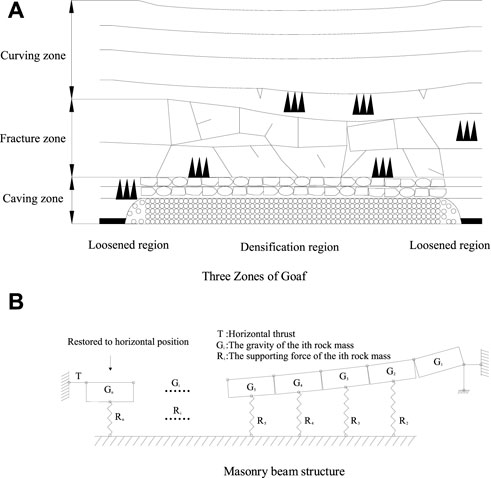
FIGURE 2. Characteristics of the mine goaf. (A) Three zones of goaf. (B) Masonry beam structure
2.2 Critical mining depth-to-thickness ratio
According to the overlay rock failure characteristics of goaf, the broken rock mass and cracks in goaf exist mostly in the caving zone and fracture zone. When the broken rock mass is compacted or the cracks are closed by external force, the goaf will be reactivated and deformed, resulting in surface subsidence and affecting the safety of surface buildings.
In general, the evaluation of the stability grade of the goaf site is based on the location of the depth of the additional stress influence and the depth of the caving fracture zone. Through numerical simulation, theoretical analysis, and model experiment, Zhang (2005) and Guo (2001) pointed out that the primary factor affecting the construction site of goaf should be the mining depth-to-thickness ratio. When the goaf site has a certain mining depth-to-thickness ratio, the existence of goaf has no effect on the foundation of buildings. Therefore, before traditional evaluation, it is necessary to preliminarily determine the mining depth–thickness ratio. If the condition is not met, the influence grade is divided by the relationship between the influence depth of additional stress and the depth of the caving fracture zone.
In order to determine the critical mining depth-to-thickness ratio, Zhang (2005) analyzed the simulation results of 12 calculation models and 144 calculation schemes and obtained the critical mining depth-to-thickness ratio under different loads and different action positions, as shown in Table 1 (building load).

TABLE 1. Determination of critical mining depth-to-thickness ratio of load.
Compared with the traditional building foundation, the high-speed railway engineering foundation has more strict requirements for settlement and inclination. When calculating the critical ratio in Table 1 (building load), due to the high degree of compaction and full filling in the middle area of the goaf, the safety factor is found to be 1.2. In the edge area, the structure similar to the masonry beam is formed after the rupture of the hard rock stratum. There are voids and uncompacted areas, and the safety factor is 1.5. In this study, the safety factor of the middle region is increased to 1.5, and that of the edge region is increased to 2.0. The criterion of the critical depth-to-thickness ratio of high-speed railway engineering is obtained (train load).
2.3 Load position
As shown in Figure 2B, the outer edge area mainly refers to the area from the open-off cut to the restoration level of the masonry beam rock block. The formula for calculating the length of this region can be obtained from the masonry beam theory (Qian, 1981):
where n is the number of rock blocks in the masonry beam structure, H is mining depth, φ is fully mining angle, Lz is the length of periodic weighting step distance, hi is the thickness of the key layer, ∑ hi is the thickness of the upper weak rock layer, σt is the ultimate tensile stress of the key layer, γ is the volumetric force of the rock layer, and L is the length of the outer edge region.
The inner edge area refers to the area where the rock block restores the horizontal position to the stop line. The compactness of the inner edge area is better than that of the outer edge area. For safety, Eqs 1–3 are also adopted for regional determination.
The compaction area is located in the middle of the inner and outer edge areas. Due to sufficient collapse of rock mass, there are fewer cracks in this area and the safety is high.
2.4 Foundation base load
The calculation of load mainly comprises static load of subgrade and dynamic load of a train. Liang and Cai (1999) proposed a sine function formula of train load considering geometric irregularity, which comprises single-wheel static load and dynamic load caused by geometric irregularity. The value of irregularity is shown in Table 2.
where P0 is the single-wheel static load, kN; ωi is circular frequency under various conditions; m0 is unsprung mass, kg; ai is arch rise under various conditions, mm; V is train speed, m/s; and Li is wave-lengths under various conditions, m.
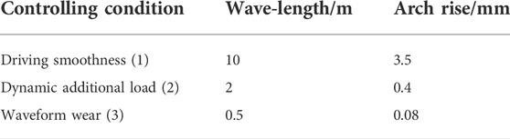
TABLE 2. Irregularity selection.
Based on the measured data of dynamic stress attenuation law, Bian et al. (2010) obtained the attenuation formula of subgrade dynamic stress:
where z is the subgrade height, a and b are the fitting coefficients, and the mean values of the fitting coefficients a and b of ballasted track are 0.64 and 0.86, respectively.
In summary, the calculation formula of the base load can be obtained:
where γi is the bulk density of the subgrade material for layer i, zi is height of the subgrade material of layer i, and W is the foundation base width.
3 Influence degree of goaf ground activation
When the critical depth-to-thickness ratio of the goaf site does not meet the standards given in Table 1, the influence degree of reactivation needs to be determined. The additional load distributed from the foundation of any structures above, once its value is no more than 10% of the weight of the overburden rock-soil mass, is considered to impose no significant effect on the rock and soil mass at this depth. Due to a stringent requirement for subgrade settlement for the construction and operation of high-speed railways, a critical influence depth of train load, Ha, is defined as the disturbance depth at which the distributed additional stress from the train load is 5% of the weight of rock and soil above.
The relationship between the critical influence depth of train load and the depth position of the caving fracture zone is depicted in Figure 3.
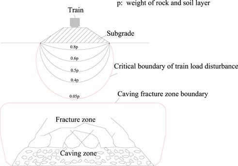
FIGURE 3. Interaction between high-speed railway and the mining zone.
Because of strict requirements for high-speed railway ground deformation, the more stringent evaluation criteria should be adopted after considering China code’s criteria (The Professional Standards Compilation Group of People’s Republic of China, 2014): 1) when the buried depth of the caving fracture zone is greater than or equal to 2.5 times the load influence depth, the influence is little; 2) when the buried depth of the caving fracture zone is less than 2.5 times the load influence depth and greater than or equal to the load influence depth, the influence is moderate; 3) when the buried depth of the caving fracture zone is less than the load influence depth, the influence is great.
4 Height prediction of the caving fracture zone
This study compares the depth of train load disturbance (Ha) and the depth of the caving fracture zone (Hlf) to determine the “re-activation” of the goaf ground. Prediction of the height of the caving fracture zone is commonly based on the empirical formula in GB 51044 (2014). This method is relatively straight-forward, but it will produce a less accurate prediction of the safety depth of the goaf ground for considering only the coal seam mining thickness.
Machine learning, as an objective and effective prediction variable or classification method, has been widely used in geotechnical engineering (Tan et al., 2011; Cai et al., 2020; Mahmoodzadeh et al., 2021). There are many factors affecting the development height of the caving fracture zone. As such, a reasonable influencing factor system is critical for a more accurate prediction based on the machine learning method. As per Guo et al. (2021), seven factors are selected in this study: overburden structure, buried depth, dip angle, mining thickness, working face size, coal mining method and layered mining number. Thirty-eight sets of data as provided in Wang et al. (2016) are adopted to train and test samples, which are listed in Table 3.
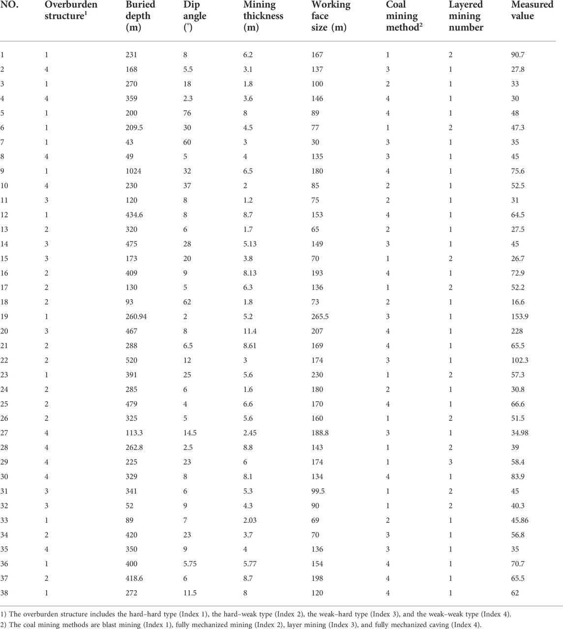
TABLE 3. Learning samples.
4.1 Introduction of machine learning methods
The back-propagation (BP) neural network is a widely used neural network trained according to the error back-propagation algorithm. The BP neural network adopts the gradient descent method, but which tends to terminate the learning by only achieving a local optimal value. As such, the prediction accuracy of using a BP neural network is not high.
The RBF neural network is a feedforward nonlinear neural network. The RBF (radial basis function) neural network consists of three layers, namely, the input layer, hidden layer and output layer. The radial basis function of multivariable nonlinear interpolation is adopted to transfer the input layer data to the hidden layer instead of the “weight” function used in the BP neural network. A linear interpolation is adopted in the RBF neural network when the hidden layer outputs to the output layer. In this way, the mapping of the network from input to output is nonlinear, but the network output is linear for variables. The “weight” factor of the network can be directly solved based on a set of linear equations. In this study, the RBF neural network algorithm is further combined with the PSO-RBF-neural network algorithm (Qin et al., 2005) for learning, and the results are compared with those based on the BP neural network. The optimal algorithm is then selected in order to overcome the local convergence issue of the BP neural network.
4.2 Error analysis and selection
According to the results of sample training and testing, the performance diagrams of each algorithm are provided in Figure 4. The PSO-RBF algorithm is found to provide the highest fitting degree.
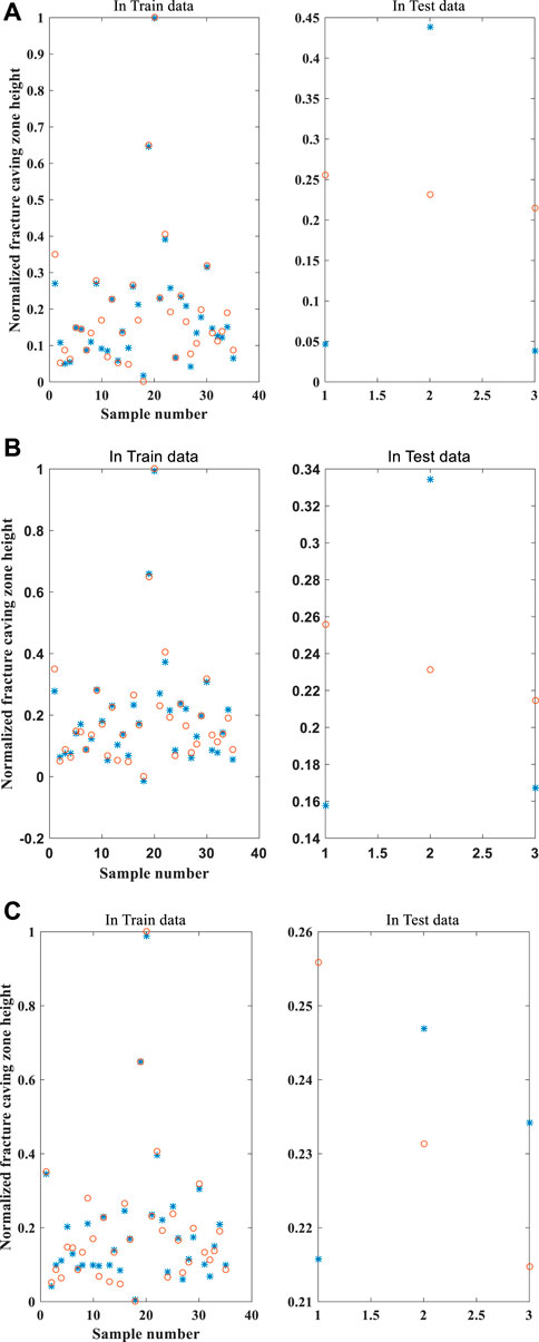
FIGURE 4. Neural network fitting results: (A) BP neural network fitting results; (B) RBF neural network fitting results; (C) RBF-BP neural network fitting results.
Equation 9 is adopted to calculate the error between the training set and the testing set for each algorithm mentioned above:
where E is error of the training set or testing set, ypi is the ith predicted value, yi is the ith measured value and n is the total number of objects in the set.
The results in terms of the error of the training set and test set based on Eq. 9 are provided in Table 5. It shows that some algorithms have a high fitting degree on the training set but a low fitting degree on the test set. This might be attributed to a relatively small number of samples (38 groups). A comprehensive error is thus defined in Eq. 10:
where Es is composite error, Etrain is the error of the training set, and Etest is the error of the test set.
The calculation of Eq. 10 shows that in the case of the same training samples and test samples, the PSO-RBF neural network algorithm provides a minimum comprehensive error of 2.76%, while the RBF and BP neural network algorithms provide 8.048% and 12.84%. The PSO-RBF neural network algorithm performs even better than the GA-BP prediction model (2016) and thus will be used to predict the height of the caving fracture zone.
5 Numerical simulation of train load disturbance depth
A lot of research works have been carried out to investigate the dynamic response of soil under the influence of train load. Xia et al. (2009) proposed a coupling model to simulate the train–track–soil dynamic response by considering the track irregularity condition and the vibration induced by track irregularity. Galvin and Dominguez (2009, 2010a, 2010b) established the train–track–subgrade finite element model to analyze the dynamic response of three typical tracks under train load.
As a commonly used numerical analysis software in geotechnical engineering, FLAC3D is widely used in slope stability (Zhou and Qin, 2020), mining engineering (Booth et al., 2016), and geotechnical engineering (Yang et al., 2020). To accurately obtain the depth of ground disturbance under train load, FLAC3D software is used to simulate this study.
5.1 Prediction of disturbance depth
5.1.1 Train load simulation
Lamaran and Derdas (2002) simulated the load as the sum of the static load and additional dynamic load as a function of train speed, sleeper spacing, rail properties, and wheel weight. Auke and Gerard (2001) pointed out that the geometric irregularity caused by rail wear will produce huge wheel–rail impact force. Manabe (2004) studied the rail vibration caused by multiple wheelsets under track irregularity. Various geometric irregularities can also contribute to the variation of the train dynamic load magnitude (Jenkins et al., 1974). At present, the commonly used train load simulation formula is composed of a series of sine functions. In this study, the sine function of Eq. 4 considering irregularity is taken as the function of simulating train load.
5.1.2 High-speed railway subgrade–foundation model
According to the geotechnical engineering investigation results of the research railway section, the subgrade–foundation structure model is established as shown in Figure 5.
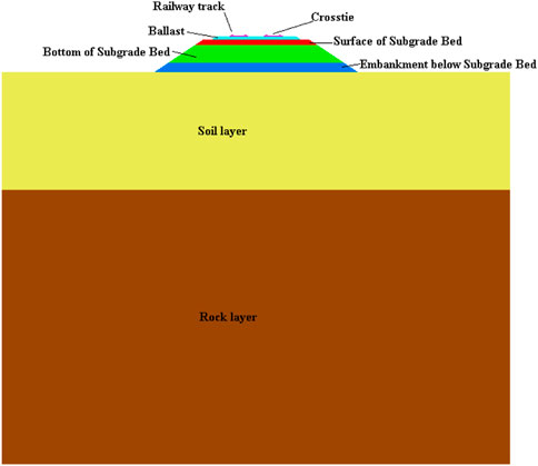
FIGURE 5. Train foundation structure.
The length of the model is 64.8 m, and the height is 55 m.
5.1.3 Constitutive model and parameters
The British Derby Railway Research Center indicates that the dynamic behavior of a traditional ballast track subgrade is similar to that of an elastic damping material. In this study, a Mohr–Coulomb constitutive model is used for the rock and soil layer, and an elastic constitutive model is used for subgrade structure. The material parameters of each layer are shown in Table 4.
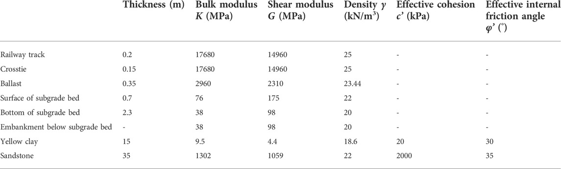
TABLE 4. Parameters of subgrade and soil layers.
5.1.4 Boundary condition and damping
A viscous boundary condition is adopted in FLAC3D to absorb the vibration wave and improve the calculation efficiency. Rayleigh damping is selected in this study, with a damping ratio parameter of 0.5%.
5.1.5 Model validation
The numerical model is first validated against the monitoring data obtained from the Qinhuangdao–Shenyang passenger line (Nie, 2005). The dynamic stress at the bottom of the foundation bed predicted in this numerical simulation and the measured values are provided in Figure 6. It can be seen that the numerical model can capture the upper bound and lower bound values for the dynamic stress and the variation period. It can be seen from Figure 6 that the simulated dynamic stress value changes faster than the measured value because the simulated dynamic stress considers the geometric irregularity. When the train runs several times, it will be partially worn, which makes the train travel on the railway similar to a jumping state. The measured value is measured when the railway has just been built and the track is relatively smooth.
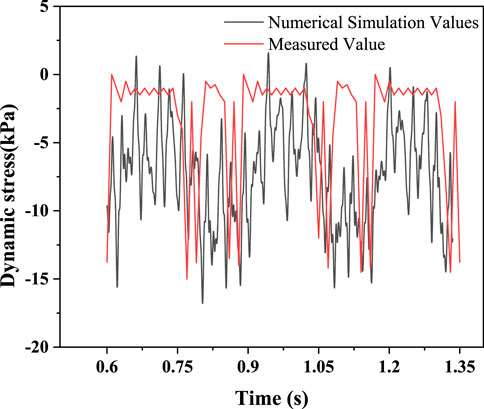
FIGURE 6. Model verification.
5.2 Disturbance depth formula
In this study, FLAC3D software is used to simulate the depth of train load disturbance as a function of axle load, speed, and embankment height, and twelve groups of models are designed by control variables as shown in Table 5. The depth of load disturbance was determined by comparing the maximum additional stress at each monitoring point with the 5% self-weight of the rock and soil mass at the point.
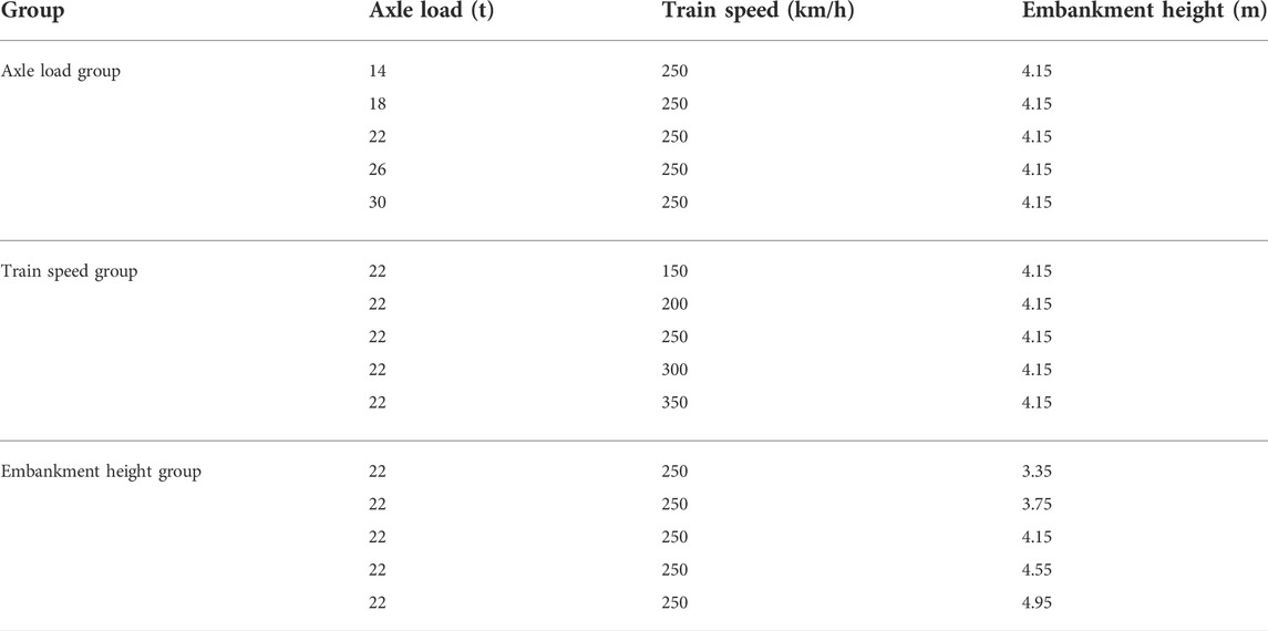
TABLE 5. Experimental groups.
When two high-speed trains meet at the goaf ground, the load on the goaf ground is the largest. In order to accurately determine the disturbance depth of train load, stress monitoring points are set between the single rail and double rail in the same numerical model so as to determine the location of the maximum disturbance depth. The results are shown in Figure 7.
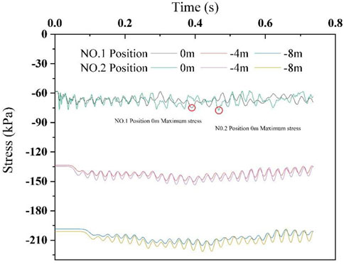
FIGURE 7. Load size under different action positions.
At −4 and −8 m, the load of the monitoring points between the double track is always greater than that between the single track. At 0 m, the load fluctuates greatly, but it is still the maximum value of the monitoring points between the double track. So, the position between the two tracks is selected to arrange monitoring points for determining the maximum disturbance depth. The diagram of stress change and disturbance depth for each group is shown in Figure 8.
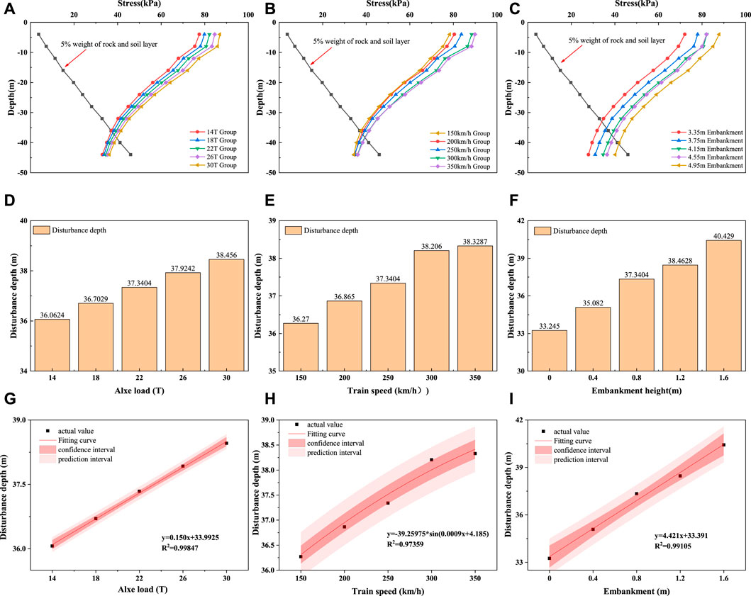
FIGURE 8. (A) Relationship between influence depth of dynamic load and axle load; (B) relationship between dynamic load influence depth and velocity; (C) relationship between dynamic load influence depth and embankment height; (D) disturbance depth under different axial loads; (E) disturbance depth under different train speeds; (F) disturbance depth under different embankment heights; (G) fitting of axle load and disturbance depth; (H) fitting of train speed and disturbance depth; (I) fitting of embankment height and disturbance depth.
5.2.1 Influence analysis of train axle load
In this study, the influence depth under the five grades of axle load listed in Table 5 is studied. As shown in Figures 8A,D, the increase of axle load would increase the additional dynamic stress on the base and increases the influence depth significantly. This is because the axle load directly affects the unilateral static wheel load, and the size of the unilateral static wheel load accounts for a large proportion of the dynamic load (see Eq. 4).
5.2.2 Influence analysis of train speed
Five grades of varying train speed between 150 and 350 km/h, as listed in Table 5, are used to study the change of dynamic load influence depth. It can be seen from Eq. 4 that the increase of train speed would result in a corresponding increase in the force acting on the rail, which should be attributed to the impact of the change of speed on the circular frequency under various control conditions. The influence depth, as indicated in Figure 8B, is observed to increase linearly with the train speed increases from 150 to 300 km/h but remains nearly constant when the train speed increases from 300 to 350 km/h. This observation is consistent with the findings of Bian et al. (2014). Such impacts of train speed on influence depth should be attributed to a shorter duration of train load with the train speed increasing.
5.2.3 Influence analysis of embankment height
Five groups of embankment height, namely, 3.35 m, 3.75 m, 4.15 m, 4.55 m, and 4.95 m are studied regarding their influence on the depth of train dynamic load. As shown in Figures 8C,F, with the increase of embankment height, the static load imposed on the foundation by the embankment would increase, which, thereby, would increase the influence depth of train load. In fact, due to the characteristics of high-speed rail, dozens of high-speed railway will pass through every day, and increasing the embankment height can effectively reduce the impact of dynamic load on the site. For example, the curve of 4.15 and 4.55 m embankments in Figure 8C shows that the additional load under the condition of 4.15 m is basically the same as that under the condition of 4.55 m at the monitoring point of 4 m below the base. Although the static load of the 4.55 m embankment is larger than that of the 4.15 m embankment, the increase of embankment height makes the disturbance consumption of train dynamic load increase, resulting in the additional stress being equal at the base of 4 m.
5.2.4 Disturbance depth of train load
Figures 8A–F show that the disturbance depth is dependent on the additional stress, the latter of which is a function of the axle load, train speed, and embankment height. These three factors are mutually independent. As such, the relationship between the disturbance depth and each factor can be obtained by data fitting. A comprehensive formula by superposition can be obtained for the critical disturbance depth of train load.
The fitting results of the relationship between the three factors and disturbance depth are shown in Figures 8G–I. A linear relationship is apparent between the two factors of axle load and embankment height and the disturbance depth. A sine function relationship is, however, observed between the train speed and disturbance depth, which should be attributed to the loading function (a sine function, Eq. 4) used in this study.
As shown in Eq. 11, the relationship between the critical disturbance depth of train dynamic load and the three factors, i.e., axle load, speed and embankment height can be obtained as
where Hd is the critical disturbance depth of train dynamic load, m; G is axle load, ton; H is height of embankment below subgrade bed, m; v is train speed, km/h; and a0, a1, a2, and a3 are fitting coefficients.
By using a multiple linear regression analysis, the following values for the fitting coefficients can be obtained:
Substituting a0, a1, a2, and a3 into Eq.11, the formula for calculating the critical depth of train dynamic load disturbance is shown in Eq.12.
The residuals obtained by this multiple linear regression are shown in Figure 9. The confidence interval of residual values at each data point contains 0 points, and the R2 value of this formula is 0.97, indicating that this fitting can better reflect the original data.
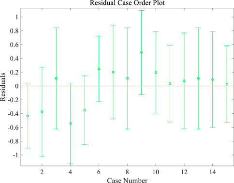
FIGURE 9. Fitting residual error.
6 Case study
6.1 Engineering geology
In order to verify the validity of the judgment method and the correctness of the FLAC3D model, an engineering example, DK259 + 690-DK259 + 710 road section of Tai-Jiao high-speed railway, as shown in Figure 10, is used to verify the approach provided above. The high-speed rail line crosses No. 2 goaf, which has a buried depth of goaf about 46.6 m and a maximum mining height of about 6.5 m. The dip angle of the coal seam is 2°–5° and was mined by blast mining. The backfilling material is sandstone and mudstone gravels, and the backfilling structure is loose. The high-speed railway is constructed with ballast track, and the height of the embankment below the subgrade bed is 0 m. The ground profile and the design parameters are the same as those adopted in this study above (Figure 6 and Table 4). The design train speed is 250 km/h, the design axle load is 22 t, and the railway trunk line is 40 m from open-off cut.
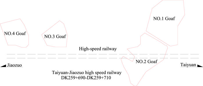
FIGURE 10. Engineering location.
6.2 Critical mining depth-to-thickness ratio determination
The goaf site of the railway trunk line is determined according to Eqs 1–3, and relevant data are inserted: hi is 3 m, Σhi is 10 m, γ is 2.5e4 N/m3, σt is 10 MPa, and H is 46.6 m. The calculation shows that Lz is 9 m and n is 5. The length of the outer edge and inner edge is 45 m. Therefore, the location of the high-speed railway project is the outer edge area.
The mining depth-to-thickness ratio of the goaf site is only 7, which does not meet the critical value of any working condition in Table 1. Therefore, the relationship between the depth of the caving fracture zone and the disturbance depth is used to determine the influence level of goaf activation.
6.3 Height prediction of the caving fracture zone
The height of the caving fracture zone in the goaf is predicted by the PSO-RBF algorithm. The engineering condition of the goaf is normalized and compiled, with an input matrix being obtained:
The trained grid is used to train the input matrix, and the height of the caving fracture zone in the goaf is calculated to be 39.37 m.
6.4 Train load disturbance depth prediction
To verify numerical simulation and Eq.12, these two methods are compared by predicting the disturbance depth of the train dynamic load.
The numerical simulation model produces the Z direction stress figure. As shown in Figure 11, the influence depth under this condition is 32.96 m. At the same time, the numerical simulation model results show that the maximum stress load at 0 m is 72.56 kPa, and the result obtained by Eq. 8 is 80.682 kPa, indicating that the equation is reasonable.
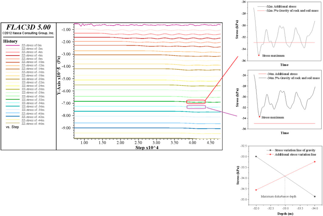
FIGURE 11. Z-Direction stress map.
With the train parameters substituted into Eq. 12, the dynamic load disturbance depth is predicted to be 33.675 m. The difference between the values predicted by these two methods is only 0.679 m.
Calculations of the height of the caving fracture zone and the depth of train load disturbance show that the critical disturbance boundary of the train dynamic load is expected to intrude into the top boundary of the caving fracture zone. The dynamic load of the train would impact the caving fracture zone, closure of the separation layer and cracks, and reactivate goaf deformation. The influence level of the goaf site is significant.
Grouting treatment was carried out during the construction of high-speed railway in this section to fill the separation layer and cracks in the caving fracture zone to improve the foundation performance. This is consistent with the predicted results of the research method and indicates that the method has some engineering reference value.
7 Conclusion
Due to the high-intensity and long-term mining of China’s coal resources, a large area of goaf sites have been formed. In addition, with the rapid development of high-speed railway, some key lines will inevitably cross the coal mine goaf site. The activation evaluation criteria of goaf ground are one of the urgent problems to be solved to ensure the safe operation and maintenance of high-speed railways. Based on the neural network and numerical simulation, the combined methods for the goaf ground activation criteria of high-speed railway are proposed. The main conclusions are as follows:
1) The criteria for determining the critical mining depth-to-thickness ratio of high-speed railway in the goaf site is given, the zoning formula of the goaf site is proposed, and the simplified formula of combined action under subgrade and train load is obtained.
2) The BP, RBF, and PSO-RBF neural networks are used to learn the 38 mine goaf samples, and the error of each model for sample learning and testing is obtained. The PSO-RBF neural network model has the lowest error, which can be used to predict the height of the caving fracture zone in the goaf site.
3) One evaluation criterion for the influence degree of goaf ground stability of high-speed railway is proposed, and a simple and effective numerical simulation model about applying train dynamic load is established. Comparisons on the additional dynamic stress and self-weight stress of the goaf ground are drawn, the disturbance depth of train dynamic load is predicted, and the influence degree of goaf ground stability is judged.
4) Activation judging formula with high availability and reliability is deduced. By changing the embankment height, train speed, and train axle load, the FLAC3D model was used to simulate various working conditions. The results show that the disturbance depth of train dynamic load has a good functional relationship with the abovementioned three factors. The calculation formula of critical depth of train dynamic load disturbance is given by using the superposition principle and multiple linear regression analysis.
5) An example verification process through a line section of the Taijiao high-speed railway proves that the method has a certain reference value in the safety evaluation of high-speed railway construction projects at the site of the mining area, but it cannot provide detailed hazard classification, such as the corresponding measures to be taken for each level of hazard.
Data availability statement
The original contributions presented in the study are included in the article/Supplementary Material; further inquiries can be directed to the corresponding author.
Author contributions
LR: Conceptualization, Methodology, Software, Investigation, Formal Analysis; PH: Data Curation, Writing–Original Draft, YZ: Visualization, Investigation; CY: Resources, Supervision; ZD: Software, Validation; ZZ: Visualization, Writing–Review & Editing; CS: Numerical model modification and debugging.
Funding
Funding for this work was supported by the National Natural Science Foundation of China (No. U1810203).
Conflict of interest
Author CY is employed by WSP Australia and Author CS is employed by Taiyuan Design Research Institute for Coal Industry.
The remaining authors declare that the research was conducted in the absence of any commercial or financial relationships that could be construed as a potential conflict of interest.
Publisher’s note
All claims expressed in this article are solely those of the authors and do not necessarily represent those of their affiliated organizations, or those of the publisher, the editors, and the reviewers. Any product that may be evaluated in this article, or claim that may be made by its manufacturer, is not guaranteed or endorsed by the publisher.
References
Ashok, J., and Shrivastva, B. K. (2012). Stability analysis of the proposed hybrid method of partial extraction for underground coal mining. Int. J. Rock Mech. Min. Sci. 52, 103–111. doi:10.1016/j.ijrmms.2012.03.002
Auke, D., Herman, G., and Holscher, P. (2001). Elastic Waves Gene rated by high-speed trains[J]. J. Comp. Acous. 9 (3), 833–840. doi:10.1142/s0218396x01001133
Bian, X. C., Jiang, H. G., Cheng, C., Chen, Y. M., Chen, R. P., and Jiang, J. (2014). Full-scale model testing on a ballastless high-speed railway under simulated train moving loads. Soil Dyn. Earthq. Eng. 66 (11), 368–384. doi:10.1016/j.soildyn.2014.08.003
Bian, X. C., Jiang, H. G., and Chen, Y. M. (2010). Accumulative deformation in railway track induced by high-speed traffic loading of the trains. Earthq. Eng. Eng. Vib. 9 (3), 319–326. doi:10.1007/s11803-010-0016-2
Bian, Z. F., Miao, X. X., Lei, S. G., Chen, S. E., Wang, W. F., and Sruthers, Sue (2012). The challenges of reusing mining and mineral-processing wastes. Science 337, 702–703. doi:10.1126/science.1224757
Booth Andrew, J., Marshall Alec, M., and Ro, S. (2016). Probabilistic analysis of a coal mine roadway including correlation control between model input parameters. Comput. geotechnics. 74 (4), 151–162. doi:10.1016/j.compgeo.2016.01.008
Cai, B., Pan, G. L., and Fu, F. (2020). Prediction of the postfire flexural capacity of rc beam using GA-BPNN machine learning. J. Perform. Constr. Facil. 34 (6). doi:10.1061/(ASCE)CF.1943-5509.0001514
Deb, D., and Choi, S. O. (2006). Analysis of sinkhole occurrences over abandoned mines using fuzzy reasoning: A case study. Geotech. Geol. Eng. (Dordr). 24 (5), 1243–1258. doi:10.1007/s10706-005-1404-7
Dong, L. J., Peng, G. J., Fu, Y. H., Bai, Y. F., and Liu, Y. F. (2008). Unascertained measurement classifying model of goaf collapse prediction. J. Coal Sci. Eng. China. 14 (2), 221–224. doi:10.1007/s12404-008-0046-9
Galvin, P., Romero, A., and Dominguez, J. (2009). Experimental and numerical analyses of vibrations induced by high-speed trains on the Córdoba–Málaga line. Soil Dyn. Earthq. Eng. 29 (4), 641–657. doi:10.1016/j.soildyn.2008.07.001
Galvin, P., Romero, A., and Dominguez, J. (2010a). Fully three-dimensional analysis of high-speed train–track–soil-structure dynamic interaction. J. Sound Vib. 329 (24), 5147–5163. doi:10.1016/j.jsv.2010.06.016
Galvin, P., Romero, A., and Dominguez, J. (2010b). Vibrations induced by HST passage on ballast and non-ballast tracks. Soil Dyn. Earthq. Eng. 30 (9), 862–873. doi:10.1016/j.soildyn.2010.02.004
Guo, G. L. (2001). Deformation mechanism and control of building foundation above old goaf[M]. Xuzhou: China University of Mining and Technology press. (in Chinese).
Guo, Q., Li, Y., Meng, X. R., Guo, G. L., and Lv, X. (2019). Instability risk assessment of expressway construction site above an abandoned goaf: A case study in China. Environ. Earth Sci. 78 (20), 588. doi:10.1007/s12665-019-8599-z
Guo, Q. B., Meng, X. R., Li, Y. M., Lv, X., and Liu, C. (2021). A prediction model for the surface residual subsidence in an abandoned goaf for sustainable development of resource-exhausted cities. J. Clean. Prod. 2021, 123803. doi:10.1016/j.jclepro.2020.123803
Henry, S. H., Wetmiller, R. J., and Gendzwill, D. J. (1989). Don J.gendzwill. Induced seismicity in mines in Canada—an overview[J]. Pure Appl. Geophys. 129 (3), 423–453. doi:10.1007/BF00874518
J enkins, H. H., Stephenson, J. E., Clayton, G. A., Morland, G. W., and Lyon, D. (1974). The effect of track and vehicle parameters on wheel/rail vertical dynamic loads[J]. J. Railw. Eng. Soc. 3 (1), 2–16.
Lamaran, G., and Derdas, M. (2002). Evaluation of dynamic load on rail track sleepers used on vehicle-track modeling and analysis[J]. Int. J. Struct. Stab. Dyn. 2 (3), 355–374.
Lei, S., Cui, Z., Zhang, H., and Han, L. (2013). Analysis and treatment of the fault activation below the dynamic foundation in the goaf area[J]. Disaster Adv. 6, 337–342.
Liang, B., and Cai, Y. (1999). Dynamic analysis on subgrade of high-speed railways in geometric irregular condition[J]. J. China Railw. Soc. 1999 (02), 93–97. (in Chinese).
Liang, X., Cheng, Q., Wu, J. J., and Chen, J. (2016). Model test of the group piles foundation of a high-speed railway bridge in mined-out area. Front. Struct. Civ. Eng. 10 (4), 488–498. doi:10.1007/s11709-016-0338-x
Liu, W. S., Li, F. Y., and Guo, X. T. (2011). “Comprehensive evaluation of the stability of coal mining subsidence based on fuzzy matter-element Theory[C],” in Natural resources and sustainable development. Part 1 (Freienbach, Switzerland: Trans Tech Publications), 237–241.
Mahmoodzadeh, A., Mohammadi, M., Ibrahim, H., Abdulharmid, S. N., Ali, H. F. H., Farid Hama Ali, H., et al. (2021). Artificial intelligence forecasting models of uniaxial compressive strength. Transp. Geotech. 27, 100499. doi:10.1016/j.trgeo.2020.100499
Manabe, K. (2004). Multiple-wheel induced vibration of rail with surface irregularity. QR. RTRI. 45 (3), 136–141. doi:10.2219/rtriqr.45.136
María-Belén, P. G., Alcalde-Gonzalo, J., Ramírez-Oyanguren, P., and Francisco-José Suárez-Domínguezálvarez-Fernández, M. I. (2013). Longwall mining stability in take-off phase. J. Appl. Math. 2013 (5), 859803–859813. doi:10.1155/2013/859803
Merwe, J. (2003). New pillar strength formula for South African coal[J]. Journal- South Afr. Inst. Min. Metallurgy. 103 (5), 281–292.
Nie, Z. H. (2005). Study on vertical dynamic response of the track/subgrade in high-speed railway[D]. Changsha, China: Central South University. (in Chinese).
Qian, M. G. (1981). A study of the behaviour of overlying strata in longwall mining and its application to strata control[J]. Dev. Geotechnical Eng. 32, 13–17.
Qin, Z., Chen, J., Liu, Y., and Lu, J. (2005). “Evolving RBF neural networks for pattern classification[C],” in International Conference on Computational & Information Science. (Berlin Heidelberg: Springer).
Tan, X. H., Bi, W. H., Hou, X. H., and Wang, W. (2011). Reliability analysis using radial basis function networks and support vector machines. Comput. Geotechnics. 38 (2), 178–186. doi:10.1016/j.compgeo.2010.11.002
The Professional Standards Compilation Group of People's Republic of China (2014). Code for investigation of geotechnical engineering in the coal mine goaf[S]. Beijing: China Planning Press.
Wang, J. T., Guo, G. L., and Guo, Q. B. (2016). Application of grey system theory and GA-BP neural network model in control and prediction of water-flowing fractured zone’s height[J]. Coal Technol. 35 (08), 126–128. (in Chinese).
Xia, H., and CaoRoeck, Y. M. G. D. (2009). Theoretical modeling and characteristic analysis of moving-train induced ground vibrations[J]. J. Vib. Eng. 329 (7), 819–832.
Yang, J., Yin, Z. Y., Liu, X. F., and Gao, F. P. (2020). Numerical analysis for the role of soil properties to the load transfer in clay foundation due to the traffic load of the metro tunnel. Transp. Geotech. 23, 100336. doi:10.1016/j.trgeo.2020.100336
Yu, Y., Chen, S. E., Deng, K. Z., Wang, P., and Fan, H. D. (2018). Subsidence mechanism and stability assessment methods for partial extraction mines for sustainable development of mining cities—a Review. Sustainability 10 (1), 113. doi:10.3390/su10010113
Zhang, Y. B. (2005). Research on the stability of building foundation above old mine goafs and its damage regula[D]. Taiyuan, China: Taiyuan University of Technology. (in Chinese).
Keywords: goaf ground, activation evaluation, high-speed railway, combined method, disaster prevention
Citation: Ren L-W, He P-F, Zou Y-F, Yang C, Dun Z-L, Zou Z-S and Shi C (2022) A novel evaluation method of mining goaf ground activation under high-speed railway load. Front. Earth Sci. 10:931466. doi: 10.3389/feart.2022.931466
Received: 29 April 2022; Accepted: 20 July 2022;
Published: 17 August 2022.
Edited by:
Hongyuan Liu, University of Tasmania, AustraliaReviewed by:
Rusong Nie, Central South University, ChinaMagdalena Tutak, Silesian University of Technology, Poland
Copyright © 2022 Ren, He, Zou, Yang, Dun, Zou and Shi. This is an open-access article distributed under the terms of the Creative Commons Attribution License (CC BY). The use, distribution or reproduction in other forums is permitted, provided the original author(s) and the copyright owner(s) are credited and that the original publication in this journal is cited, in accordance with accepted academic practice. No use, distribution or reproduction is permitted which does not comply with these terms.
*Correspondence: Peng-Fei He, MjEyMDA4MDEwMDI4QGhvbWUuaHB1LmVkdS5jbg==